How to use the
CONSUL 980
cdef9hLJktl'tnop
CDEfGHIJKLMtfOP
224567890!
Hi$
%
HOW TO USE THE CONSUL 9BO
A Terminal Operator's Guide and
1.0 General Description 2.0 Operating Modes
Table of Contents
2.1 Conversational Mode 2.2 Page Mode
2.3 Message Mode 3.0 Keyboard Controls 3.1 Cursor Keys 3.2 Editing Keys 3.3 Transmit 3.4 Repeat 3.5 Break
3.6 Peripheral Control Keys 3.7 Special Function Keys 4.0 Remote Controls
4.1 Line Addressing
4.2 Cursor Horizontal Addressing 4.3 READ Line Address
4.4 READ Horizontal Character Address 4.5 Start Tag and Stop Tag
4.6 Format On and Format Off 4.7 Graphics On
4.8 Initiation of Transmission 4.9 Ringing the Audible Alarm 4.10 Storing Control Characters 4.11 Locking the Keyboard
4.12 Initiating Print Local 4.13 Software Timing
5.0 Protected Data and Format Control 5.1 Format On
5.2 Format Off
5.3 Protected Data in Conversational Mode 6.0 Graphics
6.1 Graphic Character Generation 7.0 Slow Blink
8.0 Peripheral Interfaces 8.1 Peripheral Data Flow 8.2 Interface Timing Control
C<;lNSUL 980
1.0 General Description
The Consul 980 is a self-contained desktop CRT terminal de-signed for man-machine interaction in a wide variety of com-puter based systems. Althougr it may be used as a direct replacement for a teletype, this terminal provides the ad-vantage of greater transmission speeds, local editing, reduced system overhead, upper/lower case capability and the use of graphics.
A total of 1920 characters, arranged in 24 lines with 80 characters per line are displayed by the 980. A screen presentation is utilized in which black characters on a white background are presented.
Three operating modes can be selected by the operator: Conversational, Page or Message. Depending on the mode selected, transmissions from the terminal take place a character, line or full screen at a time.
Conversational Mode
In this mode the terminal operates exactly like a tele-typewriter. Each time the operator depresses a key on the keyboard a character is transmitted. If the charac-ter is displayable, and if the charac-terminal is in Half ~uplex,
it will simultaneously appear on the screen as it is trans-mitted. If the terminal is in Full-Duplex, the char?ster will be transmitted without appearing on the screen. When the display screen is filled, a scroll feature rolls data upward one line at a time simulating the line-feed action of a teletypewriter.
Page Mode
This mode permits the operator to locally display and edit an entire screen of data before transmitting any informa-tion to the computer. When in Page mode, activation of the TRANSMIT key causes the entire page to be transmitted. A special "partial transmit" feature allows the operator to terminate transmission prior to reaching the bottom of the screen. The operator simply enters a special charac-ter into the screen location at which transmission charac- termina-tion is desired.
Message Mode
This mode permits the operator to locally display and edit data before transmitting to the computer. However, unlike the Page mode, activation of the TRANSNITT key causes only the line in which the cursor is presently located to be transmitted to the computer. In this way, the operator
(or the computer) can cause the selective transmission of a line-at-a-time.
As in the Page mode, a "look ahead" feature suppresses trailing blanks and causes the line terminator (Carriage Return) to be sent immediately, when the remainder of the line is blank.
Time-sharing systems unable to accept a full page of data in a single block can utilize the Message mode to accept a block of data as a sequence of line messages.
Editing Controls
Operator controls are available to move the cursor Forward, Backward, Up, Down, or Home. In the Conversational mode, Home is in the lower left corner. In the Page and Message modes, Home is in the upper left corner. Controls are also available to tab, erase the screen and insert or delete a line or a character.
Formatting
A Formatting feature which can be used in either the Page or M0ssage mode permits simultaneous display of both fixed and variable data. This feature not only makes data entry easier and faster, but also helps assure complete entry of all required data.
When the Formatting feature is on, the operator may request a particular form from the computer or may load the form from a tape cassette. Then the operator fills in the blank spaces on the form with variable data. When the TRANSMIT key is depressed, the terminal transmits only variable data, skipping over the fixed data fields which comprise the form. As a visual aid, fixed data (the form) appears on the screen at half-intensity and variable data appears at full-intensity. In this type of operation the tab control allows the operator to skip directly from one
Communication Interfaces
An EIA serial interface conforming to EIA RS-232-C speci-fications is standard. This interface operates in full or half-duplex at switch selectable speeds of 110, 300, 1200,
2400 and 9600 baud. Other baud rates are available on special order. A current loop interface identical to the 20 milliampere interface on a teletypewriter is also pro-vided.
Graphics
A graphics capability is available on the terminal which
provides a matrix of 11,520 graphical elements. The elements can be used to generate business-level graphics such as bar charts and trend curves. Alphanumeric as well as graphic characters can be simultaneously displayed using this graphics technique.
Peripheral Interfaces
Two separate peripheral interfaces are available to drive printers and/or cassettes. One of the interfaces is serial and bi-directional; the other is parallel and uni-direction~l.
The serial interface provides EIA RS232 signals and send and receives at whatever speed the communications interface is set. The parallel interface provides TTL levels and is intended to drive various printers up to a maximum of 960 characters per second.
The operator can control the flow of data to the peripheral interface through use of the PRINT ON, PRINT OFF and PRINT LOCAL keys. Depressing the PRINT ON key causes all data received or transmitted by the terminal to also be
avail-able at the peripheral interfaces. The PRINT OFF key inhibits this facility. Depressing the PRINT LOCAL key causes the
transfer of the data on the screen to the peripheral inter-faces without transmission to the communication line.
Remote Control
l~~'General Specifications (a) MEMORY SIZE:
(b) SCREEN SIZE:
(c) SCREEN PRESENTATION: Number of lines Characters per line Character Size
Color
Character Set
Refresh Rate
(d) COMMUNICATIONS INTERFACE: EIA
Current Loop
Mode Code Parity
(e) OPERATING MODES:
(f) EDITING FEATURES:
1920 Characters 12" Diagonal
24
80
0.1" wide (typ.) by 0.2" high (Typ. )
Black characters on a white background.
96 Upper/Lower case ASCII characters, each formed by a 5 x 7 dot matrix.
60 frames/second (50 frames/ second export model).
Conforms to RS232-C; operates at 110, 300, 1200, 2400 and 9600 baud, switch selectable 20 milliampere; operates at 110, 300, 1200, 2400 and 9600 baud, switch selectable.
Full or Half Duplex; switch selectable.
USASCII, choice of 10 or 11 bits.
Odd, Even, Always Marking or Always Spacing. Characters received with parity errors
are displayed as solid rectangles. Conversational - character at
a time transmission.
Message - line at a time trans-mission.
Page - full screen at a time transmission.
(h) PHYSICAL DIMENSIONS:
(i) POWER:
(j) TEMPERATURE:
(k) HUMIDITY:
14 5/8 H x 21 3/8 W x 23 7
NfJ
,.]> (37.lcm x 54.3cm x 59. Scm110 volts at 60 Hz, 220VA (220 volts at 50 Hz, export model).
00 to 500 C. (operating) 00 to 85 0 C. (storage)
2.0 Operating Modes
2.1 Conversational Mode
This mode enables the terminal to transmit and receive
data on a character-by-character basis in a manner identical to that of a teletypewriter.
In the Conversational mode a "scroll" type of presentation is employed. When the cursor is the bottom line of the display and an attempt is made to advance to a new line, all data lines are advanced upward with the top line lost and the bottom line cleared. The visual effect to the operator is an "upward scroll" with new data entered from the bottom and moving upward one line at a time. When in the Conversational mode, the terminal may be set to operate in Half or Full-Duplex.
(a) Conversational; Half-Duplex
When any key is depressed, the corresponding character is transmitted and if the character is displayable, it is displayed on the screen simultaneously with transmission to the computer. The set of displayable characters which can be generated by means of the terminal keyboard is defined in columns 2 - 7 in the ASCII code chart. The cursor, which is visible on
the screen as a character position underline, indicates the next position into which a displayable character will be entered. Each time a character is entered the cursor automatically advances one character position. Note: The ASCII code for space (SP=OIOOOOO) is con-sidered to be a displayable character and is displayed as a blank.
Characters received from the computer have exactly the same effect on the terminal as corresponding characters entered by the operator from the keyboard. The only keyboard actions which have no direct equivalent in computer control are those function keys,which are strictly local (See Keyboard Controls, Section 3). If the computer or the operator should transmit
codes which do not have a defined display or control function, they are simply ignored by the terminal. (b) Conversational; Full-Duplex
transmitted to the computer, but these characters have no effect on the display screen. Characters received from the computer by the terminal have
exactly the effect described in paragraph (a) above. This mode of operation is analogous to that of a Full-Duplex teletypewriter.
Unencoded functio~ keys do affect the display as
described in Section 3, but cause no data to be trans-mitted from the terminal.
2.2 Page Mode
In this mode an entire page of data may be entered, edited and then transmitted to the computer. Transmission does not take place until the terminal receives a specific
transmit command from either the operator or the computer. A Formatting feature may be used in the Page (or Message) mode. However, the description which follows is for opera-tion with the Format feature "Off". The effect of the Formatting feature is described in Section S.
The display page appears stationary in the Page mode rather than scrolling (which occurs in the Conversational mode). When a character is entered in the last position of the bottom line, the cursor goes to the beginning of the top line. The "Home"·position of the cursor is at the top left corner of the screen when in Page mode.
(a) Data Entry
The operator may use all editing and display control keys, as well as alphanumeric keys to prepare a page of information. No data is transmitted to the computer before a page transmission is initiated. If the op-erator depresses a Control-N (Start Tag), all subse-quently entered data will appear blinking in the
display. To stop entry of blinking data, the operator simply depresses a Control-O (Stop Tag). Data pre-viously entered blinking will continue in that state until erased or altered. Any data entered as blinking data constitutes a tagged field.
(b) Data Transmission from the Page
When transmission is initiated, the cursor automatically moves to the Home position. Data is then transmitted, character sequential, to the computer. The cursor advances through each character position on the screen as transmission progresses and returns to the beginning of the page when transmission is completed. As the message is transmitted, Carriage Return and Line Feed codes (CR, LF) are sent after each line, and an ETX code is sent at the end of the message. An SO code is sent preceding each tagged field. If a tagged field ends in the last character position of a line, CR, LF and then 51 are sent before the first character
(untagged) in the next line. Special case: If a
tagged field ends with the last character on the page, no 51 is sent out to terminate that field.
If a special terminator character, ETX, has been entered in the terminal memory, then transmission proceeds
until the cursor reaches the loca~ion of the ETX. Upon reaching that location, transmission ceases and an ETX is sent. (Note: The ETX must be precede.d by a DLE code to be entered in the terminal memory.)
Transmission of a page can be initiated in three ways: When a DCI is received from the computer;
When the operator depresses the TRANSMIT key; When the operator depresses Control-Q.
Transmission time is conserved by a feature that sup-resses trailing blanks with each line. For example, if the last data character in a line is the letter R and there are 20 blanks between that character and the end of the line, the line will look like the character sequence
. . . R, 5P, CR, LF
When the message is transmitted. That is, only the first blank in a group of trailing blanks is trans-mitted. If a line is completely blank, the terminal will transmit the three character sequence
During a page transmission from the terminal, inputs from the computer are ignored. After sending the ETX page transmission terminator, the terminal again can receive data from the computer.
2.3 Message Mode
The Message mode can be considered a subset of the Page mode. Data is entered into the display page by either the operator or the computer in exactly the same way in Message mode as was described above for Page mode. How-ever, the Page and Message modes differ in the manner in which data is transmitted from the terminal to the computer. Message mode permits transmission of a page (or any part of a page) as a sequence of line transmissions. This makes it easy to do selective transmission and also makes trans-mission of a page compatible with any currently available time-sharing software which basically processes data as a series of line messages rather than as one large block of data.
Transmission in the Message mode is In accordance with the following sequence:
The cursor goes automatically to the beginning of the current line;
The line is transmitted as a serial stream of
characters. Certain special characters are inserted in the character string. (SO and 51 to delimit
tagged fields if unprotected.);
Trailing blanks are suppressed (except for the first blank of a trailing field) and,
The CR code is transmitted to indicate the end of the line, and the cursor stops at the beginning of the next line.
The line transmitting sequence listed above is initiated in one of three ways:
A DCI (Control-Q) code from the computer, or, Depressing the TRANSMIT key on the terminal keyboard, or,
Depressing Control-Q on the terminal keyboard.
to a particular line and cause that line (and following lines) to be transmitted by issuing a Transmit code (or'~
sequence of Transmit codes).
3.0 Keyboard Controls (See Figure 3.1)
The terminal keyboard is separated into two basic groups of keys:
alphanumeric keys used to enter data.
- function keys used to edit, control peripherals, effect cursor movement, initiate transmission and erase the screen.
All of the alphanumeric keys generate ASCII codes which, depending on the operating mode, are immediately trans-mitted or are stored in the terminal memory for subsequent
transmission. The function keys, however, mayor may not generate an ASCII code. Specifically, the cursor UP, DOWN, FORWARD, BACKWARD, PRINT LOCAL and HOME keys ,do not Kenerate ASCII codes and are strictly local. The same is true for
the CHARACTER INSERT, CHARACTER DELETE, BREAK and TRANSMIT keys. The PRINT ON, PRINT OFF, LINE INSERT, LINE DELETE, BS, NEW LINE and TAB keys do generate an ASCII code and, therefore, when in Conversational mode, depressing these keys causes code transmission. Keys that transmit ASCII characters are called encoded; those that do not are called unencoded.
The 32 ASCII control characters contained in columns 0 and 1 of the ASCII code chart may be generated from the keyboard by holding down the CNTL key and depressing the appropriate alphanumeric key. Control characters can be stored in the terminal memory if generation of the ASCII code DLE pre-cedes the control character to be stored. (Note: The terminal must be in the Page or Message modes or in the Conversational mode in half duplex.)
Control characters stored in memory are ignored by the terminal when transmitted from memory, wIth the exception of ETX which terminates a buffered transmission.
The following is a description of each of the function keys:
3.1 Cursor Keys
The cursor is a 6-dot underline which indicates the location where the next entered character will appear (or the location from which a character will be read for a transmit 9peration). The operator can move the cursor to any position on the
screen without changing any of the displayed data. Eight
cursor control keys are available on the keyboard.
(a) Cursor HOME (Unencoded)
CONSUL 980 KEYBOARD Fig.3·1
NOTES:
1. Must be used in conjunction with "CONTROL' . 2.Produce D.C. level change, not coded.
3. Used to control keyboard operating modes. 4. Not affected by "SHIFT" or "CONTROL' . 5. Lighted keys
arnrnQrnrnrnrnrnrn~rn~~D~~~
BGB00GJ0GJ0GG[;]GJ8
000
B00G00000QwffiQB800
I
s::~
100GG0G0DCJITJI
s:~~:
I
BGO
when the terminal is in Conversational mode; when in Page or Message mode the cursor goes to the be-ginning of the top line. (When the FORMAT ON state
is enabled, the cursor goes to the first unprotected character position in the page.)
(b) Cursor FORWARD (Unencoded)
The cursor moves forward one character position. If it is at the end of a line, the cursor moves to the beginning of the next line. If the terminal is in Conversational mode and the cursor is at the end of the bottom line, it moves to the beginning of a new blank bottom line which scrolls into view.
If the terminal is in Page or Message mode, the cursor advances from the end of the bottom line to the be-ginning of the top line. (When FORMAT ON state is enabled and the cursor is in the last position of an unprotected field, it will skip protected data and go to the next unprotected character position.) (c) Cursor BACK (Unencoded)
The cursor moves back one space. However, if it is at the beginning of a line, it will not move in response to Cursor BACK. (When FORMAT ON state is enabled, the cursor will move back one space for each Cursor BACK command until it reaches either the beginning of the line or a protected field boundary. At that point, it will not move further when Cursor BACK is depressed.)
(d) Cursor DOWN (Unencoded)
The cursor moves to the same relative position in the next line down. If it is in the bottom line, the cursor moves to the same relative position in the top line. (If the FORMAT ON state has been enabled, and the relative position in the next lower line is protected, the cursor skips forward in memory from that point and stops ~t the next unprotected location in the lower line.)
(e) Cursor UP (Unencoded)
{f) BS (Encoded)
Depressing the BS (Backspace) key generates the ASCII character BS and moves the cursor back one space. However, if the cursor is at the beginning of a line,
it will not move. (When FORMAT ON state is enabled, the cursor will move back one space for each Backspace com-mand, until it reaches either the beginning of a line
or a protected field boundary. At that point, it will not move further.)
(g) New Line (Encoded)
The New Line key generates the ASCII code CR (Carriage Return). Receipt of this code causes three operations to occur. First, any characters between the current cursor location and the end of the current line are erased. Second, the cursor moves to the beginning of the current line. Finally, a line feed operation is performed moving the cursor to th~ beginning of the next line down. In the Conversational mode, if the cursor is in the bottom line and this key is depressed, scrolling will occur.
(h) Tab' (Encoded)
The Tab key generates the ASCII code HT and normally causes the cursor to skip to the next "fixed tab stop". Each line has fixed tab stops at 5-character field
boundaries (0, 5, 10, 15, etc.).
(With FORMAT ON enabled, the Tab key does not move the cursor between the normal fixed tab stops. Rather, it moves the cursor to the first location on the next
unpro-tected field.) If no protected field exists between the cursor and the start of the page, the cursor stops at the HOME position.
3.2 Editing Keys
The following keys are used to edit data displayed on the screen:
(a) CHARACTER INSERT (Unencoded)
location, the cursor to advance forward one posi-tion, and the data on the current line to move to the right one position with the rightmost
character on the line being lost. (If the FORMAT ON state is enabled, the CHARACTER INSERT key operates similarly but only causes an insertion within the unprotected field in which the cursor
is located; no other fields are affected.) (b) CHARACTER DELETE (Unencoded)
When the CHARACTER DELETE key is depressed, the cursor remains stationary and the character at the current cursor position is erased, and all characters in this line to the right of the cursor are moved left one position (a blank filling the rightmost character position in the line). (If the FORMAT ON state has been enabled, the CHARACTER DELETE key performs similarly, but only operates on data within the unprotected fields in which the cursor is currently located. The character at the current cursor position is deleted, the data from the cursor to the end of this unprotected field is left-justified one position, and a blank fills the rightmost posi-tion in the field.)
(c) LINE INSERT (Encoded)
This key generates the ASCII character sequence ESC, SO. It causes the current cursor line and all succeeding lines to be moved down one line. The bottom line is scrolled out of memory. The cursor then moves to the beginning of the new blank line. (Note: Both protected and unpro-tected data move down.)
(d) LINE DELETE (Encoded)
This key generates the ASCI! character sequence ESC,
sr.
It causes erasure of the current cursor line. All succeeding lines are moved up one line, filling in the empty line spaces. The cursormoves to the beginning of the current line.
(Note: Both protected and unprotected data move up. )
(e) ERASE (Encoded)
screen, and the cursor is automatically placed to the upper left screen position. The ERASE key must be used in conjunction with the CONTROL key
to cause the erasure operation. (When the FORMAT ON state is enabled, the ERASE key erases all un-protected data and the cursor is placed at the
first unprotected character locqtion in the display.) 3.3 TRANSMIT (Unencoded)
This key causes transmission of a full page of data when in Page mode and one line of data when in Message mode. If the terminator character, ETX, has been entered, trans-mission ceases when the cursor reaches that character.
(Note: In the Message mode, if the cursor reaches the end of the line before reaching the terminator character, then transmission ceases normally.) See Section 2.0 for a complete description of the effect of this key.
3.4 REPEAT (Unencoded)
If this key is held down and then any alphanumeric or cursor key is held down, the corresponding data entry or cursor motion occurs continuously, at a rate of about 30 times per second or the baud rate speed whichever is slower.
3.5 BREAK (Unencoded)
The BREAK key acts like the corresponding teletypewriter key. It causes a "long space" condition which lasts 250 . milliseconds on the serial data output line at the conm-unications interface of the terminal. The BREAK key
must be used in conjunction with the CONTROL key in order to effect the Break operation.
3.6 Peripheral Control Keys (See Section 8.0)
The following keys control the flow of data to the Peri-pheral interface ports:
(a) PRINT ON (Encoded)
This key generates the ASCII character sequence ESC, VT and enables the flow of data between the communi-cations interface and the peripheral ports. When the PRINT ON state is enabled, the key is lighted.
(b) PRINT OFF (Enaoded)
FF
and inhibits the flow of data between the com-munications interface and the peripheral ports. (c) :PRINT LOCAL CUnencoded)This key initiates transfer of the data on the dis-play screen to the peripheral ports. Upon comple-tion of the transfer, the cursor returns to the upper left screen position.
3.7 Special Function Keys
4.0 Remote Controls
Many of the functions of the terminal, can be controlled from the CPU. All of the encoded keyboard controls de-scribed in Section 3 of this manual can be remotely con-trolled by the CPU transmitting the necessary ASCII char-acter or charchar-acter sequence. The five cursor controls, UP, DOWN, FORWARD, BACKWARD, and HOME, CHARACTER INSERT, CHARACTER DELETE and REPEAT are unencoded functions and cannot be controlled remotely. The only unencoded function -£hat can be remotely controlled is PRINT LOCAL.
The following describes those functions that can be re-motely controlled and have not already been described in
the Keyboard Controls section. 4.1 Line Addressing - Absolute
The cursor can be positioned to the beginning of any arbitrarily selected line by means of the two character sequence (VT, X). The Vertical Tab code (VT) causes the next character (its lower order five bits) to be inter-preted as a binary line number, and the cursor will pos i tion to the beginning of that 1 ine. (Code VT can be generated as Control-K.)
Note: The character following the VT code in the addres-sing sequence should not be a control code. This means, in effect, that bits 7 and 6 in the line address charac-ter should not both be equal to logical zero. Recommended practice is bit 7
=
1 and bit 6=
O.4.2 Cursor Horizontal Addressing - Relative Forward
W4en the two-character ASCII sequence (ESC, ENQ) is re-ceived by the terminal, the next two characters are taken as a two-digit cursor address, wi th reference to the, cur- IF
rent cursor posi tion. ~e (\.eY--e~ o.JI..,k.,'l.
(Note that the ASCII code ENQ can be generated from the terminal's keyboard as Control-E and ESC can be generated as Control
I )
The four-character cursor addressing sequence (ESC, ENQ, Yl, Y2) is restricted to values of YI and Y2 between
o
and 9. The first decimal digit in the count, Yl, is the most significant.As an example, assume that the cursor is located in char-acter position number 6 of given line, and the sequence
If the add\ess count takes the cursor past the end of a line, it appears to finish the count and arrives at the appropriate position in the next line. Since the possi-ble cursor address count is in the range 0 - 99 and the maximum line of the terminal is 80 characters in length,
the cursor can always be addressed to go "past" the end of the line in which it is currently located.
4.3 READ Line Address
Receipt of the ASCII sequence (ESC, RS) causes the termi-nal to transmit the current cursor line address. The character sent by the terminal will be from ASCII columns 4 and 5 with the lower order 5 bits of the characters de-signating the binary line number.
4.4 READ Horizontal Character Address
Receipt of the ASCII sequence (ESC, US) causes the termi-nal to transmit the current cursor horizontal character address. A single 7 bit character (plus parity) is sent by the terminal to represent the two decimal digit
hori-zontal address, 00 to 79. The four least significant bits of the character sent define, in BCD, the units di-git. The three most siginificant bits define, in BCD, the tens digit. For example, if the cursor is in the 73rd character position, the terminal will send:
1110011
LLSB 4.5 The Start Tag and Stop Tag Functions
The ASCII code Shift Out (SO) alerts the terminal that subsequent displayable characters should be entered into memory with the "tag" bit for those characters equal to logical one. The ASCII code Shift In (SI) Causes subse-quent displayable characters to be entered into memory with the "tag" bit equal to logical zero.
Thus, the string of displayable characters received be-tween the SO'code and the SI code, such as in the sequence
SO, T, E, X, T, S I ,
constitute a tagged field. Tagged fields are used as protected data fields
depending the state of the terminal.
The SO code can be generated from the keyboard by depre5-sing Control-No The SI code can be generated from the keyboard by depressing Control-a.
4.6 The Format ON and Format OFF Functions
The ASCII code RS causes a FORMAT ON state of the terminal, wherein tagged data becomes access protected. Code US
causes a FORMAT OFF state, wherein tagged data is unpro-tected and may be altered. See Section 5.0 of this manual for a detailed discussion of protected data and Format con-trol.
Code RS is generated from the keyboard by depressing Con-t r o l - Con-t . The US code is generated when one depresses Con-trol- . . . .
4.7 The Graphics ON Control Function
Code EM puts the terminal in the Graphics mode. In this mode tagged data is displayed as graphical rectangular
elements rather than as alphanumeric characters; see Section 6.0 for details.
EM is generated from the keyboard as Control-Yo
4.8 Initiation ~f Transmission
When the terminal is in Page or Message mode, receipt of a D~l code will initiate a block transmission from the terminal.
(DCl is generated from the terminal keyboard as Control-Q.) 4.9 Ringing the Audible Alarm
Receipt of the ASCII character BEL causes the audible alarm in the terminal to sound for 100 milliseconds. This~ode cap be generated from the terminal keyboard by depressing Control-G.
4.10 Storing Control Characters
ASCII control characters from columns 0 and 1 of the ASCII code chart can be stored in memory without affecting the terminal. This is accomplished by preceding the transmis-sion of each control character by the ASCII code DLE.
4.11 Loc~ing the Keyboard
Receipt of the ASCII sequence ESC, EM locks the terminal keyboard so that none of the keys are electrically opera-tive. Similarly, receipt of the sequence ESC, BEL unlocks the keyboard. This feature is normally inhibited in the terminal unless otherwise instructed by the user at the time of manufacture.
4.12 Initiating Print Local
Receipt of the ASCII sequence ESC, DCl initiates the PRINT LOCAL operation as described in Section 8.0. During this operation, the terminal ignores any charac-ters received from the communication line.
4.13 Software Timing
The user responsible for writing application programs must take note of the following timing considerations.
In the chart below, the minimum number of pad characters (DEL) to be inserted in the data stream are shown as:
Baud
Function/Rate 9600 4800 2400 1200 Line Ins/Del 20 10 5 3
Screen Erase 2 1 0 0 Cursor ADDR 2 1 0 0 Line Feed 2 1 0 0
Also, when using forms protection at 9600 baud, if two variable fields are separated by a protected field whose length is greater than 7 contiguous lines,
Table 4.1
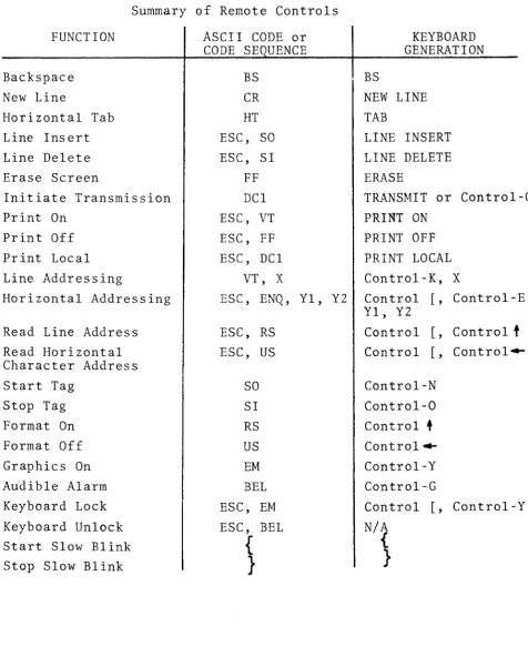
Summary of Remote Controls FUNCTION
Backspace New Line
Horizontal Tab Line Insert Line Delete Erase Screen
Initiate Transmission Print On
Print Off Print Local Line Addressing
Horizontal Addressing Read Line Address Read Horizontal Character Address Start Tag
Stop Tag Format On Format Off Graphics On Audible Alarm Keyboard Lock Keyboard Unlock Start Slow Blink Stop Slow Blink
ASCII CODE or CODE SE UENCE
BS CR HT ESC, SO ESC, SI
FF DCl ESC, VT ESC, FF ESC, DCl
VT, X
ESC, ENQ, Yl, Y2 ESC, RS
ESC, US SO SI RS US EM BEL ESC, EM ESC, BEL
{
}
BS
KEYBOARD GENERATION
NEW LINE TAB
LINE INSERT LINE DELETE ERASE
TRANSMIT or Control-Q PRINT ON
PRINT OFF PRINT LOCAL Control-K, X
Control
I,
Control-E, Yl, Y2Control [, Control
t
Control [, Control~Control-N Control-O Control
+
Control--Control-Y Control-GControl [, Control-Y N/A
{
[image:31.615.86.563.70.672.2]~.
A@t;1I CODE CHART Fig.4·1
b7 0
0 0 0 1
~
B.
0 0 1 1 1 0 0 1 1 1 1bs 0 1 0 1 0 1 0 1
Its b4 bJ b2 bl ~
0 1
2
3
4
5 6 7I , , I ROW'
0 0 0 0 0
NUL
OLE
SP
0•
P
, p0 0 0 1 1
SOH
DC1
!1
A
Q
a q0 0
1
0 2STX
DC2
"
2B
R
b r 0 01 1
3
ETX
DC3
#3
C
S
c s 01
0 04
EOT
DC4
$4
0T
d t 01
01
5ENQ
NAK
%5
E
U
e u 01
1 0 6ACK
SYN
& 6F
V
f v0
1
11
7BEL
ETB
, 7G
W 9 w1 0 0 0 8
BS
CAN
( 8H
X
h x1
0 0 1 9HT
EM
) 9I
Y
i y1 0 1 0 10
LF
SUB
*
: J Z j z1 0 1 1 11
VT
ESC
+ ;K
[ k {1
1 0 0 12FF
FS
, <L
\I
I I1 1 0
1
13
CR
GS
-
=M
] m }1 1 1 0
14
SO
RS
.
>N
-
n '"5.0 Protected Data and FORMAT Control
When the terminal is in any mode, a Formatting feature allows the display of both fixed and variable data. This feature is used primarily to display forms on the screen, thus making data entry easier and faster for the operator and also assuring that all necessary data is entered.
The Format feature is either "on" or "off" and is controlled by means of the Record Separator (RS) code for FORMAT ON, and by the Unit Separator (US) code for FORMAT OFF.
5.1 Format Off
With the Format feature "off", data can be entered in all character locations. If the operator depresses Control-N
(START TAG), or the computer sends SO, all subsequently entered data will blink. To stop the entry of blinking data, the operator must depress Control-O (STOP TAG), or the computer must send SI. Therefore, by using these keys the operator can display a page with some data blinking and other data displayed normally. The blinking data between a START and STOP TAG is called a tagged field.
During transmission of a Page or Message, each tagged field is preceded by a Shift Out (SO) code and followed by a
Shift In (SI) code. 5.2 Format On
When the operator depresses Control-
t
or the computer sends RS, the terminal enters the Format On state and tagged fields change appearance from blinking to half intensity. In the Format On state tagged data is not accessible and is considered "protected". The cursor skips over all protected data preventing it from being addressed, written over, or transmitted.(a) Data Entry With The Format On
D~ta is entered normally. However, if a character is entered in the last character position of an unprotected field, the cursor automatically skips over the intervening protected field and stops at the next unprotected character location.
(b) Control Functions With The Format On
In ~Asfmilar fashion, control functions will not
dis~ protected data. For example, the ERASE
rema1n1ng unprotected data on the current line and places the cursor at the first unprotected location on the next line.
In the Format On state, TAB does not move the cursor between the normal fixed tab stops. Rather, it moves the cursor to the first location of the next unpro-tected field or the Home position.
(c) Data Transmission With The Format On
When transmission is initiated in the Page mode, the cursor proceeds to transmit all the variable data
in the normal character sequential manner. Within the transmitted character string, a Group Separator
(GS) code is inserted for each protected field that was encountered and skipped. At low transmission speeds, the cursor can be observed moving on the
page as transmission proceeds. It stops at the first unprotected character location on the page after
transmission.
When transmission is initiated in the Message mode, the cursor proceeds to transmit all variable data in the normal character sequential manner. The GS code is inserted as usual to indicate protected fields. The cursor proceeds to the first variable position of the next line and the transmission is stopped. Note that if the next line starts with a protected field, a GS code will be'sent as the first character of the next line when (or if) the line is sent.
In either Page or Message mode, the Look-Ahead feature suppresses the trailing blanks at the end of a line for optimum transmission efficiency. That is, only the first blank from a group of trailing blanks is transmitted. For example, assume that at the end of a line we have the fol-lowing sequence:
•.•.• D, SP, SP, SP (five protected characters) SP, E, F, G, SF, SP, SP, SP, SP
In Format On state, we will transm~t:
• • . .. D, SP J SP, SP, GS, SP, E, F J G', SP, CR J
LF (LF not sent in Message mode)
shown abov~, the commas between characters are for annotation only. They are not sent by the terminal. When a protected field terminates a line and subse-quent lines are fully protected, only the first line terminator sequence (CR, LF) is sent in that part of the data stream.
As an illustration, consider a case in which we have a group of four lines on the display page as follows:
Line I -.
. ...
A, SP, (Protected field)Line 2 -. (Fully Protected) Line 3 - (Fully Protected)
Line 4
-
(Protected field), B, C,...
Upon transmission, the terminal sends ~A, SP, GS, CR, LF, B, C.
As a second illustration, consider the case in which the end-of a line is protected and all lines from that point to the end of the page are completely protected. The resulting ASCII character string
is-GS, CR, LF, ETX.
5.3 Protected Data in Conversational Mode
In the Conversational Mode, tagged data fields are preceded by the SO character and terminated by the SI character. This is the same as operating in the Page or Message modes. However, the user must be
6.0 Graphics
The Graphics mode is enabled when the terminal receives the ASCII control code EM from the computer or the keyboard (EM
is generated at the keyboard as Control-Y.) In this mode "tagged" characters are treated as graphics characters and untagged characters are displayed as the usual alphanumeric characters. Thus, simultaneous presentation of graphic and alphanume,ric characters is poss ib Ie. The terminal leaves the graphics mode upon receiving either ASCII Control Co~e
as
or US. ("FORMAT ON" or "FORMAT OFF")Normally, the "tag" bit is the eighth bit that is appended to 7 bit alphanumeric characters to control protected format information. When the graphics mode is enabled (by use of code EM), the tag bit is used to control generation of gra-phics rather than controlling access protection or bli~k.
Graphic characters consist of small rectangles which are sharply defined since they are formed by actually blanking the video signal, rather than by generating dot patterns. Resolution for graphics generation is 160 horizontal elements x 72 vertical elements, covering the display page. ~O~12
6.1 Graphic Character Generation
A character position can be thought of as cont'aining any combination of up to six elements. The elements positions are numbered as follows:
1 2
3 4
5 6
Graphic tagged characters (selected from ASCII columns 2 - 7) are interpreted as follows:
Bit 1 = 1 means darken element I
Bit 2 = I means darken element 2
Bit 3 1:1 I means darken element 3
Bit 4 1:1 1 means darken element 4
Bit 5 1:1 1 means darken element 5
Bit 6 1:1 I means darken element 6
Bit 7 1:1 not used
b7 b 6 bS b4 b3 b 2 hI
T I 0 1 0 1 0 0
if
9 0 1 1 I 0 0 1
I
z
1 0 1 1 0 1 0m
K 1 0 0 1 0 1 I
m
Thus, graphic characters displayed on the same line can generate solid horizontal lines
Or, graphic characters displayed in the same column can generate solid vertical lines.
7.0 Slow Blink
This feature permits data to be displayed as blinking, regardless of whether that data is protected or not. Data protection and graphics are controlled by a "tag" bit in memory. Additional control is provided by means of writing two characters:
left hand bracket, { (Shift-[) right hand bracket,} (Shift-])
When a { is encountered, the characters to the right of that character blink at a slow rate (2 times per second) until either a } or the end of the line is encountered.
Normal alphanumeric characters between { and} blink twice per second.
Protected characters between { and} appear at half-intensity and blink at a rate of twice per second. Unprotected, tagged data, which would normally blink 4 times per second, blink at a rate of 2 times per second when within brackets.
Graphical data does not blink when enclosed between brackets.
This feature may be utilized for a wide variety of effects. Several examples are given below:
EXAMPLE 1
A data field such ABeD enclosed within brackets ... { ABeD}
blinks twice per second. (The blinking data is shown under-lined in these examples.)
EXAMPLE 2
The ON-OFF blink control is within a line and is, from left to right, { ... } . See example below .
. . . { ABeD} ... {{ EFG}
EXAMPLE 3
The end of a line acts just like} as a "stop slow blink" control .
• • • { XYZ (end of line)
Note: The use of { and} to cause blinking characters is independent of whether those two characters are tagged or not. That is, the { and} could be protected or unpro-tected if the terminal is in the FORMAT ON state. The scanning algori thm which looks for { and then a } (or end of line) to mean
"start slow blink" "stop slow blink"
8.0 Peripheral Interfaces (Table 8-1)
The primary function of the peripheral interfaces is to accept ADDS Printers. A user need only plug these devices into the terminal with cables supplied by ADDS and does not have to be concerned with details of the interface. However, the systems' designer can use these flexible interfaces as Itadditional ports" to the terminal.
The basic terminal comes with two peripheral interface ports: - A Parallel Port
Suitable for driving a printer or similar device which accepts bit-parallel TTL ASCII characters. The ADDS printer uses this interface.
- A Serial Port
Suitable for sending information to, or receiving data from ASCII-coded serial EIA devices such as teleprinters, incremental tape drives, and ASCII-coded instrumentation. The speed of transmission to and from the serial device is controlled by the communication interface baud rate switch. 8.1 Peripheral Data Flow
The flow of data to the peripheral ports comes from either the communication line or the terminal memory. The opera-tor can control this flow by depressing the PRINT ON,
PRINT OFF, or PRINT LOCAL keys on the keyboard. Remote control of this is possible through the use of three ASCII code sequences corresponding to the three keyboard keys.
(a) PRINT ON Operation
Depressing the PRINT ON key or remotely enabling the function by sending the ASCII sequence ESC, VT causes the following:
~he peripherals receive all data sent between the CRT terminal and the computer, when the terminal is set to HALF-DUPLEX. In this
manner the peripherals are used fOir "on-line" logging of the computer-terminal dialog.
,Note: When operating with the PRINT ON state enabled, the user must be sure that the peripherals connected to the Serial and Parallel ports can operate at the speed of the communications line.
To inhibit the flow of data to the peripheral interfaces, the operator must depress the PRINT OFF key or the
computer can send the ASCII sequence ESC,FF. (b) PRINT LOCAL Operation
Depressing the PRINT LOCAL key or the receipt of the ASCII sequence ESC, DCI, initiates a block transfer
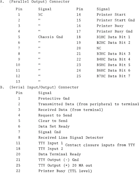
Table 8.1
PRINTER/CASSETTE INTERFACE PIN ASSIGNMENTS
A. (Parallel Output) Connector Pin 1 2 3 4 5 6 7 8 9 10 11 12 13 Signal NC " " "
Chassis Gnd " " " " " " " " Pin 14 15 16 17 18 19 20 21 22 23 24 25 B. (Serial Input/Output) Connector
Pin Signal
1 Protective Gnd
Signal
Printer Start Printer Start Gnd Printer Busy
Printer Busy Gnd BIHC Data Bit 1 B2HC Data Bit 2 NC
B3HC Data Bit 3
B4HC Data Bit 4 B5HC Data Bit 5
B6HC Data Bit 6
B7HC Data Bit 7
2 Transmitted Data (from peripheral to terminal)
3 Received Data (from terminal) 4 Request to Send
5 Clear to Send
6 Data Set Ready 7 Signal Gnd
Received Line Signal TTY Input 1 C t on ac t TTY Input 2
Data Terminal Ready TTY Output (-) Gnd
Detector
closure inputs from TTY
8
11
18
20
21
[image:43.615.97.546.129.695.2]9.0 Communications Interface
The terminal is provided with both an EIA RS232C interface and a 20 MA current loop interface. Those EIA signals which apply to this class of terminal (asynchronous data communica-tion) are assigned to pins in accordance with EIA Specifica-tion RS232C for interfacing data communicaSpecifica-tion equipment, with one exception as noted in Table 9.1. Both the standard EIA circuit name and the circuit name used in Euro~e (CCITT Specification V24) are shown in Table 9.1. Pins which are unassigned by RS232C for asynchronous data communication are used for the Current Loop interface and for additional chassis GND connections, which are useful for constructing data cables. 9.1 ErA Signal Definition and Description
All signals at this interface are not required for most applications. Signal descriptions are grouped from most commonly used to least frequently used.
(a) Protective Ground and Signal Ground (AA and AB)
These two signals
Pin 1 - AA Protective Ground
Pin 7 - AB Signal Ground
should be carried in a cable to a device such as a modem which is wired in accordance with RS232C.
In-ternally in the terminal these signals are tied to-gether at one point.
(b) Transmitted Data and Received Data (BA and BB)
The "primary channel" data lines
Pin 2 - BA Transmitted Data (from terminal) Pin 3 - BB Received Data (to terminal)
are the lines on which data goes to and from the ter-minal.
The interface conventions are as follows:
Data can be output on BA when Clear to Send (CB) is in the "On" state. A 250 millisecond "long space" is forced on this line when the operator's BREAK key is pressed.
electro-(c) Request'to Send and Clear to Send (CA and CB) These control lines
Pin 4 - CA Request to Send Pin 5 - CB Clear to Send
are normally used in either of two situations:
When operating on a Half-Duplex channel such as a "two-wire" 202 modem, or
Hardwired to a computer which senses CA to deter'-mine when the terminal wants to transmit and con-trols CB to permit the terminal to transmit only at the CPU's discretion.
The interface conventions are:
Signal CA is turned "On" when the terminal has data to transmit. CA goes "On" when the first character is typed and goes "Off" when
(1) An ETX is sent in the Page mode, or the (2) New Line function occurs in the Message
or Conversational modes.
Data will not be transmitted until CB is "On". If CB is "Off" the first character from the keyboard is buffered and then permitted to go out when CB goes to the "On" state.
CB is assumed "On" if left open (disconnected) at the interface.
(d) Received Line Signal Detector (CF)
If this signal, on Pin 8, goes to the "On" state the CARRIER indicator on the terminal is illuminated.
If CF is left open (disconnected) the CARRIER indicator does not illuminate.
(e) Secondary Request to Send and Secondary Received Line Signal Detector (SCA and SCF)
Pin 11 -SCA Secondary Request to Send
Pin 12 - SCF Secondary Received Line Signal Detector
SCA and SCF are used for circuit assurance and in-terrupt capability between the CPU and the terminal,
SCA is controlled by the terminal to inform the CPU of circuit assurance and may also be used to interrupt the CPU. SCA is held "On" when the terminal is receiving data, with the exception that if the operator presses his BREAK key a 200 millisecond "Off" condition occurs on SCA.
SCF is used by the computer to force the termi-nal from a transmit state to the receive state. If SCF goes to the "Off" state the terminal is forced to a receive state and cannot send data until SCF goes "On again.
Note: If SCF is open (not connected) it is assumed by the interface to be "On".
9.2 EIA Voltage Conventions
Signal CD on Pin 20 (DATTRY) is held at +13 Volts whenever power is on.
Signal Levels: (All data signals from the terminal are +l3V from a 680-0hm source impedence.)
For CA, CB, CF, SCF, SCA and CD "On"
=
+3V to +15V"Off"
=
-3V to -l5V For BA and BBMARK
=
-3V to -15V - Logical 1 SPACE=
+3V to +15V - Logical 0Note: Circuits CB and SCF are assumed to be true if no signal is applied, i.g., open input.
9.3 The Current Loop Interface
operation of the current loop. The two interfaces are mutually exclusive.
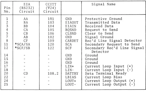
Table 9.1
980 Data Connector Pin Assignments
EIA CCITT Signal Name Pin (RS232) (V24)
No. 1 2 3 4 5 7 8 11 12 14 15 16 17 18 20 22 24 25
*
Circuit Circuit
AA 101 GND Protective Ground BA 103 EIAOUT Transmitted Data BB 104 EIAIN Received Data CA 105 RQSND Request to Send CB 106 CLSND Clear to Send AB 102 GND Signal Ground
CF 109 CARDET Rec'd Line Signal Detector *SCA/SA 120 SCA Secondary Request to Send *SCF/SB 122 SCF Secondary Rec'd Line Signal
Detector
-
- GND Ground-
-
GND Ground- - GND Ground
-
- LIN+ Current Loop Input (+)-
-
LIN- Current Loop Input (-)CD 108.2 DATTRY Data Terminal Ready
-
-
LBIAS Current Loop Bias-
-
LOUT+ Current Loop Output (+)-
-
LOUT- Current Loop Output (-)There is a discrepancy between RS-232C and standard assignments on Bell System 202 modem; i.e.,
202-name 202 Pin # R~232 name RS232 Pin #
SA 11 SCA 19
SB 12 SCF 12
[image:49.613.71.552.159.480.2]