AHA-1740A/1742A/1744
EISA-to-Fast SCSI Host Adapter
Technical Reference Manual
adaptee
AHA-17
40A/17 42A117 44
EISA-to-Fast SCSI Host Adapter
Copyright
© Copyright 1992 Adaptec, Inc. All rights reserved. No part of this publication may be reproduoed, stored in a re-trieval system, or transmitted in any fonn or by any means; electronic, mechanical, pbotooopying, recording or otherwise, without the prior written consent of Adapt.ec, Inc., 691 South Milpitas Blvd., Milpitas, CA 95035.
Trademarks
EISA is a registered trademark ofBCPR Services Inc.
Intel is a registered trademark, and 286, 386 are trademarks of Intel Corporation.
IBM, OS/2, PC AT, and Micro Channel are registered trademarks of International Business Machines Corporation.
MS-DOS, MS, Wmdows, Xenix, and Microsoft are registered trademarks of Microsoft Corporation.
Novell and NetWare are registered trademarks of Novell, Inc. QEMM is a trademark of Quarterdeck Office Systems.
sea
is a trademark of the Santa Cruz Operation.SYTOS and Sytos Plus are trademarks ofSytron Corporation.
QRAM, Move 'Em, and 386-Max are trademarks ofQualltas, Inc. UNIX is a registered trademark of AT&T Bell Laboratories.
Changes
The material in this manual is for infonnation only and is subject to change without notice. While reasonable ef-forts have been made in the preparation of this manual to assure its accuracy, Adaptec, Inc. assumes no liability resulting from errors or omissions in this manual, or from the use of the infonnation contained herein.
Adaptec reserves the right to make changes in the product design without reservation and without notification to
its users.
Additional infonnation may be obtained from:
adaptee
FCC Compliance Statement
NOTE: This equipment has been tested and found to comply with the limits for a Class B digital device, pursuant to Part 15 of the FCC rules. '!hese limits are designed to provide reasonable protection against harmful interfer-ence in residential installations. This equipment generates, uses, and can radiate radio frequen~ energy, and if not installed and used in acoordanoe with the instructions, may cause hannful interference to radio oommunica-tions. However, there is no guarantee that interference will not oo::ur in a particular installation.
If this equipment does cause interference to radio or television equipment reception, which can be determined by turning the equipment off and on, the user is encouraged to try to correct the interference by one or more of the
following measures:
•
•
Reorient or relocate the receiving antenna Move the equipment away from the receiver
•
•
Plug the equipment into an outlet on a circuit different from that to which the receiver is powered Ifnecessary, the user should consult the dealer or an experienced radio/television technician for ad-ditional suggestions
CAUTION: Only equipment certified to comply with Class B (computer input/output devices, terminals, printers,
etc.) should be attached to this equipment, and must have shielded interface cables.
Finally, any change or modifications to the equipment by the user not expressly approved by the grantee or manufacturer could void the user's authority to operate such equipment.
Table of Contents
Preface ... xi Conventions ... xii
Chapter One - Introduction
Document Scope ... 1-1 Purpose ... 1-1 AHA-1740A/1742A/1744 Product Features ... 1-2 EISA Features ... 1-2 SCSI Features ... 1-2 Board Features ... 1-3 Configuration Diskette and Installation Guide (ASW-C174) ... 1-4 Product Specifications ... 1-5 Extended Industry-Standard Architecture Interface ... 1-5 Standard EISA Bus Electronic and Physical Interface ... 1-5 SCSI Interface ... 1-6 Electrical Interface for AHA-1740A/1742A ... 1-6 Electrical Interface for AHA-1744 ... 1-7 Internal Connector ... 1-7 External Connector ... 1-8 Floppy Disk Interface ... 1-9 Standard Electronic and Physical interface ... 1-9 Connector ... 1-9 Radiation Immunity ... 1-9 Reference Documents ... ; ... 1-9
Chapter Two - Architecture
Table of Contents
ASW-CI74 Configuration Diskette ... , ... 2-12
Chapter Three - Installation
Unpacking and Inspection ... 3-1 Installation ... ' ... 3-1 System Configuration Background for Standard Mode ... 3-2 Preparation ... 3-2 Termination ... 3-3 SCSI Addressing (ID) ... 3-3 SCSI Parity ... 3-4 Hardware Installation ... 3-4 Checklist ... 3-7 Terminators ... 3-7 System Configuration ... : ... 3-7 MCS Configuration ... 3-9 Standard Mode SCSI Configuration ... 3-11 Enhanced Mode SCSI Configuration ... 3-12 Multiple Adapters Sharing Same SCSI Bus ... 3-14 Phoenix Configuration ... 3-15 Floppy Disk Configuration ... 3-15 ADL Utility ... 3-15 ADL Operation ... 3-16 List of Adapters ... 3-16 Main Menu ... 3-16 Download Firmware (AHA-1740/1744 Only) ... 3-17 Firmware Information (AHA-1740/1744/1740A/1742A) ... 3-18 Low-level Format ... 3-18
Chapter Four - Hardware Functional Description
Table of Contents
Digital Output Registers (Write 3F2) ... 4-23 Diskette Controller Registers (Read/write 3F4 and 3F5) ... 4-24 Digital Input Register (Read 3F7) ... 4-25 Diskette Control Register (Write 3F7) ... 4-25 Firmware Download (AHA-1740/1744 Only) ... 4-26 Hardware Configuration Requirements ... 4-27 SCSI Configuration ... 4-27 BIOS Driver Needs ... 4-28 SCSI Subsystem Configuration ... 4-28 Initialize SCSI Subsystem Command (Standard Mode) ... 4-28 Initialize SCSI Subsystem Command (Enhanced Mode) ... 4-28 Configuration Byte Description and Defaults ... 4-29
Chapter Five - Standard Mode Firmware Description
Table of Contents
Interrupt Initialization ... 5-32
Chapter Six - Enhanced Mode Firmware Description
Table of Contents
SCSI Bus Reset Handling ... 6-46 Reset Initiated by the Host ... 6-46 Reset Initiated by the Host Adapter ... 6-47 Reset Initiated by Another SCSI Device ... 6-47
Chapter Seven - Onboard BIOS Interface
Introduction ... 7-1 Operation with the Standard Interface ... 7-1 No Standard Hard Disks Installed ... 7-2 One Standard Hard Disk Installed ... 7-2
Two Standard Internal Hard Disks Installed ... 7-2 Enhanced Interface Operation ... 7-2 Hardware ... 7-2 Initialization ... 7-2 Boot Issues ... 7-4 Interrupt 13h Interface Functionality ... 7-5 Physical to Logical Block Address Translation ... 7-5 Virtual to Physical Buffer Address Translation ... 7-5 BIOS Command Return Codes ... 7-6 Hardware BIOS Commands ... 7-7 Int 15h Functionality ... 7-9 Differences Between Operating Modes ... 7-9 Multiple Adapter Support ... 7-10
Chapter Eight - Device Drivers
DOS Operation without Drivers ... 8-1 Standard Mode ... 8-1 Enhanced Mode ... 8-1 System Configuration ... 8-1 Low-Level Format ... 8-2 Installation and Initialization Under DOS ... 8-2 Managers ... 8-3 DOS Manager ... 8-4 Microsoft Windows 3.0 and Extended Memory Managers ... 8-5 OS/2 Manager ... 8-5 Novell NetWare Manager ... 8-6 U
nix/X.enix
Manager ... 8-6Chapter Nine - SCSI Features
Table ot Contents
SCSI Messages ... 9-3 Target Mode SCSI Description ... 9-3 Initiator Conformance Level Requirements ... 9-3 Synchronous Transfer Support ... : ... 9-4 SCSI Target Operation in Processor Target Mode ... 9-4 Incorrect Length Management for Target Mode Operation ... 9-9 Aborting Target Mode Commands ... 9-10
Chapter Ten - Problem Determination
Self Diagnostic Capability ... 10-1 Indicators ... ~ ... 10-2 Problems Detected During Operation ... 10-2 HA Status Error Indications and Corrective Actions ... 10-3 SCSI Error Indications and Corrective Actions ... 10-5 Problems Detected During Installation ... 10-6
Chapter Eleven - Glossary
Glossary of Terms ... 11-1
Appendix A - Memory Cycle Timing Diagram
AHA-1740N1742N1744 Timing Diagram ... A-I
Appendix B - Connector Pinout
Internal Connector Pin Assignments ... B-1 External Connector Pin Assignments ... B-3
Appendix C - Register Reference
System Register Reference ... C-l
[image:12.612.109.501.86.172.2]Preface
This Technical Reference Manual provides technical information for Adaptec's AHA-1740A/1742A/1744 EISA-to-Fast SCSI Host Adapters. It is prepared for cus-tomer technical personnel requiring detailed information on the operation of the board at a register and command protocol level. Documentation of board schematics, integrated circuits, microcode and BIOS routines is not provided.
Programmers writing device drivers for specific perpherals are strongly advised to use the Advanced SCSI Programming Interface (ASP!) specification appropriate to the operating system chosen. This will allow flexibility across all boards complying with ASPI Manager modules and prevent obsolescence. Please contact Adaptec Corporate Communications for copies of ASPI specifications. Software managers are documented and sold separately.
Conventions
The following typographic conventions are used throughout this Technical Reference Manual.
bold
Used for keystrokes ( .. press the Enter key .. ) and screen selection fields ( .. select
Backup Device and .. ).
Helvetica
Used for operator entry that must be typed exactly as shown .
( .. device=c:\cdrom'cdrom.tsc1 .. ) and for screen messages ( .. , Enter Password .. ).
Helvetica Italics
Used as a placeholder for text you must determine and type in ( .. enter nn for number .. ). Also used for program and file names in body text '(.: the autoexec.bat file .. ).
Italics ,;
Used for emphasis ( .. is only supported .. ) and document reference ( .. refer to Chapter Three, Installation .. ). .
ALL CAPITALS . '\
Chapter One
Introduction
Document Scope
This manual provides information on installation and defines the program interfaces of the AHA-1740N1742N1744 intelligent host adapters in EISA bus-based systems. Programming peripheral drivers directly to the hardware interface of the board is not recommended. The ASPI (Advanced SCSI Programming Interface) specifications pro-vide a simpler and more flexible interface which is protected against changes, up-grades and obsolescence of the boards.
Purpose
The Adaptec AHA-1740N1742N1744 provides a powerful multitasking interface be-tween the Extended Industry Standard Architecture (EISA) bus and the Small Com-puter System Interface (SCSD bus.
The AHA-1740N1742N1744 is a high-performance intelligent host adapter which supports a maximum asynchronous SCSI rate of2.0 MBytes/second and a synchro-nous transfer rate of 10.0 MBytes/second. It supports multithreaded I/O operations, allowing simultaneous operations on mUltiple targets/LUNs. Disconnect/Reconnect support maximizes bus utilization for multiple target systems. Target mode opera-tion allows the AHA-1740N1742N1744 to receive informaopera-tion from other host adapt-ers. Scatter/Gather allows high performance even in systems with fragmented memory butTers.
The AHA-1740N1742N1744 provides a solution for system applications requiring very high performance, configuration flexibility, multithreaded I/O capability, and system redundancy. The Adaptec BIOS also allows the AHA-1740N1742N1744 to be used in place of a standard hard disk controller.
The AHA-1740A/1742A host adapter provides high-performance host adapter cir-cuitry connected to the more common single-ended SCSI bus. The SCSI specification recommended maximum cable length for 5 MBytes/second synchronous data transfer is 6 Meters, or about 20 feet.
adaptee AHA-1740A/1742A/1744
AHA-174DA/1742A/1744 Product Features
EISA Features
The AHA-1740A/1742A/1744 is a full-performance EISA board offering the highest performance available across the bus. It takes advantage of first-party DMA opera-tions, also known as bus mastering, which allow data transfers to proceed at high data rates without system processor intervention. The main EISA functions which come standard on the board include:
• Auto Configuration Support
•
•
•
•
•
•
•
•
High-performance Bus Master transfers with burst cycles which provide a
data rate of 33 MBytes/second qt"
32-bit data path
32-bit address space
Even or odd starting address and byte count handling
1K FIFO for efficient data transfer
Interrupts enabled/disabled through 1/0 port write
Interrupts configurable for either edge or level trigger
Dual Control Interface, AHA-1540 family-compatible (Standard Mode) or ElSA-SCB compatible (Enhanced Mode)
SCSI Features
Adaptec has long been a supplier of leading edge SCSI products and the AHA-1740A/1742A/1744 is no exception. The board uses industry-standard protocol ICs which fully comply with the 1990 ANSI SCSI specification, including:
•
•
•
•
•
Maximum synchronous SCSI transfer rate of 10.0 MBytes/second (Fast SCSI)
Asynchronous and synchronous peripherals supported simultaneously
Disable synchronous negotiation independently on each target as a configura-tionoption
Disable disconnection independently on each target as a configuration option
EISA-to-Fast SCSI Host Adapter IntroducHon
•
•
•
•
•
Internal and external SCSI connectors
Initiator and target modes of operation fully supported
Differential SCSI (AHA-1744 only)
SCSI-1 and SCSI-2 compatible
Tagged queuing
Board Features
In addition to extensive functions on the two main interfaces of the board, the intelli-gence built into the board microcode and BIOS software allows a number of addi-tional functions to be offered, including:
•
Scatter/Gather operation•
Boot from any target (set as configuration option)•
Compatible with existing AHA-1540 family driver software (ASW-1400 series managers)•
True multithreaded operation supporting up to 255 tasks simultaneously•
Programmable mailbox architecture•
Bootable BIOS for standard hard disk emulation•
Floppy Diskette Controller (AHA-1742A only)While all versions of the board fully support all of the above features, they are distin-guished by:
•
AHA-1740A Fast SCSI-to-EISA Host Adapter• AHA-1742A Fast SCSI-to-EISA Host Adapter with floppy diskette controller
• AHA-1744 Fast differential SCSI-to-EISA Host Adapter
The AHA-1740A/1742A/1744 microcode is available in two separate versions which
c0-exist simultaneously in the onboard PROM, but must be configured into one of the two available modes:
• Standard Mode
• Enhanced Mode
adaptee
AHA-1740A/1742A/1744mode dictates the software manager revision which can support the board, but has no effect on the SCSI or host bus hardware connections.
Standard Mode allows software drivers written for the AHA-1540 or AHA-1640 fami-lies to run unaltered on the AHA-1740 family. There is no performance penalty for this on the EISA bus. The AHA-1740A/1742A/1744 still performs 32-bit transfers at speeds up to 33 MBytes/second.
Enhanced Mode allows the board to take advantage of a number of features which were not available on earlier host adapters. These include:
• Fast SCSI data transfer
• 32-bit addressing capability
• Ability to access all EISA board registers
•
Single fast mailbox handling• Tagged queuing (SCSI)
• Fully configurable SCSI bUs options for each SCSI target ID
Configuration Diskette and Installation Guide (ASW-C174)
As with other EISA boards, the AHA-1740A/1742A/1744 is configured by the EISA Configuration Utility (ECUrthat came with your EISA computer. The ASW-C174 diskette contains the configuration and overlay files required by the ECU for the AHA-1740A/1742A/1744. In addition, the ASW-C174 contains a utility for checking the version of microcode in your AHA-1740A/1742A/1744 and for low-level formatting of hard disks.
Note
The AHA-1740/1744 stores microcode in an E2PROM. You can download microcode
EISA-to-Fast SCSI Host Adapter Introduction
Product Specifications
Physical Dimensions
Length 13-3/8 inches Width 5/8 inch Height 5 inches Standard. ElSA-compatible form factor. Power Requirements
+5.0 +1-0.25 Volts at 2.9 Amps maximum. Environmental Requirements
Temperature 0-55° C (operating or storage) Reliability Information
Mean Time Between Failures: 100,000 hours
(calculated per Mil Handbook 217E, ground benign, 40° C) Mean Time Between Failures: (calculated)
1740A 61,466 hours 1742A 60,589 hours 1744 54,856 hours Mean Time to Repair: 30 minutes
Extended Industry-Standard Architecture Interface
Standard EISA Bus Electronic and Physical Interface
Driver Output Signals
VOL
o
volts minimumI
0.4 volts maximumIOL 24mA
VOH 2.4 volts minimum
I
5.25 volts maximumIOH 8mA
Receiver Input Signals
VIL 0.8 volts maximum
J
VIH 2.0 volts minimumadaptee
AHA-1740A/1742A/1744SCSI Interface
Eleetrieallnterfaee for AHA-1740A/1742A
As specified by ANSI X3.131-1986 for single-ended operation.
Output Signals
All signals use open collector or three-state drivers. Each signal driven by a SCSI de-vice has the following output characteristics when measured at the SCSI dede-vice's connector:
Signal Definition Characteristics
VOL Low-level output voltage 0.0 to 0.5 volts DC at 48 rnA sinking (signal assertion)
VOH High-level output voltage 2.5 to 5.25 volts DC (signal negation)
Input Signals
SCSI inputs meet the following electrical characteristics on each signal (including both receivers and passive drivers):
Signal Definition Characteristics
VIL Low-level input voltage 0.0 to 0.8 volts DC (signal true)
VIH High-level input voltage 2.0 to 5.25 volts DC (signal false) IIL Low-level input current -0.4 to 0.0 mA at VI
=
0.5 volts DC lIH High-level input current 0.0 to 0.1 rnA at VI=
2.7 volts DC Minimum input hysteresis=
0.2 volts DC.EISA-to-Fast SCSI Host Adapter Introducflon
Electrical Interface for AHA-1744
As specified by ANSI X359.2/86-109 Rev. 10h for differential alternatives.
Output Signals
Each signal driven has the following output characteristics when measured at the SCSI device's connector:
Signal Definition Characteristics
VOL Low-level output voltage 1. 7 volts DC maximum at IOL (low-level output current)
=
55 mA)VOH High-level output voltage 2.7 volts DC minimum at IOH (high-level output current)
=
-55 mA)Von Differential output voltage 1.0 volts DC minimum with with common-mode voltage ranges from -7 to + 12 volts DC VOL and VOH are measured between the output terminal and the SCSI device's logic ground reference.
Input Signals
SCSI inputs meet the following electrical characteristics on each signal (including both receivers and passive drivers):
Signal Def"mition Characteristics II Input current on either input +/- 2.0 mA maximum Maximum input capacitance
=
25 pF.The II requirement is met with the input voltage varying between -7 and +12 volts DC, with power on or off, and with the hysteresis equaling 35 millivolts, minimum.
Internal Connector
Unshrouded 50-pin header, compatible with unshielded alternative 1 connector as specified in ANSI X3.131-1986 (Figure 4-1).
For connector pin out and drawing of the connector, see Appendix B.
Partial list of compatible connector plugs (for reference only):
Manufacturer Model ParlNumber
3-M N.A. 3425-6000
T&BAnsley N.A. 609-5000M
noise-adoptee
AHA-1740A/1742A/1744External Connector
Shielded 50-pin high density (Alternative 1) connector as specified in proposed ANSI standard X3T9.2/86-109 Revision 10h, Section 4, Figure 5.
For connector pin out, see Appendix B.
Partial list of compatible connector plugs or cable assemblies (for reference only):
Manufacturer Model Part Number
AMP Connector 749111-4
Back Shell 749193-1
Fujitsu Connector FCN-237R050-G/F Back Shell FCN-230C050-D/E or -C/E
Honda Connector PCS-XE50MA
Back Shell PCS-E50LA
Cable for external SCSI connector should be good quality 100% shielded round cable with 25 twisted pairs. Each pair should have a characteristic impedance (Zo) between 90 ohms and 135 ohms. Wire gauge may be 26 or 28 AWG. All pairs should have the same impedance and should have the same delay per length of cable. Cables meeting these requirements will normally operate correctly in any SCSI configuration and should normally meet all FCC requirements.
For best results, the SCSI committee recommends that SCSI connectors should not be placed less than one foot apart on internal (ribbon) cable or on external cable when using Fast SCSI 10 Mbytes/second data transfers.
Cable material which meets this specification is available from a number of vendors, including:
Manufacturer Part Number Phone
C&T 16035
Madison 4099 (508) 752-7320
Complete cable asSemblies are available from a number of manufacturers. Among them are:
Manufacturer Phone
Amphenol Interconnect Products (607) 786-4370
Lynn Products Inc. (800) 634-5093 Quitec Interconnect Systems (408) 272-8000
EISA-to-Fast SCSI Host Adapter IntroducHon
Floppy Disk Interface
Standard Electronic and Physical interface
Driver Output Signals
VOL
o
volts minimum 0.5 volts maximum VOH Open collector 5.25 volts maximumIOL 60mA
IOH O.lmA
Receiver Input Signals
VT- 1.0 volts maximum
VT+ 1.4 volts minimum
Tied. to +5 volt supply through 150 ohm resistors. Schmidt Trigger with 0.8-volt hysteresis
Connector
Unshrouded 34-pin header. Partial list of compatible connector plugs (for reference only):
Manufacturer Model ParlNwnber
3-M N.A. 3414-6000
T&BAnsley N.A. 609-3400M
The cable for the floppy connector should be good quality 34 conductor flat cable with 28 gauge conductors. Addressing of the second drive may be generated by twisting connector signals 10 through 16 or by changing jumpers in the floppy disk drives.
Radiation Immunity
Meets radiation limits specified for a Class B computing device in accordance with the specifications in Subpart J of Part 15 of FCC Rules. See FCC Compliance notes and recommendations in preface of this document.
Reference Documents
•
EISA Specification, v3.11 from BCPR Services•
Intel 82355 (BMIC) functional data sheet Revision 2.5 or laterAmeri-adoptee
o
AHA-1740A/1742A/1744
• Adaptec AHA-1740A/1742A/AHA-1744 Host Adapter Installation Guide Us-ing the ASW-C174
Chapter Two
Architecture
Hardware
The hardware of the AHA-17 40A/17 42A/17 44 products is based on the latest VLSI technology for maximum performance in a minimum of board space. Where commer-cial products with sufficient performance and functionality were not available, Adap-tec has developed custom circuits using its long experience in high-performance silicon design for peripheral control applications. These parts are assembled on a mul-tilayer printed circuit board in Adaptec's volume manufacturing plant and subjected to a number of functional and mechanical inspections and tests.
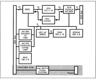
The general architecture of the board is shown in Figure 2-1.
BMIC
BIOS 16K x 8
8
FIFO 512 x 16
FIFO Control
HPC Jl.P 20MHz
16
16
RAM
32K x 16 SCSI Protocol AIC-6251
EPROM
[image:25.612.144.547.336.667.2]32K x 8
adoptee
AHA-1740A/1742A/1744Bus Master DMA
The AHA-1740N1742N1744 controls the host EISA bus as a master and transfers data directly to and from main system memory. This implementation is known as Bus Master DMA. Bus Master DMA greatly reduces the host software overhead be-cause the host CPU is no longer required to maintain the DMA channel's address pointers and word counts. Bus Master DMA also reduces the number of interrupts generated per I/O command. The Intel BMIC includes the functions of the DMA controller.
Adaptec's implementation of Bus Master DMA can achieve a 33 MByte/second burst data rate. This speed is especially valuable in multitasking systems where the tasks execute on a time shared basis. Appendix A, Memory Cycle Timing Diagram shows a diagram of the timing required to achieve the DMA rates that are supported by the AHA-1740N1742N1744.
The host adapter uses burst cycles on the EISA bus if the memory supports the fer by asserting SLBURST*.lfnot, the host adapter will use 32-bit wide data trans-fers with the normal 2 cycle timing. The adapter relies on system translation logic when reading or writing 16-bit expansion board memory in nonburst mode.
The AHA-1740N1742N1744 DMA hardware will handle both byte and odd-memory address data transfers with no performance degradation. The adapter has the ability to align bytes when the starting address is not a multiple of four or the byte count is an odd value. It will transfer 1, 2, or 3, bytes at the beginning or end of the transfer so that 32-bit burst cycles may be used.
The adapter will also be an 8-bit I/O slave with registers for use during setup and op-eration. Two modes of operation are defined which are mutually exclusive. The two modes are the AHA-1540 Standard Mode and the AHA-1740 Enhanced Mode. The current AHA-1540 ISA register set is implemented for software compatibility. The I/O address is selected by programming a configuration register. AHA-1740 En-hanced Mode is implemented to give extended addressing ability as well as addi-tional SCSI-2 features not available in Standard Mode. Several configuration registers are implemented in EISA I/O space to allow autoconfiguration.
The user may program the adapter to use interrupts 9, 10, 11, 12, 14, and 15. The in-terrupt may also be programmed to a high or low level. When the high level is used, the board will be compatible with the ISA implementation, and current drivers. When the low level is used, the interrupt may also be shared and EISA drivers may be written to use multiple boards on the same interrupt.
SCSI Interface and Protocol Chip (AIC-6251)
EISA-to-Fast SCSI Host Adapter Architecture
synchronous and asynchronous peripherals can be freely mixed on a cable connected to the AHA-1740A/1742A/1744.
In addition, the host adapter has the ability to select particular targets during con-figuration to initiate synchronous negotiation, enable parity checking, send start-up, and allow disconnection. The current limiting fuse on other host adapters has been re-placed with a thermistor to allow nondestructive current limiting of terminator power supplied to the SCSI cable.
The AHA-1740A/1742A/1744 utilizes the Adaptec AIC-625l Fast SCSI protocol chip to maximize the SCSI bus utilization. The AIC-625l is an Adaptec VLSI development of the popular AIC-6250 device which allows the AHA-1740A/1742A/1744 to achieve greater than 2.0 MBytes/second asynchronous SCSI data transfer rates, and up to 10 MBytes/second synchronous data transfer rates. The AIC-625l will also enable the AHA-1740A/1742A/1744 to operate simultaneously as both an initiator and as a proc-essor target device.
Through a 16-bit interface internal to the board, the AIC-625l reduces bus busy time during data transfer by allowing a bursting data across the EISA bus at up to 33 MBytes/second. The AIC-625l has separate data buses for the local microprocessor and for the system data bus. This further increases the performance of the AHA-l740A/1742A/1744 by reducing the overhead associated with SCSI commands.
8- and 16-Blt Memory and Odd Byte Data Transfers
The AHA-1740A/1742A/1744 will automatically shift to 8- or IS-bit data transfers as indicated by the control lines on the EISA bus. Bus master data transfers into 8- or l6-bit wide memory are fully supported as are full 32-bit wide data transfers.
During normal DMA operations, nearly all transfers to and from memory are 32-bit transfers. At the very end, or the very beginning of an odd address boundary, an 8-bit, l6-8-bit, or 24-bit transfer may occur.
Bus Auxiliary Interface Chip (AIC-565)
This highly integrated ASIC (Application Specific Integrated Circuit) device devel-oped by Adaptec is also used with the AHA-1540B host adapter family. It provides the Standard Mode programming interface and implements the following main func-tional blocks:
•
Bus control interface for Standard Mode•
Host adapter microprocessor interface•
BIOS decode logicac-adaptec AHA-1740A/1742A/1744
EISA Configuration Chip (AIC-575)
The host adapter provides a number of options which may be programmed at configu-ration time. They are summarized below:
• AHA-1540 base port address
•
Bus on time after preempt•
Interrupt definition and selection•
Synchronous negotiation enable/disable per target•
Disconnection enable/disable per target•
Boot drive identification for DOS•
BIOS enable, location, and optionsThe following versions of the ASW-1400 family of software managers support these features:
• ASW-1410, v3.0 and later
• ASW-1420, v1.3 and later
• ASW-1440, v3.0 and later
• ASW-1450, vl.O and later
BMIC Bus Interface Chip (82355)
This highly integrated ASIC device from Intel controls and interfaces to the EISA bus. It implements the following main functional blocks:
• 32-bit bus interface
• Adapter FIFO interface
•
EISA bus protocol logicFloppy Disk Controller (AHA-1742A Only)
EISA-to-Fast SCSI Host Adapter Architecture
systems with a large amount of bus latency, typically found in performance EISA systems.
Standard Mode Firmware
The AHA-1740A/1742A/1744 support multithreaded SCSI initiator operation through a simple mailbox protocol. The firmware accepts as many Command Control Blocks (CCBs) as required and executes them from its local RAM. The firmware controls all of the SCSI activity that a task may require, including:
•
Arbitration•
Selection•
Disconnection•
Reconnection•
Command completionU sing the same mailbox protocol, the AHA-17 40A/17 42A/17 44 can operate as a proc-essor-type device serving as a multitasking target to other initiators. This feature al-lows high bandwidth communication between multiple hosts.
In addition, the AHA-1740A/1742A/1744 firmware cooperates with the BIOS in-stalled on the host adapter to emulate the standard DOS BIOS calls. This allows boot-ing operations and the execution of standard DOS operations from attached SCSI disks, allowing the SCSI subsystem to completely replace the usual internal disk functions.
A multiuser, multitasking operating system issues a large number of I/O tasks in a rapid sequence. The architecture of the AHA-1740A/1742A/1744 makes management of this activity very easy and straightforward for the operating system and its associ-ated I/O drivers. This section briefly explains the interaction betWeen the system and the AHA-1740A/1742A/1744 required to accomplish an I/O task in standard mode.
Mailboxes
adaptec
AHA-1740A/1742A/1744A typical mailbox structure is:
BaseAdr +0 +4 +8 +12 +16 +20 +24 +28 CMD CMD 00 CMD 00 Status 00 00
CCB 4 Pointer
CCB 2 Pointer
Free Entry
CCB 3 Pointer
Free Entry
CCB 1 Pointer
Free Entry Free Entry MBOO MB01 MB02 MB03 MBIO MBI1 MBI2 MBI3
In this example there are four MBOs and four MBIs. The first byte of each MBO con-tains the MBO Command byte. The remaining three bytes point to a Command Con-trol Block (CCB). The CCB provides all the rest of the information needed to
complete a task. An MBO is available to accept a new entry if the first byte is zero.
The first byte of each MBI contains the status of a completed task. The remaining three bytes point to the CCB of the completed task. An MBI is free if the Status byte is zero. Mailboxes may point to CCBs controlling initiator tasks, controlling target tasks, or controlling error recovery tasks.
Command Control Block
A Command Control Block provides the information required to control a SCSI mand sequence. The block contains pointers to the data area to be used by the com-mand. It contains areas for presenting status of both the host adapter and the addressed SCSI device. In addition, it contains the SCSI Command Descriptor Block defining the action to be taken by the addressed SCSI device. An error information buffer area is also provided.
EISA·to·Fast SCSI Host Adapter
A typical CCB is shown below:
Byte 0
+1
+2
+3
+4
+7
+10
+13
+14
+15
+16
+17
+18
18+m
Tarnnit
Command Descriptor Block
I
Architecture
Command Control Block Opcode
Data Out
I
Data InI
LUNSCSI Command Length
=
m Returned Sense Info Length=
nData Length (MSB, MID, LSB)
Data Pointer (MSB, MID, LSB)
Link Pointer (MSB, MID, LSB)
Command Link 10
Host status
Target Status
Reserved
Reserved
SCSI Command Bytes (m Bytes)
Allocated for Sense Data (n Bytes)
The Command Descriptor Block (CDB), a part of the Command Control Block, is a standard format command packet that is transmitted to the addressed SCSI device. It contains all the command information required by the SCSI device to perform the desired operation. The Command Descriptor Block contains the command Operation Code followed by a Logical Unit Number (LUN), command parameters if required, and a control byte. A typical Group 0 6-byte CDB is shown below:
Bit 7
I
6I
5I
4I
3I
2I
1I
0Byte 0 Operation Code
1 LUN
I
Logical Block Address (MSB)2 Logical Block Address
3 Logical Block Address (LSB)
4 Transfer Length
adoptee
AHA-1740A/1742A/1744Please refer to the SCSI specification ANSI X3.131, the Common Command Set (CCS) revision 4B, and the SCSI-2 draft for additional information on Command De-scriptor Blocks.
Principles of Operation
At power-up, the host must inform the host adapter of the location and number of mailboxes. To start a task, the host builds a CCB and stores its memOIY address into a free mailbox. A nonzero Mailbox Out command byte is then written to indicate that the mailbox entry is full and valid. The host then writes to an I/O port (see Chapter Four, Hardware Furwtional Description) to indicate that the host adapter should scan the MBO area. When a full MBO is found, the host adapter copies the mailbox's CCB pointer into its internal RAM and clears the mailbox entry by writing a zero to the MBO command byte. This frees the MBO so that it can be used to start another task.
After completing a task, the host adapter scans the MBI area for a free mailbox. When one is found, it is updated with the task's completion status and CCB pointer. The CCB pointer identifies the completed task. An MBI stored interrupt is generated to notifY the host that a task has been completed. The host scans the MBI area searching for a nonzero Status byte. When one is located, the host obtains the CCB pointer and frees the MBI by writing a zero into the Status byte. The host then exam-ines the contents of the CCB to determine that the command was successfully com-pleted. The freed MBI can now be used to indicate the completion of another task. The host adapter fills the MBlarea and scans the MBO area in a round-robin fash-ion. If the host saves the position of the last active MBI entry, it can determine the MBI of a new entry immediately without searching, since a new entry will be in the next MBI location.
The host adapter transmits a new MBO Available or MBI Full interrupt to the host whenever all non-mailbox interrupts have been cleared and serviced by the host. The host should analyze the interrupts and clear them as soon as possible so that the host adapter can post any new interrupts quickly. The host adapter will not wait until an interrupt can be transmitted to the host before processing an MBO entry or creating a new MBI entry. Thus, in processing a single MBI interrupt, the host may find sev-eral MBI entries waiting by the time the interrupt processing is finished. Similarly, a later MBI interrupt for the last of the later MBI entries may find nothing to service because the MBI entry was examined and processed as a result of the first MBI Full interrupt. If the interrupts are reset quickly by the host, the probability of an inter-rupt occurring when no MBI entry is available is much lower, providing an important
~rformance improvement. If the MBI entries are emptied by the host in a
round-robin order, the scan for the next full entry is very simple, since it is always the next MBI entry in the mailbox area.
Task Queuing
targets/Logi-EISA-to-Fast SCSI Host Adapter Architecture
The host adapter dequeues on a first in, first out (FIFO) basis for each targetJLUN combination. However, due to the optimization algorithm used by the host adapter, a task may sometimes be started earlier in spite of its late entrance in the queue on multiple target/LUN systems. Task queuing should not be used where changes in the order of command execution may cause data integrity failures.
Enhanced Mode Firmware
The Enhanced Mode is an interface architecture which allows the
AHA-1740A/1742A/1744 to take full advantage of the EISA bus facilities. It utilizes a dis-tinct hardware interface control logic, implemented in the AIC-575 device. This permits features such as full 32-bit addressing and the entire EISA register set to be used. This mode is not compatible with older versions of the ASW-1400 series of soft-ware managers.
The following levels of manager revision are capable of operating with the AHA-1740A/1742A/1744 in Enhanced mode:
• ASW-1410 v3.0 and later (ASPI OOS Manager)
• ASW-1420 v1.3 and later (LADDR SCSI Support for OS/2®)
• ASW-1440 v3.0 and later (ASPI Manager for Novell NetWare®)
• ASW-1450 vl.O and later (SCSI Manager for SCO UN:oc® and Open Desktop)
In order to use the Enhanced Mode, the AHA-1740A/1742A/1744 must be correctly re-configured. Use the EISA Configuration Utility (EISA) that came with your EISA sys-tem and the EISA configuration files on the ASW-C174 diskette provided with the AHA-17 40A/17 42A/17 44. The AHA-17 40A/17 42A/17 44 are not capable of simultane-ous operation in Standard and Enhanced Modes.
adaptee
AHA-1740AI1742A/l744The control block is a 48-byte structure created and maintained in shared memory by software in the system unit. It is used to convey requests to the host adapter.
F E 0 C B A 9 8 7 6 5 4 3
Command Word
Flag Word 1
Flag Word 2
Data or Scatter/Gather List Pointer
0$1 or Scatter/Gather List Length
Status Block Pointer
Chain Address
Sense Information Pointer
COB Length Sense Length
Data Checksum
COB Byte 1 COB Byte 0
COB Byte 3 COB Byte 2
COB Byte 5 COB Byte 4
COB Byte 7 COB Byte 6
COB Byte 9 COB Byte 8
COB Byte 11 COB Byte 10
2 1 0
,
Byte Offset
00
02
04
06
08
OA
OC
OE
10 12
14 16
18
1A
1C 1E
20
22
24
26
28
2A
2C
2E
EISA-to-Fast SCSI Host Adapter Architecture
Onboard BIOS Operation
A host adapter BIOS is provided to emulate the standard hard disk BIOS and boot functions. With this BIOS, the host adapter can be used in lieu of a standard hard disk controller on any ISA-compatible system.
The BIOS is compatible with the standard hard disk BIOS. This allows DOS to ac-cess up to two hard disk devices on the SCSI bus without a driver. All normal I/O functions are supported including system booting. Single-threaded operation and mul-tithreaded operation do not operate simultaneously. Single-threaded operation can-not be requested until all multithreaded operations are completed. Similarly, all multithreaded operations must be complete before a single-threaded operation can be requested. For most multitasking operating systems, such as Xenix® and OS/2, sin-gle-threaded operation is normally used only for the early part of the boot operation, after which multithreaded drivers take over all control of the SCSI operations.
During system boot, the BIOS will scan for the availability of configuration informa-tion in the free-form data area of system RAM. If it finds the correct data format, it will use this data to configure both the board parameters and parameters associated with the peripherals on the SCSI bus. If data cannot be found or correctly recognized, the BIOS will configure the board to a default set of parameters. Refer to Chapter Three, Installation for details.
Power-Up Diagnostics
After power on, the host adapter initializes the firmware to 16-bit RAM for execution. After the firmware is running, the Extended ID is written to the registers. Several on-board diagnostics are then performed.
•
RAM is verified•
Write/Read registers are checked for proper operation•
The data path is checked for correct internal operationadoptee
AHA-1740A/1742A/1744Flash Code Possible Meanings of Flash Code
LED Remains On Host Adapter Control Processor inoperative, terminators missing or not powered, or card enable has not been asserted after reset.
1 Flash RAM test failed.
2 Flashes AIC-6251 SCSI protocol chip verification failed.
3 Flashes FIFO write/read data path test failed.
Continuous Flashes EEPROM has not been programmed.
ASW-C174 Configuration Diskette
The AHA-1740A/1742A/1744 is normally supplied with configuration software, prod-uct number ASW-C174. This includes 5.25-inch and 3.5-inch high-density diskettes and an installation guide. The two diskettes contain identical information. The func-tions of the files on the diskette may be supplied as part of the system utilities for the host system in which the AHA-17 40A/17 42A/17 44 is installed. The configuration disk-ette contains the following files:
•
•
•
•
•
•
•
•
•
ladpOOOO.cfg -Configuration file for the AHA-1740 (older version of the AHA-1740A)
ladp0400.cfg -Configuration file for the AHA-1744
ladp0001.cfg -AHA-1740A/1742A with floppy disabled
ladp0002.cfg -AHA-1742 with floppy enabled
ladp0100.cfg -AHA-1540B/1542B configuration file
ladpOOOO.ovl-Configuration overlay file for SCSI bus parameters
adl.exe -Microcode download utility, including low-level format utility
standard.hex -Current production release of Standard Mode microcode (AHA-1740/1744 only)
enhanced. hex -Current production: release of Enhanced Mode microcode (AHA-1740/1744 only)
EISA-to-Fast SCSI Host Adapter Architecture
The utility disk will also include copies of the microcode files for the AHA-1740/1744 to be downloaded by the download utility. These are normally not required, except in the case of microcode upgrade. The AHA-1740N1742A do not have downloadable microcode.
The configuration overlay file uses a freeform data area. This freeform data area is used to configure the SCSI bus and the specific structure within the freeform data area and is not specified by the EISA specification. Adaptec uses a data structure for each device (SCSI ID #n) consisting of two bytes, shown in the following table:
Byte2n+l Description Byte2n Description
bits 7-3 Reserved bit 7 Reserved
bits 2-0 Maximum sync Xfer rate bit 6 More than 1 LUN supported
000 10.0 MBytes/second bit 5 Parity check enable
001 6.67 MBytes/second bit 4 Send start command
010 5.0 MBytes/second bit 3 Sync negotiation enabled 011 4.0 MBytes/second bit 2 Disconnection enabled
100 3.33 MBytes/second bit 1 Ignore error if device not present
101-111 Reserved bit 0 Enable disk BIOS support
If your EISA system (and ECU) do not support the freeform data area, the AHA-1740N1742N1744 can still be used, but only at the default settings for the SCSI bus as shown in Chapter Three, Figure 3-5, Standard Mode SCSI Configuration Screen, and Figure 3-6, Enhanced Mode SCSI Configuration Screen.
Chapter Three
Installation
Unpacking and Inspection
The carrier is responsible for damage incurred during shipment. In case of damage. have the carrier note the damage on both the delivery receipt and the freight bill. then notifY your freight company representative so that the necessary insurance claims can be initiated.
After opening the shipping container. use the packing slip to verifY receipt of the indi-vidual items listed on the slip. Retain the shipping container and packing material for later use should return of the equipment to the factory be necessary.
CAUTION
The AHA-17 40A/17 42A/17 44 is carefully designed to resist the effects of static electricity. However. like all electronic equipment. it can be damaged or its life can be shortened by unusual static discharges. Please take the proper precautions when handling the board. Keep the board in its conductive wrapping until it is ready to be installed in your system. Be sure that the host computer and the per-sonnel handling the board are properly grounded while installing the board.
Installation
The following section details the installation procedure for the Adaptec
AHA-1740A/1742A/1744 EISA-to-SCSI host adapter. The installation of the board consists of unpacking the board. preparing the SCSI devices. installing the correct termina-tions. inserting the board into a full-length EISA-compatible connector. and connect-ing a SCSI cable from the onboard connector to a SCSI target. The system is then powered uP. the microcode downloaded and the board configured for operation.
The Adaptec AHA-1740A/1742A/1744 EISA-to-Fast SCSI host adapter has been de-signed to operate as shipped in standard EISA class computers. The board (or the sys-tem in which it is installed) is normally shipped with a configuration diskette which permits the board to be configured to the actual slot location in which it is installed. Unlike AT/ISA boards. but like Micro Channel boards. EISA boards do not normally require hardware jumpers.
electri-adaptee
AHA-1740A/1742A/1744WARNING
Connection of a single-ended board to a differential drive or vice versa may cause permanent electrical damage to one or both devices.
System Configuration Background for Standard Mode
The DOS operating system and standard BIOS supports two hard disk drives; drive C and drive D. If two standard hard disk drives are installed, they are the only hard disk drives accessible from the operating system. If one standard hard disk drive is installed, the AHA-1740A/1742A/1744 BIOS allows DOS to access the SCSI drive with the Target:LUN address of 0:0 as the second of the two supported drives (drive D). If no standard hard disk drives are installed, the AHA-1740A/1742A/1744 BIOS allows DOS to access the SCSI drive with the address of 0:0 as the first of two sup-ported drives (drive C) and the SCSI drive with the address of 1:0 as the second drive (drive D).
System booting is performed from the floppy drive if a floppy diskette is installed. If no floppy is installed, system booting is attempted from the drive chosen as drive C through the above process, whether the drive is a standard hard disk or a SCSI hard disk. The AHA-1740A/1742A/1744 BIOS fully supports the extended partitioning ca-pabilities of DOS for up to two drives. Adaptec supplies a range of products based on the Advanced SCSI Programming Interface (ASPI) architecture that allow the sup-port of more than two physical or logical devices under DOS. Many other operating systems, including SCO Xenix and Unix, also have this feature and will allow the ac-cess of any number of attached SCSI devices. Refer to Chapter Eight, Device Drivers for more details. Peripheral devices such as SCSI tape, DAT, CD-ROM and others re-quire device driver software to be installed.
Standard hard disk refers to the disks attached to the system by a standard ISA non-SCSI disk controller. These standard hard disks can be set to the installed or not in-stalled state by the Setup program that is supplied with each host computer. The Setup program allows the user to select the number of standard hard disks that are recognized by the system regardless of whether they are physically installed.
Preparation
Few preparatory steps need to be taken to install the host adapter in the host com-puter. The floppy controller enable/disable jumper on the AHA-1742A is the only con-figuration jumper. If you already have a floppy controller in your EISA system, disable the floppy controller on the AHA-1742A by removing the right-most jumper on jumper block J6.
ex-EISA-to-Fast SCSI Host Adapter InstanaHon
Each EISA system is shipped with a configuration utility to assign parameters such as port addresses and interrupt priorities to boards installed in the system. This must be used to identify and configure the board in your system. The details vary from vendor to vendor. Refer to the system documentation for details.
The Adaptec AHA-1740N1742N1744 32-bit EISA bus-to-SCSI bus host adapter has been designed to operate as shipped in the majority of EISA class computers. A board direct from the factory is normally shipped with the ASW-C174 Configuration
Utility. This utility permits parameters associated with the board and the SCSI bus to be set up through the system keyboard and CRT.
Termination
The SCSI bus must be terminated correctly to assure proper operation. The first and last physical SCSI devices on the SCSI cable must have terminators installed. All other SCSI devices must have terminators removed. The host adapter is shipped with terminators which are three Serial In-line Packages (SIPs) located near the 50-pin internal SCSI flat ribbon connector at locations RN3, RN4, and RN5. The inter-nal and exterinter-nal connectors connect to the same SCSI bus, so both interinter-nal and external cabling must be considered in determining where terminators are installed.
If only one cable (either internal or external) is connected to the host adapter, the ter-minators must remain installed in the host adapter. Terter-minators must also be in-stalled on the device at the farthest end of the cable from the host adapter. Terminators must be removed from all other attached SCSI devices.
If both an internal and external cable are connected to the host adapter, remove the terminators on the host adapter and install terminators on the devices at the farthest end of each cable. Terminators must be removed from all devices except the device at the end of each cable. The instruction manuals for each SCSI device will indicate how the terminators can be removed or replaced.
SCSI Addressing (10)
The SCSI target address for each SCSI device to be attached must be selected by set-ting the proper jumpers or switches on the device in Standard Mode. The SCSI device that is to be used as the boot disk must have a SCSI address of zero. In Enhanced Mode, you can boot to any SCSI ID. Refer to the section titled Enhanced Mode SCSI Configuration for further details.
SCSI Addresses 0 and 1 should be reserved for SCSI hard disk drives. Each installed peripheral must have a different SCSI address. The host adapter's default SCSI ID is 7. Duplicate SCSI addresses will cause errors that are extremely difficult to identify.
adaptee
AHA-1740A/1742A/1744SCSI Parity
Check all SCSI devices to ensure that they generate parity. If any SCSI device does not generate parity, then all SCSI devices should be set to disable parity checking. If all SCSI devices generate parity, it is recommended that parity checking be turned on for all devices. Please note that generating parity and checking parity are two separate functions. The AHA-1740N1742N1744 configuration overlay can be used to enable/disable parity checking for each SCSI ID.
Hardware Installation
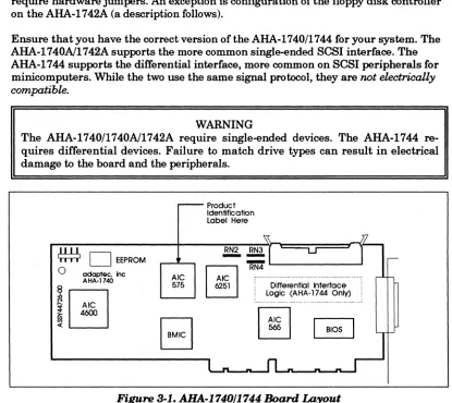
The Adaptec AHA-1740N1742N1744 EISA-to-Fast SCSI host adapter has been de-signed to operate as shipped in standard EISA class computers. The board (or the sys-tem in which it is installed) is normally shipped with a configuration disk which permits the board to be configured to the actual slot location in which it is installed. Unlike AT/ISA boards, but like Micro Channel boards, EISA boards do not normally require hardware jumpers. An exception is configuration of the floppy disk controller on the AHA-1742A (a description follows).
Ensure that you have the correct version of the AHA-1740/1744 for your system. The AHA-1740N1742A supports the more common single-ended SCSI interface. The AHA-1744 supports the differential interface, more common on SCSI peripherals for minicomputers. While the two use the same signal protocol, they are not electrically compatible.
WARNING
The AHA-1740/1740N1742A require single-ended devices. The AHA-1744 re-quires differential devices. Failure to match drive types can result in electrical damage to the board and the peripherals.
r - -Product Identification Label Here
~ Jl
~
o
EEPROM~
'::'1
- - U
1
,--0 adoptee. Inc RN4AHA-1740 Ale
@]
: ... ":~
575 6251 Differential Interface~
Logic (AHA-1744 Only)i
... ...B
I~I
~,J
«
l
[image:42.612.96.511.286.656.2]-EISA-to-Fast SCSI Host Adapter
o
I
MicrocodeI
o
I I I I 1"1"1 adaptee. incAHA-174011742A
~
!0
:a 575 1C«
Product Identfflcatlon Label Here
u
- - -
RN5 RN6 RN7B
I~~I
I
BIOSFloppy enable '--1'1-_'--..1 ... ...n._...n._n...a
jUlT1>8r
(normany present) Floppy secondary address jumper (normaHy absent)
Installation
Terminator Power Supply Jumper (normally present) _ _ _ - - . J
[image:43.612.135.541.95.325.2]Installed (default) = Host adapter will supply term power" Removed = Host adapter will not supply term power
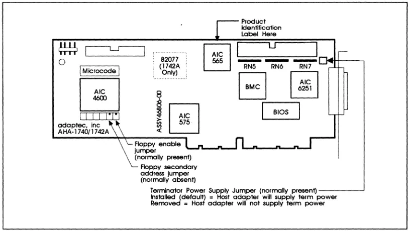
Figure 3-2. AHA.-1740A/1742A Board Layout
To perform hardware installation:
1. Turn ofT the power to the computer system.
2. Remove the cover of your EISA personal computer to expose the EISA bus slots on the motherboard.
3. Locate an unused EISA slot in your system which supports bus master operations. Refer to the host system documentation for details.
4. Remove the corresponding system expansion slot cover by turning the screw that secures it from the top, counterclockwise.
5. Examine the board to be installed. Ifit is anAHA-1742A, and your system already has a floppy disk controller, disable the floppy disk controller on the AHA-1742A by removing the rightmost jumper from jumper block J6 in the lower left corner of the board.
adaptee
AHA-1740A/1742AJ17447. Align the EISA bus connector on the bottom of the AHA-1740A/1 7 42A/17 44 to the open chassis slot with the slot cover removed. Ensure the external connector and bracket pass cleanly through the cutout in the rear wall.
8. Firmly plug the board into the slot. Use the screw from the corresponding expan-sion slot cover to secure the board bracket to the system frame.
9. If an internal SCSI peripheral is to be used, install a 50-pin SCSI ribbon cable to the host adapter. This cable must be oriented correctly; Pin 1 of the SCSI cable is designated by a red stripe. Multicolor 50-pin ribbon cables signify pin 1 with a brown color. Most cables and the corresponding sockets are keyed to ensure cor-rect orientation. Pin 1 on the host adapter 50-pin SCSI header is located on the lefthand side, farthest from the installation bracket. After locating pin 1 on the host adapter and on the SCSI cable, carefully insert the connector located at the end of the long end of the cable into the host adapter connector. On the AHA-1740A/1742A/1744, firmly seat the connector to the board such that the locking ears snap into place to hold the cable firmly. If it is ever necessary to remove the cable, gently push the two locking ears horizontally outwards along the axis of the board until the cable connector is pushed upward and free.
10. If an internal SCSI device is also being installed, it should be installed in the drive bays in accordance with the directions on the peripheral at this time. The proper power supply connection also must be made to the SCSI peripheral device.
11. The 50-pin SCSI ribbon cable can now be attached to each internal SCSI device. Refer to the device's installation instructions to ensure proper pin 1 orientation. Pin 1 orientation must be consistent throughout the system. Keep the ribbon ca-ble neatly dressed away from the ventilation slots in the computer system. Keep the ribbon cable dressed away from possible electrical noise sources or noise sen-sitive components, particularly large microprocessors, memory boards, switching power supplies, and analog data acquisition boards. If the internal configuration requires the cable to come near noise sensitive circuits, make sure that the cable crosses the boards at right angles and is near the noise sensitive circuits for the shortest'distance possible.
12. Carefully reinstall the cover of the computer.
13. If an external SCSI subsystem is being installed, it can now be cabled to the Exter-nal SCSI Connector projecting from the shielding bracket on the back of the AHA-1740A/1742A/1744 host adapter. The external connector on the
AHA-17 40A/17 42A/17 44 is a small form factor SCSI altemate-2 D shell connector that ensures correct pin 1 orientation on the host adapter. The correct shielded SCSI cable must be used for proper operation. Ensure that the external device drive types all correspond with the single-ended/differential marking on the bracket of the AHA-17 40A/17 42A/17 44 respectively.
EISA-to-Fast SCSI Host Adapter Installation
selected for external SCSI devices must not overlap with the addresses of the host adapter or any other SCSI devices attached internally.
Generally speaking, there can be no more than seven other SCSI devices attached, each with its own unique address and the total cable length must not exceed 20 feet for single-ended and 80 feet for differential.
Checklist
Before applying power to your system, the following items should be completed and checked:
•
•
•
•
•
•
Terminators
The 50-pin SCSI ribbon cable is connected to the host adapter with proper pin 1 orientation.
The host adapter is firmly seated in the host computer's adapter slot.
The correct SCSI addresses are selected on all attached SCSI devices. Ad-dress 0 is reserved for the boot hard disk and address 1 is used for a second hard disk.
The correct operating modes are selected on all attached SCSI devices.
Terminators are installed or removed on the drives and host adapter as required.
External SCSI devices are properly installed and cabled.
The SCSI bus must also be terminated correctly to ensure proper operation. The first and last physical SCSI devices on the SCSI cable must have terminators installed. All other SCSI devices must have terminators removed. The AHA-1740A/1742A/1744 host adapter is usually the first device on the SCSI Bus and has terminators in-stalled at the factory.
System Configuration
When it is being installed in an EISA system, the AHA-1740A/1742A/1744 requires an EISA system configuration file. This may be part of the system software or may be supplied on a separate diskette. If it is separate, installation is easier if the contents of the separate diskette are copied onto the main boatable system configuration disk.
To perform system configuration:
adoptee
AHA-1740A/1742A/17442. Ignore any error which indicates that an unknown board has been detected in the system. Selection of board configuration varies with the configuration utility sup-plied with the EISA system. There are two main types, supsup-plied by MCS and Phoenix. The type may be obscured by the screen banner used by the system ven-dor. Follow the procedure which is closest to your environment. In the case of the MCS configuration, type ct. For Phoenix configuration type ptlecu. Select board configuration and press the Enter key.
3. If the main configuration disk does not contain files for the
1740A/1742A/1744, copy the contents of the ASW-C174 diskette with the AHA-1740A/1742A/1744 configuration files to the boot floppy and run the
configuration program.
!adpOOOO.cfg for the AHA-1740 !adp0001.cfg for the AHA-1740A !adpOOO2.cfg for the AHA-1742A !adp0400.cfg for the AHA-1744
In addition, run adpOOOO.ovl for all boards. The configuration utility will usually allow selection among a number of options, including copying new con-figuration files .. Select this last option to install the appropriate files from the ASW-C174 floppy disk. To select the configuration utility on a system already running, insert the system configuration disk, select that drive and enter ct or ptlecu (see above).
EISA-to-Fast SCSI Host Adapter InstaliaHon
M CS Configuration
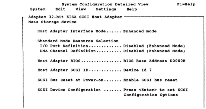
For configuration under MCS, select the slot in which the AHA-1740A/1742A/1744 is installed and press Enter. The screen will display the System Configuration De-tailed View. These settings should normally not be changed for Standard Mode opera-tion. Use the cursor arrows to make selections and the Enter key to enter the
selection. When installing multiple boards in Standard Mode, ensure that none share the same configuration parameters for port address. The configuration utility nor-mally automatically ensures that there is no conflict. SCSI ID can be the same pro-vided that the boards do not share the same SCSI bus. Normally, the host adapter is given address 7. A typical selection detailed view is shown in Figure 3-3. Use the ar-row keys to move around in a selection and the Enter or Return key to choose a highlighted selection. If a mouse is installed, it may also be used.
System Configuration Detail.d Vi.w Fl-H.lp System Edit Vi.w Settings H.lp
Adaptec 32-bit EISA SCSI Host Adapt.r - - - , Mas. Storage device
Hoat Adapt.r Interface Mode •••••• Enhanc.d mod.
Standard Mode Resource Selection
Ilo Port D.finition ••••••••••••• Disabled (Enhanced Mode) DMA Channel Definition •••••••••• Disabled (Enhanc.d Mod.)
Host Adapter BIOS •••••••••••••••• BIOS Baae Address DOOOOH
Host Adapter SCSI ID ••••••••••••• Device Id 7
SCSI Bus a.set at Pow.r-on ••••••• Enable SCSI bus res.t
SCSI Device Configuration ••••••• Preas <Enter> to aet SCSI Configuration Options
[image:47.612.193.534.291.471.2]Pres. (1'10) , select menu with arrow key •• Pull down selected menu with (Enter).
Figure 3-3. System Configuration Detailed VielD Screen
Normally, it is not necessary to alter any settings for configuration. Selection ofthe appropriate interrupt request will also select between Standard and Enhanced Mode. If-selecting Enhanced Mode, it is not necessary to alter the system resource selection, but if resources are left selected, they will be allocated, even if not used.
Select the AHA-1740A/1742A/1744 installation configuration as follows:
1. Select the host adapter interface mode. There are two available. Standard Mode allows software written for the 1540 or 1640 families to run the AHA-1740 Family. Enhanced Mode allows a higher-performance interface to be used.
adoptee
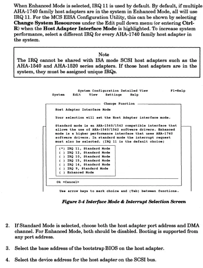
AHA-1740A/1742A/1744When Enhanced Mode is selected, IRQ 11 is used by default. By default, if multiple AHA-1740 family host adapters are in the system in Enhanced Mode, all will use IRQ 11. For the MCS EISA Configuration Utility, this can be shown by selecting
Change System Resources under the Edit pull down menu (or entering Ctrl-R) when the Host Adapter Interface Mode is highlighted. To increase system performance, select a different IRQ for every AHA-1740 family host adapter in the system.
Note
The IRQ cannot be shared with ISA mode SCSI host adapters such as the AHA-1540 and AHA-1520 series adapters. If those host adapters are in the system, they must be assigned unique IRQs.
System Configuration Detailed View System Bdit View Settings Help
Change Function
Host Adapter Interface Hade
Your selection will set the Bost Adapter interface mode.
Standard mode is an ARA-lS40/1S42 compatible interface that allows the use of ABA-lS40/lS42 software drivers. Enhanced mode is a higher performance interface that uses ARA-1740 software drivers. In .tandard mode the interrupt request must also be selected. (IRQ 11 is the default choice)
( *) IRQ 11, Standard Hode ( ) IRQ 12, Standard Hode ( ) IRQ 10, Standard Hode ( ) IRQ 15, Standard Hode ( ) IRQ 14, Standard Hode ( ) IRQ 9, Standard Hode ( ) Enhanced Hode
Ok <Cancel>
[image:48.612.91.508.75.625.2]Us. arrow keys to mark choice and (Tab) between functions.
Figure 8-4 Interface Mode & Interrupt Selection Screen
2. IfStandard Mode is selected, choose both the host adapter port address and DMA channel. For Enhanced Mode, both should be disabled. Booting is supported from any port address.
3. Select the base address of the bootstrap BIOS on the host adapter.
4. Select the device address for the host adapter on the SCSI bus.