University of Southern Queensland
FACULTY OF ENGINEERING AND SURVEYING
MOBILE MANOEUVRING
ROBOT
A dissertation submitted by
Mr. Matthew Free
in fulfilment of the requirements of
Courses ENG4111 and 4112 Research Project
towards the degree of
Bachelor of Engineering
(Mechatronics)
ABSTRACT
Robotic guidance is a large part of many research and design applications. It is being used more frequently in everyday lifestyles such as vacuum cleaners and lawn mowers, and is slowly being introduced into the automobile industry.
The need for this technology is growing evermore and different aspects and methods are being implemented, from various sensor types to camera machine vision. This dissertation is compiled to explore the use of one of these technologies implemented into a small unit.
University of Southern Queensland
FACULTY OF ENGINEERING AND SURVEYING
ENG4111 & ENG 4112 Research Project
Limitations of Use
The Council of the University of Southern Queensland, its Faculty of Engineering and Surveying, and the staff of the University of Southern Queensland, do not accept any responsibility for the truth, accuracy or completeness of material contained within or associated with this dissertation.
Persons using all or any part of this material do so at their own risk, and not at the risk of the Council of the University of Southern Queensland, its Faculty of Engineering and Surveying or the staff of the University of Southern Queensland.
This dissertation reports an educational exercise and has no purpose or validity beyond this exercise. The sole purpose of the course pair entitled “Research Project” is to contribute to the overall education within the students chosen degree program. This document, the associated hardware, software, drawings, and other material set out in the associated appendices should not be used for any other purpose: if they are so used, it is entirely at the risk of the user.
Prof R Smith
Dean
Certification
I certify that the ideas, designs and experimental work, results analysis and conclusions set out in this dissertation are entirely my own efforts, except where otherwise indicated and acknowledged.
I further certify that the work is original and has not been previously submitted for assessment in any other course or institution, except where specifically stated.
Matthew Phillip Free
Student Number: 0050009628
____________________________ Signature
ACKNOWLEDGEMENTS
This research was carried out under the principal supervision of Mark Phythian. Many thanks are due for his expertise and advice in the area surrounding the Mobile Manoeuvring Robot
Assistance was also obtained from Mr. Terry Byrnes. Many thanks also to his expertise and advice.
The University of Southern Queensland supplied vital components for the construction of the Mobile Manoeuvring Robot. Many thanks for the use of these components.
TABLE OF CONTENTS
Contents Page
ABSTRACT i
DISCLAIMER PAGE ii
CANDIDATES CERTIFICATION iii
ACKNOWLEDGEMENTS iv
LIST OF FIGURES viii
LIST OF TABLES ix
LIST OF APPENDICES x
NOMENCLATURE xi
1. CHAPTER 1 – Introduction 1
1.1. Outline of the study 1
1.2. The problem 1
1.2.1. Project Goals 2
1.2.2. Performance Guidelines 3
1.3. Research objectives 3
1.4. Conclusions: Chapter 1 4
2. CHAPTER 2 – Literature Review 5
2.1. Introduction 5
2.2. The Need for Autonomous Applications 7 2.3. Sensing Distances in Applications 8
2.4. Object Avoidance 9
2.5. Dual Motor Drive Systems 11
2.6. Consequential effects and outcomes 12
2.7. Summary: Chapter 2 14
3. CHAPTER 3 – Research Design and Methodology 15
3.1.3. During the Testing Procedure 17
3.2. Resource Requirements 17
3.3. Sustainability 18
3.4. Methodology 19
3.5. Justification of Methodology 20
4. CHAPTER 4 – Data Analysis 21
4.1. Initial Design 21
4.2. Second Prototype 22
4.3. Odometer sensors and interrupt control 23 4.3.1. Building the odometer sensors 23 4.3.2. Using interrupts to count odometer readings 24
4.4. H Bridge Motor Control 27
4.5. Infrared Distance Sensors 29
4.5.1. Requirements and Availability 29
4.5.2. Choice of Sensor 31
4.5.3. Design and construction of IR Sensor 31
4.6. The Software 39
4.6.1. Address Definition 41
4.6.2. Variable Definition 42
4.6.3. Main Program 42
4.6.4. DRFWD Drive Forward Subroutine 43
4.6.5. Turning Subroutines 44
4.6.6. Delay 46
4.6.7. COMP Compare subroutine 47
4.6.8. KWGISR Key Wake up Port G 48 4.6.9. IRQISR IRQ Interrupt Service Routine 49 4.6.10. Initialisation of Ports and Interrupts 50
4.6.11. Serial Port Communications 52
5. CHAPTER 5 – Performance and Data Analysis 54
5.1. Sensor Performance 54
5.2. Mechanical Performance 57
5.4. Overall Performance 60
5.5. Conclusions 61
6. CHAPTER 6 Debugging Module 62
6.1. Microcontroller Not working 62
6.2. Motors Not Turning 62
6.3. Not stopping for Objects 63
6.4. Not driving in a Straight Line 64 6.5. Stopping for Objects but irregular behaviour 64
7. CHAPTER 7 Future Work 65
7.1. Hardware
7.1.1. Chassis Design 65
7.1.2. Sensor Design 65
7.1.3. Power Source Design 66
7.1.4. Software Design 66
8. CHAPTER 8 Conclusions 67
APPENDICES 69
LIST OF FIGURES
Number Title Page
Figure 2.1: Army Bomb Deployment 6
Figure 2.2: Bomb Disposal Robot 6
Figure 2.3: Increasing technologies 7 Figure 4.1: Initial Chassis Prototype 21 Figure 4.2: Second Chassis Prototype 22
Figure 4.3: Motor setup 23
Figure 4.4: Chassis design 23
Figure 4.5: Odometer Sensor 23
Figure 4.6: Single hole odometer sensor 24 Figure 4.7: Odometer Sensor Circuitry 24 Figure 4.8: 4013 Flip-Flop configuration 25 Figure 4.9: Basic H Bridge Operation 27 Figure 4.10: Sensor Distance Requirements 30 Figure 4.11: 555 Timer Pulsing Sensor Light 32
Figure 4.12: PCB inside LED Torch 33
Figure 4.13: LED Torch Complete With Wires 33 Figure 4.14: Power Supply Filter for Transmitter 34 Figure 4.15: Position of Sensor Components 36 Figure 4.16: Sensor mounting on the Robot 37 Figure 4.17: Data flow for software 40
Figure 5.1: Sensor spectrum 56
Figure 5.2: Layered approach to robot design. 58
Figure 5.3: Straight line testing 59
Figure 5.4: Results of straight line test 59
[image:9.595.116.509.127.700.2]Figure 6.1: Showing IR LED status 63
LIST OF TABLES
Number Title Page
Table 3.1: Cutting aluminium safety 15 Table 3.2: Grinding and die grinding safety 16
Table 3.3: Drilling safety 16
Table 3.4: Lathe safety 16
Table 3.5: Painting Safety 17
Table 3.6: soldering safety 17
Table 3.7: Testing safety 17
Table 3.8: Mechanical resources 17
Table 3.9: Electronic Resources 17
LIST OF APPENDICES
Number Title Page
A Project Specification 70
B Software Listing 71
C Software Design Procedure 85
NOMENCLATURE AND ACRONYMS
The following abbreviations have been used throughout the text and bibliography:-
CRO – Cathode Ray Oscilloscope DSE – Dick Smith Electronics Australia IC – Integrated Circuit
IR – Infrared or Infrared Light LED – light emitting diode PCB – Printed Circuit Board PWM – Pulse Width Modulation
CHAPTER 1
INTRODUCTION
1.1 Outline of the study
The final objective of this project is to implement a successful electronic system into a small mechanical unit in an attempt to make it travel throughout an area whilst avoiding obstacles to evade collisions. In this case the solution will come from the selection of a suitable microcontroller, drive system and sensors.
Further work may be completed to make this device actually perform a practical task such as object retrieval; however this is not essential to the outcomes of this project.
The project objective will be satisfied if the software and hardware configuration is able to control the vehicle within an indoor environment whilst avoiding collision with obstacles.
1.2 The problem
The overall project objective is stated above as “to implement a microprocessor based controller in a small mobile robot to achieve straight line driving with implemented
obstacle avoidance.”
The project objective will be satisfied if the software and hardware configuration is able to control the vehicle within an indoor environment whilst avoiding collision with obstacles.
1.2.1 Project Goals
In order to reach the overall objective of this project it is necessary to consider a set of guidelines or a set of project goals to direct the progress of achievement. They are set to be a set of open statements allowing a lot of movement and flexibility within them but to globally control the direction and outcome of the project.
By pursuing the following goals the project objective should be reached satisfactorily.
1. Define a guideline to assess the performance of the robot to the specifications of the project objective.
2. Build a prototype that is practical to the objective
3. Research the background behind obstacle avoidance and other attempts to achieve similar tasks.
4. Research microcontrollers and sensors to acquire the most practical configuration as to meet the objective.
5. Define an initial design of the configuration and code to be implemented.
6. Construct initial design
7. Test and analyse the results in accordance to the performance guidelines.
8. Re evaluate the design as required to achieve the project objective.
As time permits the following steps will be undertaken to improve on the robot and extend the project outcomes.
o Define a new performance guideline for the practical task completion o Research more methodology if required
o Re design and construct the robot to achieve the new objective.
1.2.2 Performance Guidelines
The first project goal is to define a guideline to assess the performance of the robot to the specifications of the project objective.
For this project to be successful in accordance with the project objective, it is required that the robot perform to the following criteria.
• Travel in a straight line when in a clear area with no manual assistance.
• Stop before colliding with any obstacles that are in the path
• “Decide” which way is more practical to turn and do so.
• Continue on its path in a straight line.
If the robot adheres to this criterion it will be able to drive continuously, avoiding collision on a random path.
1.3 Research objectives
The research in this project will basically revolve around similar projects and concepts developed to achieve similar tasks. The methods that have been used in various areas will be evaluated in comparison with each other and the superior designs analysed and modified to enable a suitable proposal for the manoeuvring robot.
The main research has been compiled into a literature review and is detailed in chapter 2
1.4 Conclusions: Chapter 1
From the contents of this chapter the overall project objective has become clear and broken down into sizeable sections that can be completed individually. The content of required research has been outlined and a set of performance guidelines has been created to show the true desired outcome. These are all vital parts of the project if the objectives are to be met successfully.
CHAPTER 2
LITERATURE REVIEW
The purpose of this literature review is to discover and critically analyse similar concepts to that of the Mobile Manoeuvrable Robot. This will build a suitable framework to commence work and research on the project.
The literature view will comprise of the following aspects:
1. Brief Background on the concept of autonomous control
2. Is there a need for autonomous appliances/applications
3. What is the most suitable method of sensing distances?
4. What methods are best used for object avoidance?
5. Research of previous implementation of dual motor drive systems.
6. Discussions and Implications of autonomous technologies.
2.1 Introduction
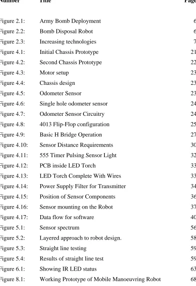
http://www.army-technology.com Figure 2.1: Army Bomb Deployment
Figure 2.2: Bomb Disposal Robot
A more closely related topic is the automatic vacuum cleaner. These units commonly use ultrasonic sensors to navigate around the room cleaning as it goes. Boundaries can be set using magnets and the unit is sensitive to drop-offs such as stair wells. A common example of this is Electrolux’s Trilobite which is now commercially available at retail stores.
State-of-the-art remote bomb disposal technology, the telerob Explosive Ordnance Disposal and observation robot tEODor. The German Army model is equipped with five cameras and a double shot disruptor type Richmond RE70.
[image:18.595.229.391.328.515.2]2.2 The Need for Autonomous Applications
Imagine never having to wash, iron, clean or cook again. A robot could do it all for you while you sit back and relax. To some this seems like the perfect world, while to others it seems unethical and truly against their beliefs. The demand for autonomous applications is becoming ever more increasing and public acceptance is also on the increase.
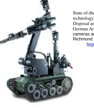
The company ‘Poly Micro’ argued in their 2004 newsletter that autonomous appliances will grow because of consumers increasing expectations of energy and water saving, noise reduction and overall efficiency and functionality. They also bring to focus that more technology is being accepted within society. The following graph from poly micros 2003 newsletter shows the acceptance of new technology relating to the automation of driving systems within a manned vehicle.
Poly Micro predicts that by 2010 autonomous driving will be largely accepted as practical by society. New cars of today are considered dangerous not to have an airbag whereas 20 years ago this technology was not heard of.
Although this data varies slightly from this dissertation work, the trend of need and acceptance through time is accurately portrayed in Figure 2.3.
[image:19.595.167.488.508.690.2]http://www.polymicro-cc.com/site/pdf/POLYMICRO-markets.pdf
The article “Appliances of the future’ states also that the need and expectations of this type of technology are growing at an alarming rate. It also mentions that for ideal autonomous work in the future that robots will need emotion such as fear, pride and caution. How can a robot complete great work if it has no pride in what it does, and how can it make decisions without a conscience?
Henrik Christensen suggests that autonomous robotics in the home is a great idea however has not come far enough to really break into the household market. The cost is simply too high in ratio to its functionality.
Overall it is evident that the need and acceptance for autonomous robots in the home is ever growing. While some circumstances of future developments may seem unethical the basic cleaning and entertainment robots are proving to be an accepted and sought after item in the home.
2.3 Sensing Distances in Applications
There are many different methods available for the purpose of sensing distances. These include sensors such as proximity, ultrasonic, infrared, magnetic and various others. Which of these is most suitable for a household application?
The Electrolux Trilobite (vacuum cleaner) uses ultrasonic sensors to navigate around the room. Most sensors work by emitting some form of light or frequency and waiting for that emitted source to ‘bounce back’. Ultrasonic sensors use sound or frequency whereas infrared uses an invisible light source to judge distance or proximity. Infrared light is often also used in data transmission such as remote control for a common television.
From all of these details it seems that a very successful method of judging proximity, and also possibly recognising distance, is to use an infrared LED (Light Emitting Diode) and an infrared detector. When the robot is facing a wall or object within a certain distance (unknown at this stage and variable) infrared light will reflect from that object and be collected in the detector. The higher the voltage or current returned from the receiver, the closer the object must be. To overcome the possibility of natural light, containing infrared, affecting the functionality of this sensor configuration, it will be necessary to clock the infrared emitter at a rate of 36 – 40 kHz. The receiver will also have to be tuned in order to only recognise this frequency of light.
2.4 Object Avoidance
Many applications are beginning to incorporate object avoidance technology into their design. Cars are becoming more autonomous, traction control for example, and this technology is bound to move towards object avoidance. Reversing sensors can alert the driver when an object is close to the rear of the vehicle. It is only a matter of time before a car will be able to recognise which lane it is and manage the steering system to ensure it does not cross any lines. This technology is sure to save many lives from the hazard of driver fatigue.
Object avoidance technology is currently installed into many items such as automatic vacuum cleaners, auto lawn mowers and other items where little human instruction is desired. Electrolux’s Trilobite automatic vacuum cleaner uses random driving while avoiding collision in order to cover the floor space.
A project conducted by a student at Niagara Technology University used sensors and hardware to create a object avoiding robot not dissimilar to that of this dissertation. The concept behind this project gave the robot a human like thought process in that it would come to an object, view the left then view right and make a decision of which way was best to turn. If the robot had cornered itself then it would turn around and continue driving.
perform this operation. The proposed algorithm is intended to create a logical path for a unmanned vehicle to take by use of sensors, videos and imaging data. ‘Our focus is to develop a object avoidance algorithm called SmartAvoidT that extracts multiple objects/targets out of video/imagery data, establishes individual tracks for each object and maps a path around each object to avoid collisions.’ (Tunnel D 2004). This algorithm would then be implemented into the vehicles navigation system in order to follow the calculated path. The algorithm will be designed to work in all weather conditions such as day, night, rain, smoke or any other condition.
Koren Ward suggests that a successful method of controlling object avoidance is for the robot to ‘learn’ methods and trends associated with traversing different situations. This concept still utilises sensors and logic however has another much more complex learning ability. The unit will record its previous experience with regard to the readings from its sensors and so will be able to make a decision based on what occurred last time. For example if sensor 1 was blocked and sensor 2 was clear then it will perform in the same way as it did last time as long as last time encountered no errors. If errors occurred it will try a different method and compare the results. This is a very complex concept however it would most likely produce the least amount of errors in the long run. A basic logic system may encounter the same error repeatedly, whereas this use of a fuzzy logic learning system should prevent this occurrence.
While there are several methods of controlling a robot to avoid objects many are much too complicated for the general purpose of this dissertation. This dissertation aims to create a base model of an autonomous robot and so the programming of object avoidance will be kept to a simple level. The concept described by the technology student above is the initial concept decided upon for this dissertation. Giving the robot a set of hard coded rules once it reaches an object should give satisfactory performance while maintaining a simpler approach.
If yes turn left
If no, is right sensor clear? If yes turn right
If no then reverse out or turn 180 degrees Continue in a straight line (loop to START)
2.5 Dual Motor Drive Systems
Many systems use dual motors for directional control. A dual motor drive system refers to having one motor for each drive wheel also known as ‘differential drive’. Both motors driving forwards will make the unit move forwards; one motor forwards and one motor in reverse will result in the unit turning etc. A well known example of this drive system is in a skid steer (commonly known as a Bobcat). This method gives excellent directional control and ‘on the spot’ turning allowing for tight corners and superior manoeuvrability. The major problem with this method however is that one motor will always turn slightly faster than the other resulting in the unit driving in a slight curve. This may be due to efficiencies in the motors, gearbox friction, wheel to ground friction and other uncontrollable factors. Some form of odometry for each wheel will be necessary to ensure that the unit manoeuvres in a straight line.
This issue of non-straight driving is very common among robot builders and has been overcome in several different ways. Many choose to change the drive system to a more car like drive system with a single drive motor and steering mechanism. This is not practical in many cases as it will sacrifice functionality. The problem has been overcome before by pulse-width modulating the two drive motors and counting the edges on the encoders located at each wheel. This seems to be a very successful method.
rotate unless the motors turn at different speeds. By monitoring the differential with a sensor algorithms can be written to control the navigation.
For the purposes of this dissertation the clearest method is to use sensors on each wheel, or better yet on the actual drive motor, to measure the revolutions and therefore distance travelled. An algorithm will be written to ensure both drive wheels rotate at the same speed.
This method will become very useful if time permits to increase the robots performance. If this goes ahead the robot will use a method known as ‘dead reckoning’ where it calculates its position as a sum of how far and in what direction it has travelled since its origin. Although this is a rather inaccurate approach it is far simpler than any Global Positioning Systems (GPS), especially in such a small application.
2.6 Consequential Effects and Outcomes
The final outcome of this project provides a base model for intelligent household applications such as cleaning, object retrieval or similar. The extent of this project will not extend to a final product suitable for marketing but is just the base concept.
The research and technical outcomes from this project pose no direct ethical or legal dilemmas however if this concept is extended on then some factors may need to be considered.
Many engineers and scientists are still studying the use of autonomous vehicles for many different purposes in many different fields of expertise. From military through to agriculture robots are becoming more frequently relied on and the need for more advanced technology is ever increasing.
Although most of these cases still rely on human instruction, usually from remote control, they are all still based on a similar content to the technical side of this dissertation.
Future development of this idea of autonomous mobile navigation may result in any number of new designs. Some of these may be:
• Concept cars able to drive without human instruction. May be used for taxi services or courier and mail delivery.
• A similar service to ‘Guide dogs for the blind’, helping blind members of the community to be self sufficient.
• Automatic cleaning of bathrooms, kitchens and offices. Reducing the need for maids and cleaners.
Some of these future developments pose some ethical questions however. Is it right to make a machine that will put people out of work? What if the automated robot causes damage to humans or property and is not able to be controlled? What if an automated car crashes, killing a family with young children? Who takes the blame for any of these circumstances? It is a very controversial subject with many sides to each argument.
2.7 Summary: Chapter 2
CHAPTER 3
RESEARCH DESIGN AND METHODOLOGY
Before commencing any of the construction or completed design of any of the electronic or mechanical components, it was necessary to undertake some certain analysis. A safety analysis and a resource requirements and acquisition table was completed to fully understand the background, direction and precautions to consider whilst the project was under design and analysis.
3.1 Safety Issues
Safety is a relatively low concern in this project. While various factors require some attention, there are no large definite risks such as chemical handling. Saying this however does not mean that there is no cause for concern along the duration of this project. The following risk assessment outlines the primary hazards and methods of reducing the risk.
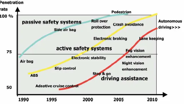
Constructing anything mechanical brings with it some risks. The construction of this mechanical unit involves cutting, grinding, drilling and using other power tools on products such as aluminium and timber. Bushes are also to be made from industrial grade plastics on a lathe. On the electrical side of this project a lot of soldering and drilling/screwing will also take place. The possible hazards and risks of these operations are listed below.
3.1.1 Mechanical Safety Issues
Cutting aluminium with drop-saw or similar
Hazard Occurrence likelihood Consequence H/M/L Controls to avoid injury Risk after controls Loud Noise High- Aluminium is a noisy material to work with
H – Hearing Damage will occur for multiple cuts
Hearing protection must be worn
L – Small amount of cuts no problem.
Flying debris
High – Hot spatter from saw blade will fly
H – Blinding if caught in eyes, minor burns possible on skin
Eye protection to be worn, Face mask preferable, non-loose – long sleeved clothes
L – Adequately protected
Saw jamb
Medium – If work not secured piece may fly
H- possible loss of fingers in blade or pinching of skin
Clamp work piece when cutting
L – If clamped no problem
When grinding, ensure that the appropriate sized grinder is used. For example, a nine inch angle grinder used on a small piece of aluminium is likely to cause damage to either operator and/or work piece.
Grinding/ Die grinding
Hazard Occurrence likelihood Consequence H/M/L Controls to avoid injury Risk after controls
Loud Noise High- Grinding is a noisy operation
H – Hearing Damage will occur for long use
Hearing protection must be worn
L – Small amount of cuts no problem.
Flying debris High – Hot sparks from blade
H – Blinding if caught in eyes, minor burns possible on skin
Eye protection to be worn, Face mask preferable, non-loose – long sleeved clothes
L – Adequately protected
Grinder jamb
Medium – If work not secured piece may fly
H- possible loss of fingers in blade or pinching of skin
Clamp work piece when cutting, use appropriate grinder
L – If clamped no problem
Table 3.2: Grinding and die grinding safety
When using any power tool ensure correct tools and attachments are used and appropriate user knowledge of the operation is known.
Drilling and other power tools
Hazard Occurrence likelihood Consequence H/M/L Controls to avoid injury Risk after controls Loud Noise
Med – most power tools create some loud noise
M - Hearing Damage will occur for multiple cuts
Hearing protection must be worn
L – Small amount of cuts no problem.
Flying debris
High – Hot spatter from saw blade will fly
H – Blinding if caught in eyes, minor burns possible on skin
Eye protection to be worn, Face mask preferable, non-loose - long sleeved clothes
L – Adequately protected
Tool jamb
Medium – If work not secured piece may fly or spin
H- possible loss of fingers in blade or pinching of skin
Clamp work piece during work
[image:28.595.143.510.136.284.2]L – If clamped problem minimised
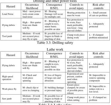
Table 3.3: Drilling safety Lathe work
Hazard Occurrence likelihood Consequence H/M/L Controls to avoid injury Risk after controls Flying debris
High – Hot spatter from saw blade will fly
H – Blinding if caught in eyes, minor burns possible on skin
Eye protection to be worn, Face mask preferable, non-loose - long sleeved clothes
L – Adequately protected
High speed operation
M- Chuck and work piece spinning
H- loss of fingers of large cuts and abrasions
Experienced user present, caution used when operating
M- Impossible to remove spinning component
Work piece fly M- chuck slip or error in clamping
H- building damage or personal injury
Ensure piece clamped, be aware of possible piece release
M- Impossible to reduce risk to a low level.
Saw jamb
Medium – If work not secured piece may fly
H- possible loss of fingers in blade or pinching of skin
Clamp work piece when cutting
L – If clamped no problem
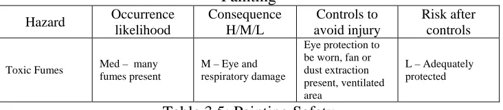
[image:28.595.142.513.355.708.2]Painting
Hazard Occurrence likelihood Consequence H/M/L Controls to avoid injury Risk after controls
Toxic Fumes Med – many fumes present
M – Eye and respiratory damage
Eye protection to be worn, fan or dust extraction present, ventilated area
L – Adequately protected
Table 3.5: Painting Safety
3.1.2 During The Electrical System Creation:
Soldering
Hazard Occurrence likelihood Consequence H/M/L Controls to avoid injury Risk after controls Toxic Fumes
Med – many fumes present raising upwards
M – Eye and respiratory damage
Eye protection to be worn, fan or dust extraction present, ventilated area
L – Adequately protected
Hot solder
dripping Low
M- Mild burns to skin
Clear work area in standing position. Adequate clothing
L- Caution will mean no burns
Hot iron
Med. Touching will leave instant burns
M – Possible mild burns
Clear work area and use caution
[image:29.595.145.511.82.162.2]M – unavoidable other than caution used
Table 3.6: soldering safety
3.1.3 During The Testing Procedure:
Although testing seems very straight forward, there are still several hazards to be aware of. User hazards are minimal however damage to hardware and property is still possible.
Testing
Hazard Occurrence likelihood Consequence H/M/L Controls to avoid injury Risk after controls Object avoiding fails
M- sensor fail, code error
L – small scratches on objects
Use test blocks which can be hit
L- no damage will be caused Overload or short
circuit microcontroller
M – surge in power or error in connection
H – Expensive microcontrollers Careful connections, use overload protection L- microcontroller protected
Power sources Med – voltage shocks
H – if large voltage touched,
electrocution possible
Understand power pack before use. Tape or hide high voltage wires
L- High voltages avoided.
Table 3.7: Testing safety
3.2
Resource Requirements
The required resources can be categorized into two major fields, mechanical and electronic. The following explains these categories and the planned source.
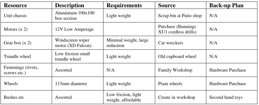
Mechanical components/resources:
Resource Description Requirements Source Back-up Plan
Unit chassis Aluminium 100x100 box section Light weight Scrap bin at Patio shop N/A
Motors (x 2) 12V Low Amperage Purchase (Bunnings
XU1 cordless drills) N/A
Gear box (x 2) Windscreen wiper motor (XD Falcon)
Minimal weight, large
reduction Car wreckers N/A
Trundle wheel Low friction small
trundle wheel Light weight Old cupboard wheel N/A Fastenings (rivets,
screws etc.) Assorted N/A Family Workshop Hardware Purchase
Wheels 115mm diameter Light weight Pram wheels Hardware Purchase
Bushes etc Assorted Low friction, light
weight, affordable Create in workshop Second hand toys Table 3.8: Mechanical resources
Electronic components
Although there will be many components required that are unknown at this stage, the following table provides a basic plan for the sourcing of components.
Resource Description Requirements Source Back-up Plan
Microcontroller Motorola HC12 - - - USQ on loan Purchase chip and get
soldered to PCB
Infrared LED + sensors Various - - - Electronic shop Internet purchase
555 timers - - - - - - Electronic shop USQ loan
[image:30.595.107.547.166.345.2]Wiring Various colours - - - Electronic shop USQ
Table 3.9 Electronic Resources
3.3 Sustainability
At the conclusion of this project several components will be returned. The microcontroller will remain the property of USQ. The windscreen wiper motors will be beyond repair but may be reused in other applications. Wheels and other mechanical components will be returned to the workshop. The electronic components will be kept for other applications where sensors etc can be used.
3.4 Methodology
The following project goals were created in chapter one and are re-listed in methodology so as to set the basis for the structure of this dissertation. The project work outlined in this dissertation is based entirely around this methodology.
By pursuing the following goals the project objective should be reached satisfactorily and efficiently.
1. Define a guideline to assess the performance of the robot to the specifications of the project objective.
2. Build a prototype that is practical to the objective
3. Research the background behind obstacle avoidance and other attempts to achieve similar tasks.
4. Research microcontrollers and sensors to acquire the most practical configuration as to meet the objective.
5. Define an initial design of the configuration and code to be implemented.
6. Construct initial design
7. Test and analyse the results in accordance to the performance guidelines.
8. Re evaluate the design as required to achieve the project objective.
As time permits
o Define a new performance guideline for the practical task completion o Research more methodology if required
o Re design and construct the robot to achieve the new objective.
3.5 Justification of Methodology
The methodology above has been chosen carefully to complete the project objectives. The first step of ‘Define a guideline to assess the performance of the robot to the specifications of the project objective’ has been chosen to give the robot a set of guidelines to be assessed against. Without having this goal, it will be impossible to determine if the robot has met all requirements. Goal three, Research the background behind obstacle avoidance and other attempts to achieve similar tasks, will give background knowledge behind the concept. This can save a lot of time in decision making processes as it may help predict the outcomes based on previous experiences. The design stage is the next logical step and is carried out as goal four. The testing stage is very important and is closely linked with goal one of the performance guideline. The robot must be tested and assessed against these guidelines in order to understand which parts of the robot were successful and which aspects need more work.
CHAPTER 4
Construction and Design
4.1 Initial Design
Several ideas were analysed before the initial prototype was built. The mechanical structure of the robot was a major consideration. Wheels versus tracks, mechanical steering versus dual motor drive and other considerations along with shape and dimensions were the chief factors.
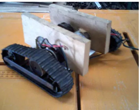
[image:33.595.210.444.383.569.2]Initial analysis of these ideas provided a dual motor, two track setup with a wide wheel -base for stability. This design is shown in figure 4.1 below.
Figure 4.1: Initial Chassis Prototype
The motor slipping in the tracks would have made this project a near impossibility without a delicate error correction system in place. Because of these difficulties a decision was made to use wheels connected as a direct drive to the motor.
4.2 Second Prototype
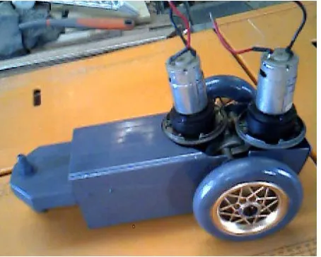
[image:34.595.214.441.299.481.2]The second prototype for the mechanical design consisted of an aluminium chassis with dual drive motors. A simple trundle wheel for stability was used to allow ‘on the spot’ steering and high manoeuvrability.
Figure 4.2 Second Chassis Prototype
Figure 4.3: Motor setup Figure 4.4: Chassis design
The chassis is a 100 x 100mm box section of aluminium commonly found on patio posts. The axle holes were formed with a die grinder and are designed for the motors to bolt straight into. The trundle wheel was placed on temporarily until final dimensions are known for extra hardware (batteries, microcontrollers, wiring etc).
4.3 Odometer Sensors and Interrupt Control
4.3.1 Building the odometer sensors
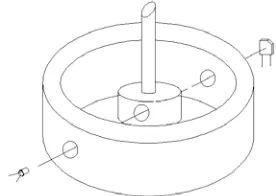
As explained earlier, it is necessary for the Mobile Robot to be able to drive in straight lines between obstacles. For this to occur it is necessary to calculate the turns of each wheel (or motor) to compare against the other. There are various methods available for this; however the easiest and most successful technique is to insert a sensor on each motor to count the revolutions. In this case an infrared LED and receiver have been used to count the revolutions. Figure 4.5 shows how this sensor is implemented.
[image:35.595.119.348.102.202.2] [image:35.595.114.476.551.702.2]The LED (DSE part number Z3235) and Infrared Receiving Diode (DSE part number Z1956) are mounted in an outer casing that mounts the motor to the gearbox. A 4mm hole is drilled through the motor drive shaft which aligns the LED with the Receiving Diode twice for every revolution of the motor. From this circuitry it is possible to obtain a 5 volt drop for every time the sensor is aligned.
Figure 4.6 Single Hole odometer sensor
To obtain the 5 volt drop it was necessary to fiddle with resistor values on the 5 volt input rail to the receiver. The resistor value was dependent on how much of the hole aligned, the intensity of the infrared beam coming through the hole and also the brightness of the outside light. (Incandescent light bulbs and sunlight contain masses of Infrared.) To overcome the variance of the outside light, a film of white gap filler was applied over the receiver to completely isolate all of the surfaces from any source of IR other than the emitter. A guess and check of values found that when a 68 kilo ohms resistor was placed in series in the power supply for the receiving diode, a five volt drop (5v to 0v) was obtained when the sensor aligned. See circuit below for details.
[image:36.595.189.492.555.707.2]4.3.2 Using interrupts to count odometer readings
The circuitry detailed earlier was designed to provide a 5v drop twice for every revolution of the motors shaft. This 5 to 0 volt drop provides the perfect setup to use in one of the many Motorola HC12 interrupts.
The Motorola has many different interrupts with varying priorities and ideal uses. Some forethought was applied to the needs of interrupts and it was considered that the odometry sensors would need the highest priority. This would allow other lower priority interrupts to run without effecting the counting of motor revolutions. A first attempt was to use IRQ and XIRQ to count each motor.
[image:37.595.220.430.506.745.2]The first issue to deal with using this decision was that XIRQ is a level sensitive interrupt. This meant that if the motor was rotating slower than the interrupt could service (and obviously this would happen with an 8Mhz processor and the robot only moving at about 0.2m/s), then the interrupt would run repeatedly whilst the IR LED and the Receiving Diode where in line. To overcome this, a flip flop was set up to trigger on the falling edge of the signal and then it would be reset by a wire coming from Port A. The concept behind this seemed logical and straight forward however many problems arose for various reasons. Figure 4.8 shows the Flip Flop configuration implemented.
The above arrangement of a 4013 Dual D Type Flip Flop is set to work on a rising edge (0 to 5 volts). Using a falling or rising edge will not affect the accuracy of the counting; it will still see two rising edges every rotation of the motor. When the sensor rises from 0v to 5v, the flip flop is triggered and Q NOT changes from high to low which triggers the XIRQ (active low) interrupt. Before the end of the interrupt service routine, a logic high can be sent from PORT A to reset the flip flop and await the next rising edge from the sensor.
This concept did not work when attached to the sensor and microcontroller. When voltages where manually applied to the flip flop slowly it would perform successfully however when the process was applied through the XIRQ interrupt service routine, the logic levels would not change appropriately. The IRQ interrupt was also not working correctly. It was initialised to recognise falling edges but would not activate on the falling edge coming from the sensors. It would however activate if an earth wire was touched to it. It was decided that perhaps noise or other less obvious factors were causing this.
There seemed to be too many problems for the simplicity of this idea so it was deemed appropriate to disregard the use of XIRQ and IRQ for this purpose. The sensor wires were connected to the PORT G key wake up port and instantly an accurate counter was achieved. The major issue with this arrangement was to remember not to use any higher priority interrupts to run a routine which would turn the motors in either direction. This would make the position of the robot an unknown factor.
4.4 H-Bridge Motor Control
[image:39.595.119.537.280.620.2]After having the mechanical unit constructed, encompassing the microcontroller and odometry sensors, it was necessary to decide on a method to control the motors. Two H bridges were sourced from the technician’s lab at USQ to allow the microcontroller to handle the large current flows. An H bridge works by a series of four switches which can control the current flow through the motor. The schematic below shows the basic operation of the common H Bridge. The grey arrows represent the current flow through the motor.
Figure 4.9: Basic H Bridge Operation
Anything that can control a current is suitable for use as the switches in an H bridge such as relays, transistors or MOSFETS. In this case, four MOSFETS have been used with small heat sinks to cater for the 12V motors which are drawing approximately 2.5 amps each at full load.
One excellent advantage of using an H Bridge is that it reduces the voltage and current spikes that occur from the motors starting, stopping or changing direction quickly. With the Mobile Manoeuvring Robot the voltage spikes were still higher than the H Bridge could contain. The cheap motors that were purchased for the drive have very poor characteristics and were resetting the microcontroller every time that the two motors turned on simultaneously. There are several procedures that could have been undertaken to overcome this problem. A more efficient pair of motors may have produced less voltage spike; a large capacitor could have been implemented to provide a spike filter; or the chosen method, to use separate power supplies to run the microcontroller and the motors respectively. A 9 or 10 volt battery is ideal for running the microcontroller as the voltage passes through a LM7805 voltage regulator. This method has the added advantage of being able to have a separate, higher voltage battery to run the motors without having to reduce it significantly to power the microcontroller. Both power supplies must share a common earth for the robot to function correctly.
To control the motor speed requires more than just a logic high input to the H Bridge. Motors will always run at slightly different speeds due to the internal friction losses and other variances in efficiency and so the robot would drive in large circles. Pulse Width Modulation (PWM) is a very successful method of controlling the speed. By applying a chosen frequency to both motors and then adjusting the duty cycle, the motors speed can be controlled. The Motorola HC12 has 4 channels dedicated to pulse width modulation. Bits 0-3 of PORT P can easily be set to output a controllable pulse. This provides a perfect environment to control two motors, one channel for each motor in each direction.
control the frequency. By setting a number between $01 and $FF in the PWPER (0-3) registers, the pulse frequency can be set to a proportion of this clock rate. The duty cycle of this frequency can then simply be controlled by storing values between $00 and $FF into the PWDTY (0-3) registers. This value represents the proportion of high over low time; hence $FF/2 would be 50% duty cycle and the motor would be running at half speed, or $00 would stop the motor.
It is important to not switch the H Bridge switches too fast in this application. Transistors require a small amount of time to switch on or off. It is because of this time that causes a current flow and hence a power loss. Over switching at high frequencies will increase the power consumption and therefore create heat from the MOSFET’s. Heat sinks are installed on all of the robots MOSFET’s to compensate for the switching power loss.
To conclude on motor control, the Mobile Manoeuvring Robot is controlled by two identical H Bridges which are powered from a 10 – 12 volt source. The motor speed is determined by four separate Pulse Width Modulation Channels with a relatively low but fixed frequency and variable duty cycle.
4.5 Infrared Distance Sensors
4.5.1 Requirements and Availability
The current market offers many types of sensors for use in various applications. A few of the major types of sensors include:
• Optical sensors
• Photo diode sensors
• Fibre optics sensors
• Proximity sensors
For accurate manoeuvrability in this application it is necessary that the sensors have a long enough range to avoid collision during turning. Figure 4.10 illustrates this need.
Figure 4.10 Sensor Distance Requirements
The above diagram illustrates that even after the robot has stopped to avoid an object, the turning circle will result in the corner of the robot still proceeding forwards. It is necessary for the sensor to be able to read further than this turning circle. The necessary distance can be reduced significantly by turning the outside wheel backwards so it pulls away from the wall, this however does pose the issue of being able to reverse into objects, as there is no rear sensors.
Also, when in this illustrated position, it would be preferable if the sensors could judge a long distance at the sides of the robot. If the robot where to turn left after stopping in figure 4.10, it would turn directly into a wall and be interrupted by the side sensor half way through a turn. This would make coding of the processor more difficult. Initial experimentation has shown the ideal range of the sensors will be approximately 200mm-300mm but definitely no less than 100mm for the front sensor.
4.5.2 Choice of Sensor
Almost all of the current household applications that require distance or proximity sensing utilise Ultrasonic or Infrared Light (IR) sensors. The market available choices are large and vary in specifications and range in price from around $40 - $120 each. Many hobbyist robot builders choose to construct IR sensors to save a lot of cost and custom design them to suit the necessary requirements.
For the purpose of the Mobile Manoeuvring Robot, it was decided to construct three separate Infrared Sensors from parts commonly available at electronic stores.
4.5.3 Design and Construction of IR Sensor
The design and construction of the Infrared sensors took a very large portion of the time and effort spent on this project. Lack of information on the chosen parts made it difficult to realise their true operations and many other factors postponed the successful creation of the sensors.
Figure 4.11: 555 Timer Pulsing Sensor Light
Initial calculated results differed substantially from the measured performance. It was necessary to connect a Cathode Ray Oscilloscope (CRO) to accurately measure the waveform output. Slight tuning of resistor values provided an accurate 38 KHz square wave with 50% Duty Cycle.
The transistor is required on the output of the 555 timer to source the current needed to supply the three IR LED’s. Each LED can handle 50mA constantly running through them, however due to the 50% duty cycle; the LED will only be on 50% of the time. It can then be safely assumed that the LED’s can actually handle 100mA as long as they are only run through the 555 timers pulse.
Figure 4.12: PCB Inside LED Torch Figure 4.13: LED Torch Complete With Wires
The IR receiving diode should have responded with a voltage drop or even a noticeable resistance change when presented with the torch; however no change was found whatsoever. To check the frequency response of the chip, a function generator was hooked into the base of the transistor at the output of the 555 circuit. The chip was tested for response from 1 Hz up to a few hundred kHz but absolutely no response was found. No datasheet was available for this chip as it was sold solely and had no markings to distinguish it by. After reading other circuits that seemed to contain similar chips, it was found that a pull-up resistor was most likely necessary for correct operation. By adding a 2k2 ohm pull-up resistor to the output of the receiving chip a change of approximately 0.5V could be obtained over a distance of 100mm. This was far from ideal however a comparator circuit would be able to turn this small analog signal into a clear digital response. It wasn’t until the comparator circuit had been constructed on a breadboard that it was found that sunlight shining through a window was affecting the response of the sensor. Due to the large complexity of the comparator circuitry to achieve such a simple task, it was decided to scratch this idea and start from a different perspective.
[image:45.595.114.537.71.229.2]This was ideal for the purpose of the robot and so more of these chips were obtained. The Z1955 datasheet details a suggested bypassing and filtering circuit containing a few resistors and capacitors. A single circuit board was soldered containing three of these bypassing and filtering circuits and three receiving chips. Testing of these revealed that the first prototype circuit still worked fine, however the two new circuits (identical in every manner) would only work at a distance of approximately 20mm. Due to the fact that one of the receiving circuits worked successfully, the mistake was made of assuming that the IR transmitter circuit was without fault. It wasn’t until after many hours of testing and different circuitry being implemented that it was found to that the 555 timer circuit was causing relatively large voltage spikes in the power supply in time with the 38 kHz light pulse. Due to the fact that the emitter and receivers were being powered from the same voltage supply, the noise was affecting the operation of the receiver chips. It is still unsolved why one chip worked and the remaining two failed; however overcoming this problem initiated some desired results.
[image:46.595.119.537.528.637.2]A group of capacitors wired in parallel on the input of the transmitter circuit provided a noise filter to the power supply. A combination of a large Electrolytic capacitor, medium Tantalum capacitor and a small Monolithic capacitor provide an effective noise filter to combat fast ripples in the power supply. The following schematic details the chosen capacitors and placement in the power supply circuitry.
Figure 4.14: Power Supply Filter for Transmitter
The noise filter, illustrated in figure 4.14, reduced the noise to a negligible level. From this, the Z1955 receiving chips delivered a different behaviour. First experiments on the bread board provided three working receivers over a distance of approximately 300-400mm shown by a 5V drop. As this was suitable performance for the Mobile Manoeuvring Robot, the circuitry was soldered to a circuit board. Testing at a later date showed none of the circuits working again. After another long, strenuous testing period it was discovered that the Z1955 chips were also sensitive to sunlight and incandescent light, despite the claims of the data sheet. If an IR light source was provided to the robot, such as an incandescent bulb, the sensors would work successfully to a distance of approximately 300 mm. Without the additional IR light source the sensors would sometimes work at a distance of 20 – 30 mm.
To overcome this problem it was finally decided to implement some variable brightness IR LED’s to supply IR light to the back of the receiving chips. The Z3235 LED can handle at most 50mA constant current. A 1k variable resistor was implemented in series with a 100 ohm resistor so to provide a variable current which could not exceed 50 mA. Calculations prove that the current can be varied between 4.5 and 50mA:
(5) (100 0) 50 MAX MIN V I R V mA = = + Ω = (5) (100 1000) 4.55 MIN MAX V I R V mA = = + Ω =
Where: I = Current flowing through LED [Amps]; V = voltage drop across LED [Volts]; R = resistance in series with LED [Ohms].
Figure 4.15 gives an overview of how the pulsing IR LED, Receiving diode and variable IR LED are positioned to provide a successful distance sensor.
Figure 4.15: Position of Sensor Components
The Z1955 IR Receiver is mounted onto the torch containing the pulsating IR LED. This provides an ideal position to pick up any objects located directly in front of the sensor. A wider sensing range could be created by shortening the outer housing of the torch or using extra pulsating LED’s concentrating in the desired direction.
Figure 4.16 Sensor mounting on the Robot
There were two main options to communicate between the sensors and the microcontroller. Either the status wire from the receiver could be connected as an interrupt to the microcontroller; or it could be connected as a data line to any available port. Due to the fact that the robots guidance is more interested in knowing the current status of each of the sensors rather than knowing exactly when each is triggered, using the data line approach is far more effective. One advantage of this method is that noise filtering can be used by checking the sensor a number of times to ensure there is actually an object in front of the sensor and that the signal was not just caused by noise. After checking the sensors, the robot can make an informed direction on which direction to travel. Not using interrupts also allows checking of each of the sensors during any part of the code or in any interrupt service routine.
provide inverters. The logic signal from the sensors was then applied through these joined inputs and the output provided an inverted signal of the input.
The program code simply checks the status of each sensor in a loop by loading PORT A into an accumulator and performing logic decisions on the value loaded. The microcontroller now reads a logic one for an activated signal and a logic zero for a non-activated sensor. Hence, if all sensors are non-activated the register will read 00000111 or if no sensors are activated it will read 00000000.
To summarise the distance sensors used on the Mobile Manoeuvring Robot the following points can be observed.
• Infrared LED’s (DSE part number Z3235) clocked at a 38 kHz square wave with an even mark to space ratio are used for the transmission of the sensors light.
• Buffered Infrared receiver chips (DSE part number Z1955) with the recommended filtering and bypassing are used to pick up the transmitted light.
• Extra IR LED’s with variable brightness are used to saturate the IR receivers to ensure successful performance
• The logic outputs of the sensors are inverted to communicate effectively with the Motorola HC12
• Sensor status is read in by the microcontroller as data on PORT A.
4.6 The Software
The software used to control the Mobile Manoeuvring Robot was created in assembly language for the Motorola HC12. This allowed direct communication with the microcontroller and convenient access to all of its ports and functions. The software used to control the heading of the robot follows a relatively simple structure with small subroutines for each separable function or routine. Interrupts are used for the odometer counting and a tight loop in the main function keeps track of the direction of travel and sensor readings.
A software design procedure (available in Appendix C) was used to analyse the problem and deal with suitable specifications and provide an appropriate software structure. The software design procedure encompassed the major points of software design; such as objectives, user information and program structure. The objective of the software was stated to be “To control the mechanical hardware of a two drive-wheel robot in order to avoid collision with obstacles. The software must be able to control the unit to travel in
a straight line between objects and is based on assembly level language of the Motorola
68HC12 microcontroller.” It was necessary to base the software structure around this as well as encompassing the user information. The user information is listed below.
User Information
The code has five sensors that input to the software. Three of these are obstacle
avoidance sensors read in as data through port A and the other two are concerned
with odometer readings read in as interrupts through port G. The program starts at
$0400 with data starting at $0200. The stack pointer must be set in a clear location
such as $0700 and the program counter to $0400 to start the procedure.
When run, the program will output through the serial port the status of the odometer
readings and also controls the speed and direction of both motors to achieve the
desired performance. The program loops continuously to give real time control the
mechanical components
Robot. It is in the form of a tight loop main routine that branches out when individual activities require to be completed. The following outline was created to establish the necessary activities to be completed in the main loop and the appropriate related subroutines.
While driving do the following:
• Read the odometer sensors and increment odometer counters
o Check odometer counters and adjust speed for straight driving • Watch obstacle sensors in a tight loop act accordingly when sensors
triggered.
o If left is clear, turn left otherwise turn right If left and right blocked, reverse • Continue on a straight path
• Output data through serial port for debugging purposes • Repeat process continuously
[image:52.595.142.550.486.589.2]The data will flow as follows, coming from the five IR sensors and being manipulated and processed to obtain the required drive on the motors. There are four main processes that take part in this data processing.
Figure 4.17: Data flow for software
Process 1:
This is the main section of the program. It runs a tight loop checking for data from the sensors on port A and also checking the odometer readings to initiate a
PORT A Obstacle Odometer readings Process 1 MOTOR CONTROL
Process 3 Process 4
D1 = Signal of which direction to turn D2 = odometer counters
D3 = motor information for turning D4 = motor information for drive straight D5 = jump to process 4 when required
Process 2:
Process 2 is a large subroutine called every time a turn is needed. It accesses data from port A. It checks sensors and turns relative to their status. After the motors have been adjusted to gain desired performance the code returns to the main loop, process 1.
Process 3:
This is an interrupt service routine that determines which odometer sensor has triggered and increments the respective counter. The counter is a byte stored in memory and is cleared regularly to avoid overflow issues.
Process 4:
This process is a subroutine used to maintain straight line driving. It is called from the main program loop and works by comparing the odometer counters and adjusting motor speeds to maintain a constant even speed between the motors. This results in even wheel speed hence straight driving.
The above set-out of structure and processes has allowed the following code to be written and implemented into the Mobile Manoeuvring Robot. The next sections will break the code down into segments and subroutines and detail the operation of each function. From this, the code can be easily understood and modified to suit similar purposes. A full code listing is available in Appendix B.
4.6.1 Address Definition
“ ;ADDRESS DEFINITION
PORTA equ $00 ;Port A Data
PORTB equ $01 ;Port B Data
DDRA equ $02 ;Port A Data Direction
… … …
ADR16L equ $1FD ;
ADR17H equ $1FE ;
ADR17L equ $1FF ;
This section of code is simply written to show and name all of the available addresses of ports etc inside the Motorola HC12. Credit for this section of code goes to Mr Terry Byrnes. The rest of the program then references these address names for ease of reading, understanding and debugging. For instance the code to output hexadecimal 10 would be MOVB #$10, PORTA
This is much easier to understand than a code that says
MOVB #10, $00
Without knowing the addresses of every single port it would be near impossible to decipher the assembly language code.
4.6.2 Variable Definition
The next step in the code is variable definition. This simply defines all of the variables that will be used throughout the program and defines a location for their storage in memory. The variables start at address $0200 and list onwards from this address.
;*************VARIABLE DEFINITION***********************************
ORG $0200 START DEFINITION AT ADDRESS $0200
ODMA DC.B 0
ODMB DC.B 0 ;DEFINE VARIABLES
COUNT DC.B 0
4.6.3 Main Program
After variable definition is the main program control loop. This section is responsible for initialising all of the hardware and ports. The bottom tight loop is responsible for ensuring the robot drives straight and also that the sensors are checked frequently for object detection.
;**************MAIN PROGRAM..CONTROL LOOP************************
;NOTE: NO ACTION WILL OCCUR UNTIL THE IRQ INTERRUPT IS ACTIVATED UNLESS
CLR COPCTL ;DISABLE COMPUTER OPERATING
NORMALLY WATCHDOG
JSR INITSC0 ;INITIALISE SERIAL PORT
JSR INITKWG ;INITIALISE PORT G
JSR INITPWM ;SET UP PULSE WIDTH MODULATION ON
PORT P
JSR INITIRQ ;INITIALISE IRQ INTERRUPT
JSR INITPA
WAIT BRCLR PORTA,$01,SKP ;CHECK FRONT SENSOR AND IF ON
BRANCH TO TURNL
JSR TURNL
SKP LDAA COUNT
CMPA #$5A ;HAS MOTOR A COUNTED xx TIMES YET
(xx/2 REVOLUTIONS)
BMI WAIT ;IF NOT ,WAIT AND CHECK AGAIN
JSR COMP ;IF SO JUMP TO COMP (compare function)
BRA WAIT ;AFTER COMP GO BACK AND WAIT FOR
ANOTHER xx/2 REVOLUTIONS
The main loop code runs indefinitely until the reset button on the microcontroller is pressed or the power source is interrupted. Firstly it checks port A to determine whether the front sensor is triggered. If port A shows the front sensor has been triggered the program branches out of the main loop to the turn left subroutine. This subroutine will be explained further on. If the sensor does not show to be triggered the main loop continues on to check how many times it has been since the odometer was serviced. It does this by loading the number of revolutions motor A has turned and comparing it with a set number, currently $5A. This number can be adjusted to alter the performance of the robot. If motor A has not turned $5A counts, the main program branches back to the start of the loop and continues checking the sensor followed by the odometer counters. Once motor A has turned $5A counts, the main loop branches to the subroutine ‘COMP’ which compares motor A counts with motor B counts and adjusts the motor speeds accordingly to achieve straight line driving. This subroutine will also be detailed later.
4.6.4 DRFWD Drive Forward Subroutine
applies to the motor to be run. The byte moved is between $00 and $FF and is the percentage high time of the duty cycle of the pulse used to control the speed. A value of $FF will be full time on, hence maximum speed, and $00 will be full time low, hence not moving at all. The value $A0 has been chosen from physical observation to define the desired speed as smooth but reasonable pace.
*************DRIVE FORWARDS*********************************************
DRFWD MOVB #$A0, PWDTY0 ;DUTY CYCLE FOR CHANNEL 0|
MOVB #$A0, PWDTY2 ;DUTY CYCLE FOR CHANNEL 2| **DRIVE
FORWARDS
RTS ;RETURN FROM SUBROUTINE
4.6.5 Turning subroutines
The subroutines used to turn in either the left or right direction are very similar and hence only one subroutine will be detailed. The TURNL code is explained in the following.
Before the robot will turn left, several sensors are checked to ensure the turn signal was not generated by noise and also to ensure there are no objects in the direction of turn. Firstly the front sensor is checked repeatedly to ensure it is definitely set and that the signal was not generated by noise. This is done by loading a number into index register X and then looping that number of times, checking the sensor and decrementing X each loop. If at any time the sensor does not read triggered, the instruction to turn left will be aborted and the program will return to the main loop. Once the loop has been executed X times and is guaranteed to be a legitimate turn request, the left sensor is checked to ensure there is room to turn. If the left sensor is clear the code proceeds with a left turn. If not clear the code branches to the turn right subroutine.
commands a delay is implemented to reduce some of the jerky motion. The delay subroutine is used to create this delay.
;********TURNING CODES******************************************************
TURNL LDX #$0A00
LP BRCLR PORTA,$01,FALSE ;|
DEX ;LOOP TO CHECK SENSOR $0A00 TIMES
TO ENSURE NOT JUST NOISE
BNE LP ;|
BRCLR PORTA,$04,SKR ;IF LEFT SENSOR(3) BLOCKED, TURN
JSR TURNR ;RIGHT INSTEAD
SKR LDAA #'L'
JSR TXBYTE
MOVB #$00,PWDTY0 ;|
MOVB #$00,PWDTY2 ;|STOP MOTORS
JSR DELAY ;WAIT FOR DELAY PERIOD
MOVB #$00,ODMA ;|
MOVB #$00,ODMB ;|CLEAR ODOM COUNTERS
MOVB #$80,PWDTY1 ;TURN MOTOR B BACKWARDS
CONTL LDAA #$00
LDAB ODMB
CPD #90 ;SET NUMBER RELATIVE TO A 90 DEGREE
TURN
BLT CONTL ;WAIT FOR TURN TO COMPLETE