DESIGN AND DEVELOPMENT OF BATTERY-LESS ELECTRONIC FLOOR BASED ON HUMAN FOOT STEP IMPACT FORCE
MUHAMMAD HIZRAL TAZEEF BIN ROZEMAN
This report is submitted in partial fulfillment of the requirements for the award of Bachelor of Electronic Engineering (Industrial Electronic) With Honors
Faculty of Electronic and Computer Engineering Universiti Teknikal Malaysia Melaka (UTeM)
Tajuk Projek
Sesi Pengajian
UNIVERSTI TEKNIKAL MALA YSlA MELAKA
FAKULTI KEJURUTERAAN ELEKTRONIK DAN KEJURUTERAAN KOMPUTER BORANC l'ENGRSAHAN STATUS LAPORAN
PROJEK SARJANA MUDA ll
..
~~
~
.
~~~
..
~
.
~
.
.
~~
~~
':>
.
~~~
~
..
<?.f
..
~~
.
~~
1.-:
.
~
~
~
.
.
.
.
...
.
B.£trl?.D14\ L f~ ~Asro o~tiUMAN
fOor
S
TEP
tMPr:la
... f()~o;···
I
\
I
~
I
/I
I
I
1
I
Sa ya
..
M.~ BA.~.~D.
....
tt.~.~~~
.
.
..
P.\
:L~
~.Y..
.
.
~~.
~
....
~
~
~~~
-
.
...
.
..
..
.
...
..
....
.
.
(HURUFBESAR)
mengaku membcnarkan Laporan Projek Sarjana Muda ini disimpan di Perpustakaan dengan syarat-syaral
kegunaan seperti berikul:
I. Laporan adalah hakmilik Universiti Teknikal Malaysia Melaka.
2. Perpustakaan dibenarkan membuat salinan untuk tujuan pengajian sahaja.
3. Perpustakaan dibenarkan membuat salinan laporan ini sebagai bahan pertukaran antara instilusi pengajian tinggi.
4. Sila tandakan ( ..J ) :
D
SL'LIT*D
TEIUIAD••'n))A.K TERHAD
Tarikh: ...
1tP
.
l.~
t
1!?
I1
·
*(Mengandungi maldumat yang berdarjah keselamatan atau
kepentingan Malaysia seperti yang tem1al..'Tllb di dalam AKTA RAHSIA RASMI 1972)
iv
v
ACKNOWLEDGEMENTS
“In the name of Allah, Most Gracious, Most Merciful”
First and for most, praise to Allah S.W.T, because of His blessing giving me the good health and opportunity to complete my final year project in order to graduate in Bachelor of Electronic Engineering (Industrial Electronic) with Honour. Special thanks go to my helpful supervisor, Associate Professor Dr Kok Swee Leong for the valuable guidance and advice who gave me the golden opportunity to do this wonderful project. He has guided me from the beginning of this project. Thank you for the time, understanding and patience to help me completing this project.
I also want to take this opportunity to express my gratitude to Universiti Teknikal Malaysia Melaka for giving me chance to undergo this Final Year Project as partial fulfillment for my Bachelor Degree. Thanks again to Universiti Teknikal Malaysia Melaka for providing me with a good environment and facilities to complete this project
vi
ABSTRACT
vii
ABSTRAK
viii
TABLE OF CONTENTS
CHAPTER TITLE PAGE
PROJECT TITLE i
DECLARATION STATUS OF REPORT FORM ii
DECLARATION iii
SUPERVISOR DECLARATION iv
DEDICATION v
ACKNOWLEDGEMENT vi
ABSTRACT vii
ABSTRAK viii
TABLE OF CONTENTS ix
LIST OF TABLES xii
LIST OF FIGURES xiii
LIST OF ABBREVIATION xv
LIST OF APPENDIX xvi
I INTRODUCTION
1.1 Project Overview 1
1.2 Problem Statement 2
1.3 Project Objective 3
1.4 Scope of Project 4
ix
II LITERATURE REVIEW
2.1 Introduction 6
2.2 Introduction to Piezoelectric 7
2.3 Flooring System 10
2.4 Energy Harvesting 12
2.5 Monitoring Pedestrian 14
III PROJECT METHODOLOGY
3.1 Introduction 16
3.2 Flowchart 17
3.3 Experimental Set-Up 19
3.4 Characterizing Piezoelectric 21
3.5 Circuit Design 22
3.5.1 Bridge Rectifier 22
3.5.2 Storing Element 25
3.5.3 Transmitter and Receiver RF Module 25
IV RESULTS AND DISCUSSION
4.1 Introduction 28
4.2 Optimum Resistive Load 29
4.3 Bridge Rectifier 33
4.4 Storage Capacitor 34
4.5 RF Transmitter and Receiver Circuit 36
x
V CONCLUSION AND RECOMMENDATION
5.1 Introduction 40
5.2 Conclusion 41
5.3 Recommendation 42
REFERENCES 43
xi
LIST OF TABLES
NO TITLE PAGE
4.2.2 Optimum resistive load without casing 10
xii
LIST OF FIGURES
NO TITLE PAGE
2.1 Piezoelectric Disk 7
2.2 Polarization of ceramic material piezoelectric effect 8
2.3 V-I graph of parallel and series connection [3] 9
2.4 V-I graph of parallel and series combination [3] 9
2.5 Dance Floor System generated from kinetic energy 10
2.6 Pavegen Tiles 11
2.7 Anatomy of an Energy Harvesting System 12
2.8 Image of high density of pedestrian 14
3.1 Set up the equipment 19
3.2 Piezoelectric casing (Bending Mechanism) 21
3.3 End of Product of the Bending Mechanism 21
3.4 Schottky Diode 22
3.5 Bridge Rectifier 23
3.6 Schematic design of the bridge rectifier 24
xiii
3.8 Storing Capacitor 25
3.9 Transmitter and Receiver module 25
3.10 Encoder and Decoder IC 26
3.11 Transmitter Circuit 26
3.12 Receiver Circuit 27
4.1 Actuator Impact Machine 29
4.2 Spikes of the impact of the machine on top of the piezo 30
4.3 Power vs Resistor optimum resistive load without casing 31
4.4 Power vs Resistor optimum resistive load with casing 33
4.5 Output graph of bridge rectifier 34
4.6 Charging and discharging capacitor 35
4.7 Transmitter Circuit on a Strip Board 36
4.8 Receiver Circuit on a Strip Board 36
4.9 Transmitter Receiver Circuit Result 37
4.10 Transmitter circuit connected to Storage Capacitor 37
4.11 Receiver circuit received the signal 38
4.12 Energy harvested observed via multimeter 38
4.13 Lighting up the LED 39
xiv
LIST OF ABBREVIATION
PZT - Piezoelectric Disk/Plate Type
AC - Alternating Current
DC - Direct Current
V - Voltage
I - Current
R - Resistor
W - Watts
u - Micro
K - Kilo
M - Mega
RF - Radio Frequency
TX - Transmitter
RX - Receiver
PCB - Printed Circuit Board
s - Seconds
kg - Kilogram
m - mili
xv
LIST OF APPENDIX
NO TITLE PAGE
A Datasheet of Piezoelectric 45
B Datasheet of Schottky Diode 46
C Datasheet of TX-2B and RX-2B 47
1
CHAPTER I
INTRODUCTION
1.1Project Overview
2
way to enhance the use of environmental energy around us. There are a lot of energy being wasted around us as we are not aware of.
The main reason of this project is to harvest the energy by using piezoelectric which is embedded in a floor. Piezoelectric tile is designed to capture the wasted energy and resources. The energy is harvested from the impact of human foot step, then this energy is stored in an energy storage device for further use. From the impact of human foot step, the energy stored in the capacitor will power up the load circuit which is the transmitter circuit to send a bit of data to the receiver circuit. The system comprises piezoelectric installed at a strategic location and a wireless data transmission system. This system could be one of the way as a monitoring system as every step on the piezo count and store to send the data wirelessly. It will benefit the opportunity to improve city walkability and is hoped to improve the transportation system based on the pedestrian traffic.
1.2Problem Statement
Advanced technical developments have increased the efficiency of devices in capturing trace amounts of energy from the environment and transforming them into electrical energy. In addition, advancements in microprocessor technology have increased power efficiency, effectively reducing power consumption requirements.
3
One possibility to overcome these power limitations is to extract (harvest) energy from the environment to either recharge a battery, or even to directly power the electronic device.
In doing this project, there are some problem that were faced during the completion of this project. One of them is to test the piezoelectric itself. The machine which is the actuator can only press one piezo at a time. So, the problem is when doing an experiment to test a combination of connection of piezoelectric. It cannot be done with the help of the machine thus it need to be done manually with real human impact foot step. There are a few questions that need to be answered which one of them is how many piezoelectric should be used in this project, what is the best rectifier diode that has less power requirement and low voltage drop. Furthermore, this project involved a wireless transmission of data. One of the intention of this project is where a power generated from the piezo will be go through the rectifier and the power will power up a transmitter to transmit the bit to be received by receiver. With this, come another problem which is to find a suitable transmitter and receiver circuit that has low power consumption and can be power up by the energy harvester.
1.3Project Objectives
This project is developed to accomplish certain objectives such as: • To design energy harvesting project by using piezoelectric.
• To develop an energy harvesting circuit converting AC to DC for power up electronic circuit.
4
1.4Scope of Project
The main purpose of this project is to build or to design piezoelectric flooring system where the floor is designed to harvest energy from human foot step impact. The scope of this project is divided into several parts which are components and equipment, limitation and application.
For the components and equipment part, piezoelectric is used which is bought in electronic shops and not being designed by me. The type of piezoelectric which is being used is the Lead Zirconate Titanate (PZT) disk/plate type. Where it is one of the world’s most popular piezoelectric ceramic materials, which make it happen to develop energy when stress is put on it. This project also includes rectifier circuit and amplifier circuit. The purpose of rectifier circuit for this project is to convert AC to DC as the output from the piezo is AC. The design of the circuit that is used is taken from the previous research and being re-design and improve to get better output from it. This project also need amplifier circuit as the output from piezo is very small and need to be amplify for further usage. All this circuit is being printed on PCB.
There is some limitation of this project’s prototype which one of them is that this project is limited to be test in the controlled area as in the lab. The designed is subjected to be a conceptualize design. Regarding also about the prototype of this project, it consists of one tile which is embedded with piezoelectric.
5
1.5Thesis Organization
This thesis organization describe about what are the topics discussed on each chapter of this thesis. Chapter 1 discussed about the introduction of the project where all the basic information regarding this project is been discussed. In chapter 1 also discussed about why this project been choose as well as the important elements such as problem statement, objective and scope of project.
Chapter 2 is the literature review where it discussed about the background study and previous researches related to this project. The findings about piezoelectricity is one of the element included in this section.
Chapter 3 is the methodology. In this section, it tells about the flow of this project from the start until the end of this project. The block diagram as well as the experimental set up regarding this project also included in this section.
Chapter 4 is the result and discussion where in this part it describes about the project result that has been done. It includes all the analysis related to this project. Furthermore, it also includes simulation and experimental result.
In the last chapter which is chapter 5 it tells about the conclusion and future recommendation for this project. What is achieved and what need to be improve for this project is also included in this section.
6
CHAPTER II
LITERATURE REVIEW
2.1Introduction
This chapter 2 will describe about the literature study which involved during completing this project. In this chapter, some research needs to be done to find theory and information that can be used in this project. Therefore, the previous related work was understood to complete this project. All the components used in this project were studied first before move to another step to make sure the understanding of the characteristic and behavior of the components is in line with the intended output.
7
2.2Introduction to Piezoelectric
[image:22.612.255.420.233.372.2]A piezoelectric is a device that measure the changes in pressure when force act on it. The word piezo itself means electricity resulting from pressure. It came from a Greek word which mean squeeze or press and electric or electron, which is also stands for amber – an ancient source of electrical energy [1].
Figure 2.1: Piezoelectric Disk
Figure 2.1 above shows the picture of a piezoelectric which is ceramic plate type. The piezoelectric effect is a molecular phenomenon which can be seen at the macroscopic level as a change in electrical potential that is created when a piezoelectric is deformed. The first research and experiment was conducted in mid 1800s by Carl Linaeus and Franz Aepinus. The observation and experiment was not truly understood and until it was continued by the French’s physicist, Jacques and Pierre Currie in 1880. The piezoelectric effect contained a special material property that exists in many single crystalline materials. An example of crystalline materials are Quartz, Rochelle salt, Topaz, Tourmaline, Cane Sugar etc. In addition, there are two types of piezoelectric effects, which are direct piezoelectric effect and converse piezoelectric effect. As mention earlier, for the direct piezoelectric effect, the electricity is produced when stress is applied to it. Whereas for the converse piezoelectric effect, stress/strain is produced when and electric field is applied.
Direct piezoelectric effect: D=eTS + αs E (2.1)
8
D is the electric displacement control, T is the stress vector, e is the dielectric permittivity matrix, cE is the matrix of elastic coefficients at constant electric field strength, S is the
stain vector, αs is the dielectric matrix at constant material strain and E is the electrical
[image:23.612.137.539.168.277.2]field vector.
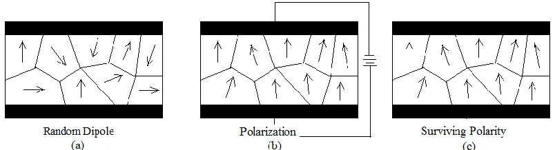
Figure 2.2: Polarization of ceramic material piezoelectric effect.
As what we already know, piezoelectric has the capability of creating a net voltage across the material when they are stressed. In [2] Initially, before the polarization electric dipole takes place, the direction of the molecules is randomly aligned where it is shown in figure 2.2(a). This phenomenon is happened in crystal which it is understood to has no center of symmetry [2]. When a strong electrical field is applied, the direction of molecules changes within the material which the electric dipoles re-orient themselves as shown in figure 2.2(b). When there is no electrical field, as shown in figure 2.2(c) the dipoles will maintain their orientation and the material then exhibit the piezoelectric effect. In regard to this, an electrical voltage can be recovered along any surface of the material when the material is subjected to a mechanical stress.
9
Figure 2.3: V-I graph of parallel and series connection [3].
Figure 2.4: V-I graph of parallel and series combination [3].
[image:24.612.218.439.265.407.2]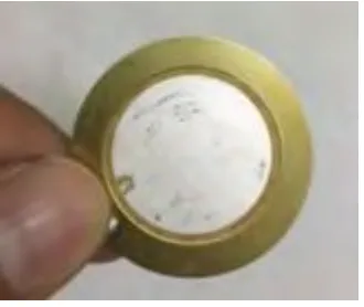
![Figure 2.3: V-I graph of parallel and series connection [3].](https://thumb-us.123doks.com/thumbv2/123dok_us/72869.6854/24.612.218.439.265.407/figure-v-i-graph-parallel-series-connection.webp)
