DEVELOPMENT OF MODULAR HULL OF A SUBMERSIBLE VEHICLE FOR
ENGINEERING SERVICES
IBRAHIM BIN MOHAMAD
A thesis submitted
in fulfillment of the requirements for the degree of Bachelor of Mechanical Engineering with Honours
FACULTY OF MECHANICAL ENGINEERING
UNIVERSITI TEKNIKAL MALAYSIA MELAKA
DECLARATION
I Ibrahim Bin Mohamad declares that this project report entitled “Development of modular hull of a submersible vehicle for engineering services”, under the guidance of Dr. Shamsul Anuar Bin Shamsudin, is my original work except references material.
Signature :
APPROVAL
I hereby declare that I have read this project report and in my opinion this report is sufficient in terms of scope and quality for the award of the degree of Bachelor of Mechanical Engineering.
Signature :
Supervisor : Dr. Shamsul Anuar Bin Shamsudin
DEDICATION
i ABSTRACT
ii ABSTRAK
iii
ACKNOWLEDGEMENTS
iv
TABLE OF CONTENTS DECLARATION
APPROVAL DEDICATION
ABSTRACT i
ABSTRAK ii
ACKNOWLEDGEMENTS iii
LIST OF TABLES vi
LIST OF FIGURES vii
CHAPTER 1 1
2.1 PROBLEM STATEMENT 3
3.1 OBJECTIVES 3
3.2 SCOPE OF PROJECT 4
CHAPTER 2 5
LITERITURE REVIEW 5
2.1 DESIGN AND CONSTRUCTION OF AN UNDERWATER VEHICLE 5
2.2 EXISTING DESIGN 5
2.3 STABILITY ANALYSIS 6
2.4 HYDRODYNAMIC FLOW 6
2.5 THE DEVELOPMENT OF NEW AUTONOMOUS UNDERWATER VEHICLE 7
2.6 PROPERTIES OF MATERIAL 7
CHAPTER 3 9
3.1 INTRODUCTION OF METHODOLOGY 10
3.2 GENERAL PROCESS 10
CHAPTER 4 12
RESULT AND ANALYSIS 12
4.1 DESIGNING BODY PARTS (CATIA) 12
4.1.2 SIDE FRAME 16
4.1.3 FRONT AND REAR PANEL 17
4.1.4 BOTTOM BODY (BASE) 18
4.1.5 THRUSTERS 19
4.1.6 ASSEMBLE PARTS 20
4.2 FINITE ELEMENT ANALYSIS (CATIA) 21
4.2.1 BOTTOM BODY FEA 21
4.2.2 REAR PANEL 25
4.2.3 FRONT PANEL 31
4.2.4 SIDE BODY 39
4.2.5 MIDDLE CYLINDER (MAIN BODY) 45
4.3 COMPUTATIONAL FLUID DYNAMIC 51
4.3.1 SIDE BODY 51
4.3.2 FRONT AND REAR PANEL 54
4.3.3 MAIN BODY 56
v
4.4 FABRICATING PARTS 60
4.4.1 REAR PANEL 60
4.4.2 FRONT PANEL 61
4.4.3 BOTTOM BODY (BASE) 62
4.4.4 SIDE BODY (FRAME) 63
CHAPTER 5 64
CONCLUSION AND RECOMMENDATION 64
5.1 CONCLUSION 64
5.2 RECOMMENDATION 65
vi
LIST OF TABLES
Table 1 Physical properties of Acrylic 8
Table 2 Mechanical Properties of Acrylic 8
Table 3 Electrical Properties of Acrylic 9
vii
LIST OF FIGURES
Figure 1 Underwater Vehicle By Tesla Offshore 17
Figure 2 Use of AUV for engineering services 17
Figure 3 Tuah Autonomous Underwater Vehicle 21
Figure 4 Flow Chart 28
Figure 5 Middle body frame 28
Figure 6 Flanges 29
Figure 7 O-rings 29
Figure 8 Dome cap 30
Figure 9 End cap 31
Figure 10 Side Body 32
Figure 11 Front Panel 33
Figure 12 Bottom Panel 33
Figure 13 Bottom Body 34
Figure 14 T-200 thruster 35
Figure 15 Assembly 36
Figure 16 Bottom Body 300N force compression 37
Figure 17 Bottom Body 200N force Compression 38
Figure 18 Bottom Body 200N force Tension 39
viii
Figure 20 Rear Panel 300N Force tension 41
Figure 21 Rear panel 180N Tension 42
Figure 22 Rear panel 300N force compression 43
Figure 23 Rear panel 200N force compression 44
Figure 24 Rear panel 90N force compression 45
Figure 25 Rear Panel 300N Force bending 46
Figure 26 Front panel 300N force tension 47
Figure 27 Front panel 100N force tension 48
Figure 28 Front panel 90N force tension 49
Figure 29 Front panel 500N force compression 50
Figure 30 Front panel 300N compression 51
Figure 31 Front panel 100N compression 52
Figure 32 Front panel 90N force compression 53
Figure 33 Front panel 300N force bending 54
Figure 34 Side body 300N force tension 55
Figure 35 Side body 150N force tension 56
Figure 36 Side body 100N force tension 57
Figure 37 Side body 300N force compression 58
Figure 38 Side body 200N force compression 59
Figure 39 Side body 100N force compression 60
Figure 40Middle cylinder body 200N force tension 61
Figure 41 Middle cylinder body 100N force tension 62
Figure 42 Middle cylinder body 500N force compression 63
Figure 43 Middle cylinder body 100N force compression 64
ix
Figure 45 Middle cylinder body 10N force load 66
Figure 46 Side body (side flow) 67
Figure 47 Side body (front flow) 69
Figure 48 Front and rear panel (side flow) 70
Figure 49 Front and rear panel (front flow) 71
Figure 50 Middle cylinder body (front flow) 72
Figure 51 Middle cylinder body (side flow) 73
Figure 52 Middle cylinder body (side flow) 2 73
Figure 53 Bottom body (front flow) 74
Figure 54Bottom body (side flow) 75
Figure 55 Acrylic rear panel 76
Figure 56Acrylic front panel 77
Figure 57 Acrylic bottom body 78
x
LIST OF ABBREVIATION
AUV Autonomous Underwater Vehicle FEA Finite Element Analysis
1
CHAPTER 1
INTRODUCTION 1.1BACKGROUND
Over the past few decades AUVs have matured from research and experimental vessels to commercially available systems. Commercially available AUVs are expensive and complex. Most AUVs are single hull systems with centralized electronics. With advancement in technology, newer sensors have been developed for a variety of operations which can be integrated in AUV systems.
With single hull AUVs it is not easy to integrate newer and upgraded sensors without making significant changes to the mechanical and electrical systems. This has given rise to interest in modular designs for AUVs. Modular AUV structures in hardware as well as software have significant advantages. Modules for different sensors can be made and interchanged to `configure the same basic AUV for different missions.
2
[image:16.596.163.472.290.390.2]To model the design process of pressure hull, a dedicated system based on VISUAL BASIC was developed. During the design process, the principle “simple, convenient and smart” is an essential step to follow. The patterns for calculating and checking were built by computer programming language. Using this system, the designer will get the results quickly and correctly. Figures 1.1 and 1.2 are the examples of an underwater vehicle and how it is used for engineering work
Figure 1 Underwater Vehicle By Tesla Offshore
[image:16.596.128.485.473.650.2]3
1.2PROBLEM STATEMENT
The highly cost and risky situation faced by the people that are involve in submersible and autonomous underwater robots encounters one general issue which is to come up with an effective and efficient solution for underwater missions. The intention of reducing the cost and risks produces opportunity for the communities practicing unmanned marine vehicles. This makes it possible to come up with a solution on how unmanned marine vehicles interact with users and other support systems, and how much work that they can manage on their own or working with other unmanned marine vehicle. The challenge is to develop a body that can withstand high pressure deep underwater without crushing the body and of course cause leakage that could gravely affect the robot in a whole. The challenge also took account the hydrodynamic features of the body. Therefore, a new and lower cost design requires a degree of certainty regarding all the challenges.
1.3OBJECTIVES
The objectives of this project are as follows:
1. To design and develop a modular hull of a submersible vehicle for engineering services.
2. To apply the knowledge of an engineering software CATIA by designing the modular hull of a submersible vehicle.
4 1.4SCOPE OF PROJECT
The scopes of this project are: 1. To conduct the literature review.
2. The process covers the full design in CATIA software which will be presented in this report.
3. The conduct drawing, strength testing analysis, and the hydrodynamics of the AUV parts using Ansys software.
5
CHAPTER 2
LITERITURE REVIEW
2.1 DESIGN AND CONSTRUCTION OF AN UNDERWATER VEHICLE
Autonomous underwater vehicle (AUV) has become a widely known topic used for industrial applications, military and of course to explore the ocean. Regarding that, AUVs has become one of the main option for underwater search or survey operations as they cost less than manned vehicles. Previous plans on developing an AUV focuses more on functional designs instead of identifying optimum designs. Through time, as the importance to minimizing the use of recourses (e.g. fuel, building cost, time for design etc.) becomes very clear, the approach of optimization becomes increasingly popular. (Khairul Alam, Tapabrata Ray and Sreenatha G. Anavattiet. al, 2013).
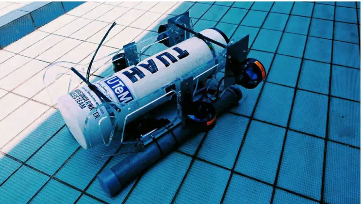
[image:19.596.124.496.498.709.2]2.2EXISTING DESIGN
6
The Figure 1.3 above shows the design of autonomous underwater vehicle named TUAH which is design by the students of University Technical Malaysia Melaka (UTeM). This AUV is used in the international robotics competition SAUV which stands for Singapore Autonomous Underwater Vehicle in the year 2017. Among all the contestant.
The AUV Tuah turns out to be the 3rd fastest vehicle during the qualification rounds. The design of the AUV in this project is roughly based on the design of TUAH’s but with an improvement being made.
2.3STABILITY ANALYSIS
The design of the body of an AUV needs to be stable underwater. The body needs to balance and must ensure that it does not disturb the electronic parts. Among all the electronic parts, the censor that is used to balance the AUV is called IMU. Its function is to balance the AUV, therefore the position of the AUV must be stable for the IMU to work efficiently. To make sure the quality of the data collected, underwater inspection mission requires an AUV with high stability, especially in roll and pitch direction. However, AUV with adopt torpedo- shaped body, has limited passive restoring moment in roll and pitch direction (Y.S Song et al., 2015).
2.4HYDRODYNAMIC FLOW
7
2.5THE DEVELOPMENT OF NEW AUTONOMOUS UNDERWATER VEHICLE
Among the development of new autonomous underwater vehicle focuses on an AUV that can travel for a long distance. It is called the next generation of AUV. The process of developing defines vehicle specification for the AUV to travel far distance. This includes the configurator, censor and water testing. The test to analyze the body includes the fluid property test and maneuvering control properties to examine the body before further developing it. (Ikuo Yamamoto et al., 2015).
2.6PROPERTIES OF MATERIAL
8
The information of the properties of acrylic is as shown in table below.
Table 1 Physical properties of Acrylic
Physical Properties
Metric
Density 1.18 - 1.19 g/cc
Water Absorption 0.130 - 0.800 %
Water Absorption at
Saturation 0.650 - 2.60 %
Moisture Expansion 0.500 %
Moisture Vapor
[image:22.596.59.526.333.745.2]Transmission 55.0 cc-mm/m²-24hr-atm
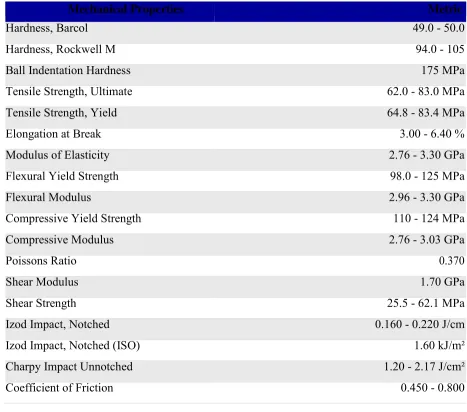
Table 2 Mechanical Properties of Acrylic
Mechanical Properties Metric
Hardness, Barcol 49.0 - 50.0
Hardness, Rockwell M 94.0 - 105
Ball Indentation Hardness 175 MPa
Tensile Strength, Ultimate 62.0 - 83.0 MPa
Tensile Strength, Yield 64.8 - 83.4 MPa
Elongation at Break 3.00 - 6.40 %
Modulus of Elasticity 2.76 - 3.30 GPa
Flexural Yield Strength 98.0 - 125 MPa
Flexural Modulus 2.96 - 3.30 GPa
Compressive Yield Strength 110 - 124 MPa
Compressive Modulus 2.76 - 3.03 GPa
Poissons Ratio 0.370
Shear Modulus 1.70 GPa
Shear Strength 25.5 - 62.1 MPa
Izod Impact, Notched 0.160 - 0.220 J/cm
Izod Impact, Notched (ISO) 1.60 kJ/m²
Charpy Impact Unnotched 1.20 - 2.17 J/cm²
9
[image:23.596.64.544.323.621.2]Table 3 Electrical Properties of Acrylic
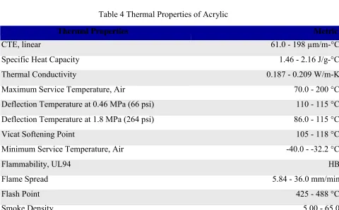
Table 4 Thermal Properties of Acrylic
Thermal Properties Metric
CTE, linear 61.0 - 198 µm/m-°C
Specific Heat Capacity 1.46 - 2.16 J/g-°C
Thermal Conductivity 0.187 - 0.209 W/m-K
Maximum Service Temperature, Air 70.0 - 200 °C
Deflection Temperature at 0.46 MPa (66 psi) 110 - 115 °C Deflection Temperature at 1.8 MPa (264 psi) 86.0 - 115 °C
Vicat Softening Point 105 - 118 °C
Minimum Service Temperature, Air -40.0 - -32.2 °C
Flammability, UL94 HB
Flame Spread 5.84 - 36.0 mm/min
Flash Point 425 - 488 °C
Smoke Density 5.00 - 65.0
Metric
Electrical Properties
Electrical Resistivity 1.00e+15 - 1.60e+16 ohm-cm
Surface Resistance 5.00e+13 - 1.90e+15 ohm
Dielectric Constant 2.70 - 4.00
Dielectric Strength 17.0 - 30.0 kV/mm
Dissipation Factor 0.0200 - 0.0600
10
CHAPTER 3
METHODOLOGY
3.1INTRODUCTION OF METHODOLOGY
This chapter describes the methodology used in this project to design and analyses the body of autonomous underwater vehicle. The flow chart shows the process stage. This project starts by studying the best way to obtain the best design preparation and to compare it with the existing design. By obtaining the best design, it can be a good result in experiment testing and to prove the efficiency compared to an existing design.
3.2GENERAL PROCESS