City, University of London Institutional Repository
Citation
:
Davenport, J. J., Hickey, M., Phillips, J. P. & Kyriacou, P. A. (2016). Method for
producing angled optical fiber tips in the laboratory. Optical Engineering, 55(2), 026120. doi:
10.1117/1.OE.55.2.026120
This is the draft version of the paper.
This version of the publication may differ from the final published
version.
Permanent repository link:
http://openaccess.city.ac.uk/13610/
Link to published version
:
http://dx.doi.org/10.1117/1.OE.55.2.026120
Copyright and reuse:
City Research Online aims to make research
outputs of City, University of London available to a wider audience.
Copyright and Moral Rights remain with the author(s) and/or copyright
holders. URLs from City Research Online may be freely distributed and
linked to.
City Research Online:
http://openaccess.city.ac.uk/
[email protected]
Method for producing angled optical fiber tips in
the laboratory
John J. Davenport,*Michelle Hickey, Justin P. Phillips, and Panicos A. Kyriacou
City University London, Research Centre for Biomedical Engineering, School of Computer Science, Mathematics and Engineering, Northampton Square, London EC1V 0HB, United Kingdom
1 Introduction
In recent years, optical fibers have become an extremely valuable industrial technology, most notably in telecommu-nications and also in sensors1–4 and a range of medical applications.5–7Specifically for sensors, fibers have the ad-vantage of being small in size and flexible, allowing them to reach remote locations. Their robustness and lack of require-ment for electrical power at the sensing site also allow them to find uses including monitoring conditions in coal mines2 and nuclear power stations8to medical blood gas sensing,9,10 optical coherence tomography,10and laser tissue ablation.7
Traditionally, optical fiber sensors use flat tips, cleaved and polished at 90 deg to the axis of the fiber.2,3,5,10 Light
leaves the tip and spreads out symmetrically about the axis of the fiber. However, by cleaving and polishing the tip at an angle, light can be directed to one side.10 The angle of the fiber can be used to vary the angle of output light and to control whether diffraction or reflection is dominant.5,11,12 This allows for sensing away from the axis of the fiber or for increasing coupling efficiency between a transmission and a return signal fiber.5 Angled tips give a greater degree of control at the sensing site.
Another use for angled fiber tips is laser-assisted surgery. The output of a high-power laser is guided along the optical fiber to the area of treatment such as a cancer tumor or a dental cavity.7 Laser energy can be used to ablate tissue, removing the need for invasive surgery. Angled tips can be used to direct laser light to the side of the fiber, allowing better control of the area to be ablated, and to reach areas otherwise difficult to get to.
There are several methods for producing angled fiber tips. They can be hand cleaved using a ruby-bladed fiber scribe or
similar tool, giving a high degree of flexibility but limited accuracy and repeatability. Laser cleaving offers a high level of precision,13 but the systems required to do so are
complex and expensive.
The third option is hand polishing, where the optical fiber is held in a mount and polished with increasingly fine lap-ping film. This method is common for flat tipped fibers, and mounts for holding fibers at 90 deg to the lapping film are widely available. Mounts at other angles are also available, but not at a wide range of angles. Mounts can be manufac-tured in the laboratory but require a material hard enough not to be significantly abraded by the lapping paper, which can be difficult to drill through at precise angle. This is especially for angles that deviate significantly from the perpendicular. Here, we present simple method for constructing and using mounts for polishing optical fiber tips to desired angles in the laboratory. The mount combines a hard polymer material for precise angled drilling with a thin metal plate to resist abrasion from the lapping paper. A single mount allows fibers to be polished at an angle set during construc-tion, with further mounts constructed if multiple angles are desired.
The novelty of the method is the construction and appli-cation of the mount, allowing control of tip angle to be added to the established method of fiber polishing. The combina-tion of the two materials allows the resulting angled fiber tip to be precisely controlled with the more malleable polymer, while also gaining the abrasion-resistant benefits of the harder metal plate. This allows the mount to be constructed with tools commonly available in a laboratory or technical workshop. The design of the construction and process allows for angled optical fiber tips to be constructed“in-house”by research groups without reliance on external constraints.
*Address all correspondence to: John J. Davenport, E-mail:john.davenport.1@
city.ac.uk 0091-3286/2016/$25.00 © 2016 SPIE
Keywords: angled-tip fiber probe; cleaving; optical fiber dispersion; optical fiber sensors; biomedical; photonics.
This paper explains how the mount was constructed, how it was used, and gives the results of some tests of the dispersion of LED light emitted from the tip of the fiber. The results from a flat-tipped optical fiber are included for comparison.
2 Theory
When an optical fiber is terminated with a flat, 90-deg cleave, light diffracts out in accordance with Snell’s law:
EQ-TARGET;temp:intralink-;e001;63;652
n1 sinθi ¼n2 sin θt; (1)
wheren1is the refractive index of the core,θiis the angle of light in the core to the boundary normal,n2is the refractive index of air or other medium surrounding the fiber, andθtis the angle of transmitted light exiting the fiber.
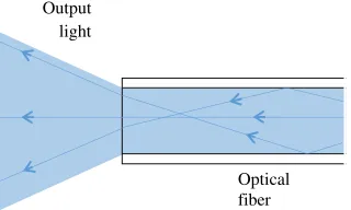
Figure1shows a diagram of light leaving the tip of a mul-timode optical fiber. It forms a conical shape as light from different modes diffracts at the boundary and spreads out. The angle of light spreading out from the fiber tip is the same as acceptance for incoming light to be transmitted through the fiber. This is referred to as the numerical aperture and is defined by the critical angle for total internal reflection between the core and the cladding and by the boundary con-ditions at the fiber tip.
Light traveling along the core of an optical fiber with an angled tip behaves in much the same way. However, when it reaches the end, the angle of the tip changes the diffraction pattern as the angle to the boundary normal of a given mode will be changed. For example, a mode traveling parallel to the optical fiber will diffract away from the normal and be diverted toward the angle of the tip.
Other modes are also diverted in accordance with Snell’s law [Eq. (1)]. Figure2shows a diagram of light diffracting from the tip of an angled fiber. The general effect is to impose an angular shift on the cone of light leaving the fiber as given by Eq. (2), derived from Snell’s law:
EQ-TARGET;temp:intralink-;e002;63;346
θshift¼sin−1
n1 n2 sinψ
−ψ; (2)
whereθshift is the angular shift on the cone of light leaving the fiber,no is the refractive index of the environment (air, water, and so on) andψ is the angle of the fiber tip.
The second effect of an angled fiber tip is side reflections, which is shown in Fig.3. When light reaches the end of an optical fiber, the majority is refracted out but a small portion
is reflected back. Usually this light travels back along the fiber but when the fiber tip is angled, it reflects laterally and can diffract out through the side of the fiber.11
The reflectivity at the boundary is given by the Franell equation for reflectivity:
EQ-TARGET;temp:intralink-;e003;326;529
R¼RsþRp
2 ¼
n1 cosθi−n2 cosθt n1 cosθiþn2 cosθt
2
þn1n1 cosθt−n2 cosθi cosθtþn2 cosθi
2∕2; (3)
where Ris the total reflectivity at the boundary, Rs is the perpendicular polarized component of reflectivity, Rp is the parallel polarized component of reflectivity, and other variables have the meanings given for Eq. (1).
3 Method
The following method was used to achieve angled fiber tips. The method was adapted from techniques for polishing perpendicular fiber tips with a polishing plate, which is a common and well understood technique.
3.1 Preparing the Fiber
The optical fiber used for this study was a600-μmdiameter core step-index multimode fiber (BFL48-600, Thorlabs, Newton, New Jersey). Table1gives a summary of the char-acteristics of the optical fiber.
The distal tip of the optical fiber was cleaved and cleaned. Using a manual cleaver at approximately the desired angle can save time grinding the surface. Alternatively, a fine-grain
Optical fiber Output
light
Fig. 1 Diagram of light leaving the tip standard multimode optical
fiber. It disperses out in a cone dependent on the angles of light rays within the core. The angle of divergence of the cone gives the numerical aperture.
shift
Optical fiber Output
light
Fig. 2 Diagram of light diffracting from the tip of the angled fiber. Light
diffracts away from the normal, imposing aθshiftshift on the exiting light cone.
Optical fiber Diffraction
Reflection
Fig. 3Diagram of light reflecting from the side of the angled optical
[image:3.630.366.526.58.166.2] [image:3.630.328.504.294.349.2] [image:3.630.105.265.609.705.2] [image:3.630.365.527.611.716.2]needle file could be used to approximate the desired angle. Accurate angle or keeping surface quality was unnecessary; however at this stage, a lot of material still needed to be removed.
3.2 Mounting the Fiber
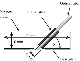
Figure4shows a diagram of the mount that was constructed for polishing angled fiber tips. The main part of the mount was a Perspex block through which an angled hole drilled through at angleα, the desired fiber tip angle. An aluminum base plate was attached to the underside with a hole drilled through it. The base plate provided a hard surface to the underside of the mount while the Perspex was easier to drill the angled hole through.
The fiber was given a plastic sheath to fit it tightly into the mount. We found that carefully wrapping it around with elec-trical tape to the desired radius worked. The sheathed fiber was then placed into the mount and securely attached to it (using soluble glue or more electrical tape). It was important that the fiber tip protruded slightly below the base plate and it could not easily rotate or slip position. A 4-mm diameter for the hole with an equivalent sheath was found to hold the fiber securely. Following these measurements exactly is not thought to be necessary to replicate the function of the method.
The angle of the fiber tip can be varied by varying the angle ψ of the hole drilled through the mount. A single mount can only deliver a single tip angle, but additional mounts can be made for further angles if desired. In each case, the hole should be centered on the center of the base plate on the lower side of the mount to allow the tip of the optical fiber to remain in the center of the base plate. The feasible range of angles achievable by this method is dependent on the dimensions and construction of the mount-ing block, as it is necessary to have a hole long enough sup-port the fiber during polishing. Another factor to consider is that a fiber tip is polished to a sharp angle, i.e., a large value ofψis at increasing risk of damage to the narrowest point of the tip as the“wedge”-shaped end, because it is increasingly delicate. The setup used here was found to be effective for producing tip angles between 0 deg and 45 deg. The error on tip angle produced was estimated to be0.5 deg, based on the accuracy of hole drilled through the mount.
3.3 Initial Polishing
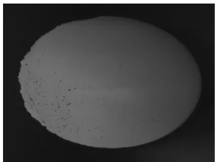
This was the most time-consuming step. Using coarse dia-mond lapping film (5-μm grit, Thorlabs), the surface of the fiber tip was smoothed to align with the angle of the mounting block. Figure-of-eight motions were used to ensure an even finish. Care was taken to avoid chips or cracks in the fiber surface, which was checked regularly with a microscope. Figure5 shows a microscope image of the angled fiber tip after polishing with 5-μmgrit lapping film.
3.4 Further Polishing
[image:4.630.62.303.76.228.2]After the initial polishing, increasingly fine diamond lapping film was used to achieve a smooth surface finish (3-, 1-, and 0.3-μm grit, all from Thorlabs). Again, figure-of-eight motions were used to ensure an even finish, and the surface was checked regularly with a microscope. The angled fiber mount tended to scuff the lapping film more than standard polishing disks, so it was important to avoid scuffed areas. Figure6shows a microscope image of the angled fiber tip after polishing with 3-, 1-, and 0.3-μm grit lapping film. Figure 7 shows a microscope image of side of the fiber tip, showing the 45-deg angle.
Table 1 Summary of characteristics of optical fiber.14
Characteristic Value
Transmission region 400 to 2200 nm
Core diameter 600μm2%
Cladding diameter 630μm2%
Coating diameter 1040μm5%
Core material Pure silica
Cladding material Polymer
Numerical aperture 0.480.02
Perspex
block
Base plate
40 mm
10 mm
Optical fiber
Plastic sheath
Fig. 4 Diagram of the mount used for polishing angled fiber tips. It
consists of a Perspex block through which a hole is drilled at angle
ψ. The optical fiber is held in place by the plastic sheath. The metal base plate is resistant to abrasion by the lapping paper.
Fig. 5Microscope image of the angled fiber tip after polishing with
[image:4.630.346.547.573.726.2] [image:4.630.102.266.579.705.2]3.5 Evaluation of Optical Properties
The refraction pattern of light leaving the angled optical fiber was found by launching light from a 470-nm (blue) LED (151033BS03000 Wurth Elektronik, Niedernhall, Germany) into the proximal end. Table2 gives a summary of the characteristics of the LED.
Light leaving the distal end with the angled cleave was allowed to fall incident onto screens placed in front
of and to the side of the fiber end to allow the refraction pattern to be observed. White 0.3-μm grit lapping film was used for screens as the fine grit surface prevented any coherent reflections. Figure 8 shows a diagram of the setup.
4 Results
Light emitted from the angled fiber end is dispersed into two regions. The first was refracted out through the angled sur-face. As explained in Sec. 2, this light followed a conical dispersion pattern shifted from the fiber axis by a significant angle. The second set of output light was reflected off the angled surface of the fiber and then refracted out through the side. Figure9shows the photographs of the light patterns from the front and side screens for a 45-deg tip. The front screen light pattern forms a similar optical fiber with a 90-deg surface cleave for comparison.
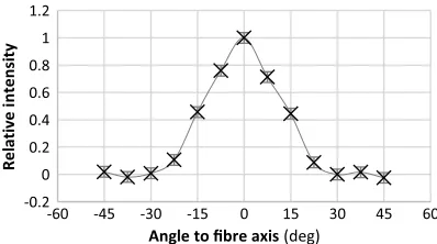
Next, the output intensity of the angled and the flat tipped optical fibers was measured at a range of positions. A power meter (3A-FS high-sensitivity thermal laser sensor, Ophir Photonics, Jerusalem, Israel) was placed 120 mm from the distal tip of each optical fiber and moved around to measure the intensity at a range of angles. Intensity values were measured relative to a dark baseline recorded prior to the experiment, so some low intensity figures were read as negative. The results are shown in Figs.10 and11.
Figure 10 shows the variation of output intensity with angle for flat tipped optical fiber. The output is concentrated symmetrically around the axis of the optical fiber. This is as it would be expected, as light travels through the optical fiber at a range of angles, diffracting out of the tip in a coni-cal shape.
Figure 11 shows the variation of output intensity with angle for the angle-tipped optical fiber. Here, we see that the central peak has shifted away from the fiber axis by approximately 30 deg. Using Eq. (2) and the fiber tip angle 45 deg gives a refractive index for the core material of approximately 1.4. This is close to the expected refractive index for pure silica at 470 nm of 1.46.16
Figure11also shows a second intensity peak centered at 90 deg. This is the light reflecting from the tip surface and diffracting out through the side of the optical fiber. As expected, 90 deg is twice the tip angle 45 deg. The intensity of the two peaks is dependent on the angle of incidence with
Fig. 6 Microscope image of the angled fiber tip after polishing with 3-,
1-, and0.3-μm grit lapping films (100×magnification).
Fig. 7 Microscope image of the side of the polished fiber tip showing
[image:5.630.75.288.57.217.2]the 40-deg angle (50×magnification).
Table 2 Summary of characteristics of the blue LED.15
Characteristic Value
Dominant wavelength 470 nm
Spectral bandwidth 20 nm
Package type 33 m (T-1)
Luminous intensity 3800 mcd
Viewing angle 30 deg
Diffracted
light
Reflected light LED
Optical fiber
Screens
Fig. 8 Diagram of the setup used to observe the refraction pattern
[image:5.630.342.550.59.178.2] [image:5.630.76.289.270.427.2] [image:5.630.62.303.633.748.2]the surface, as given in Eq. (3). The fibers used here have a numerical aperture of 0.48, giving aθiranging from 25.8 deg to 64.2 deg, relative to the tip face normal. By Eq. (3), this gives a reflectivity ranging from 4.0% at 25.8 deg to 100% (total internal reflection) above 43.2 deg and an average reflectivity across all angles of 58%. In some cases, it is pos-sible to select a tip angle for which the majority of light will be within the critical angle for total internal reflection, sig-nificantly increasing the proportion of light reflected out of the side of the fiber.5
5 Conclusion
Here, we present a method for producing and polishing opti-cal fibers with angled tips in the laboratory. The method used a mount made from a Perspex block through which a hole was drilled at the desired angle. An aluminum base plate attacked to the underside provided a hard surface against the lapping film. The optical fiber was set inside the mount. Surface quality was similar to what can be achieved with standard polishing disks.
(a) (b)
(c)
30 mm 30 mm
30 mm
Fig. 9 Photographs of the light patterns from the optical fibers: (a) diffracted light from the front of the
[image:6.630.135.492.59.381.2]45-deg angle-tipped optical fiber, (b) reflected light from the side of the 45-deg angle-tipped optical fiber, and (c) diffracted light from the front of the 90-deg flat-tipped fiber.
Fig. 10 Graph of the variation of output intensity with angle for
[image:6.630.339.551.449.564.2]flat-tipped optical fiber. Intensity is centered on the axis of the fiber. Errors come from the limit of sensitivity of the power meter. The res-olution of these relative intensity measurements was 0.04.
Fig. 11Graph of the variation of output intensity with angle for the
[image:6.630.83.282.450.561.2]The intensity of output light was measured at a range of angles. There were two peaks, one from the front face of the optical fiber, diffracted away from the angle of the tip. The second came from light reflected off the tip and diffracted out through the side of the fiber. The emission angle and relative intensity of both are dependent on the tip angle, allowing them to be controlled to suit the required application.
This study demonstrates the effectiveness of the method for producing optical fiber tips at desired angles. The method is simple to perform, based on well-established methods for optical fiber cleaving and polishing, and does not require advanced manufacturing tools. While it can be time consum-ing, the method is suitable for producing small quantities of angle-tipped optical fibers for research applications.
Acknowledgments
This report was independent research funded by the National Institute for Health Research [Invention for Innovation (i4i) program, Development of a multiparameter esophageal sensor for the early detection of Multiple Organ Dysfunction Syndrome (MODS), II-LA-0313-20006]. The views expressed in this publication are those of the author(s) and not necessarily those of the NHS, the National Institute for Health Research or the Department of Health.
References
1. S. K. T. Grattan et al.,“Monitoring of corrosion in structural reinforc-ing bars: performance comparison usreinforc-ing in situ fiber-optic and electric wire strain gauge systems,”IEEE Sens. J.9(11), 1494–1502 (2009).
2. Y. Zhao et al.,“Application in coal mine of fiber methane monitoring system based on spectrum absorption,”Procedia Eng.26, 2152–2156 (2011).
3. R. Chen et al.,“A cylindrical-core fiber-optic oxygen sensor based on fluorescence quenching of a platinum complex immobilized in a polymer matrix,”IEEE Sens. J.12(1), 71–75 (2012).
4. O. Oter, K. Ertekin, and S. Derinkuyu,“Ratiometric sensing ofCO2in
ionic liquid modified ethyl cellulose matrix,”Talanta76(3), 557–563 (2008).
5. G. Keiser et al.,“Review of diverse optical fibers used in biomedical research and clinical practice,”J. Biomed. Opt.19(8), 080902 (2014). 6. R. A. McCahon and D. K. Whynes,“Cost comparison of re-usable and single-use fibrescopes in a large English teaching hospital,” Anaesthesia70(6), 699–706 (2015).
7. C. Kim et al.,“Comparison of laser-assisted damage in soft tissue using bi-directional and forward-firing optical fiber,” Opt. Laser Technol.56, 196–206 (2014).
8. O. V. Butov et al.,“Fibers and sensors for monitoring nuclear power plants operation,”Proc. SPIE9157, 91570X (2014).
9. J. Jiang et al.,“Development of fiber optic fluorescence oxygen sensor in both in vitro and in vivo systems,” Respir. Physiol. Neurobiol.
161(2), 160–166 (2008).
10. H. Li et al.,“Feasibility of interstitial Doppler optical coherence tomography for in vivo detection of microvascular changes during photodynamic therapy,”Lasers Surg. Med.38(8), 754–761 (2006). 11. A. Sakamoto and T. Saito,“Computational analysis of responses of
a wedge-shaped-tip optical fiber probe in bubble measurement,” Rev. Sci. Instrum.83(7), 075107 (2012).
12. S. W. Kim,“High-temperature fiber optic sensor using a grating on an angled fiber tip,”Jpn. J. Appl. Phys.41(3A), 1431–1435 (2002). 13. G. V. Steenberge et al.,“Laser cleaving of glass fibers and glass fiber
arrays,”J. Lightwave Technol.23(2), 609–614 (2005).
14. Thorlabs, Inc.,“0.48 NA polymer clad multimode fiber,”Technical Data Sheet, Report No: 12253—S01, ref F, Thorlabs, Inc., Newton, New Jersey (2015).
15. Wurth Elektronik,“151033BS03000 WL-TMRW THT LED round clear blue,” Technical Data Sheet, Wurth Elektronik, Niedernhall, Germany (2015).
16. I. H. Halitson,“Interspecimen comparison of the refractive index of fused silica,”J. Opt. Soc. Am.55(10), 1205–1209 (1965).
John J. Davenportis an early career researcher, holding an MSc
degree in physics and an MSc degree in photonics from Imperial College London and a PhD in engineering photonics from Cranfield University. He currently holds a research associate position in biomedical engineering at City University London. His research to date focuses on spectroscopic detection and analysis of gases in complex environments such as industrial buildings or the human body, specifically on sensitivity and specificity optimization.
Michelle Hickeyis a researcher at City University London. Her work
includes the development of biomedical optical sensors, design of medical electronics and instrumentation, and conducting physiologi-cal measurement studies. Her research interests involve applying monitoring techniques to extract new variables for the assessment of cardiovascular health.
Justin P. Phillipsresearches biomedical optical sensors and
instru-mentation applied to vital signs monitoring of critically ill patients dur-ing surgery and in intensive care. This work also extends to the development of new technologies for screening patients for life threat-ening conditions such as anemia and diabetes as well as providing solutions for patients to monitor their own conditions at home. He cur-rently holds a Royal Academy of Engineering/Leverhulme Trust Senior Research Fellowship.
Panicos A. Kyriacouis a professor of biomedical engineering, an