DESIGN OF A COMPOSITE ARITHMETIC UNIT FOR RATIONAL NUMBERS
Tomasz Pinkiewicz, Neville Holmes, and Tariq Jamil
School of Computing University of Tasmania Launceston, Tasmania 7250
AUSTRALIA
Abstract: As we advance into the new century, computers of the future will require techniques for arithmetic operations that take advantage of the modern technology and yield accurate results. Floating-point arithmetic has been in use for nearly forty years but is plagued with inaccuracies and limitations which necessitates introduction of a new concept in computer arithmetic called composite arithmetic. This paper describes composite arithmetic and design of an arithmetic unit based on this concept.
Keywords: computer arithmetic, floating-point arithmetic, composite arithmetic, arithmetic unit, rational numbers.
1. Introduction
Fixed-point arithmetic was first used after World War Two to perform calculations on integer values and to represent them exactly. A programmer had several lengths of representation to cope with expected range of numbers. In integer arithmetic, calculation of fractions was done using scaling and this could produce inexact results [1,2]. Scaling required problems to be pre-processed by the user and then they could be accommodated by fixed point-representation. However, with increasing speed of computers, more complex operations had to be performed and the pre-processing became a lengthy process [3]. Also large numbers introduced a new concept in computer arithmetic called overflow. To overcome this problem, floating-point arithmetic was introduced.
Floating-point arithmetic can cope with large range of number but it does so only by approximating. The numbers are represented in semi-logarithmic form and they have two components, significand and exponent. The significand expresses the precision of the number while the exponent expresses the range of the values that can be represented. This floating-point representation became a standard and is used in all older and modern computers. However, this notation has many problems, which have been accepted (or ignored) over the years.
Results of floating-point arithmetic can vary. They can be satisfactory, inaccurate, or completely
wrong. However there is no way of telling which one of them has occurred. Although much larger range of values can be stored, comparing to fixed-point form, there is still problem of overflow. Additional to the overflow, floating-point introduces underflow, where the number is too small to be represented accurately. Different lengths of representation mean that a compromise between precision and the storage space has to be made. This can then affect accuracy of the arithmetic. Accuracy is also affected by truncating and rounding errors, and by conversion of values to and from the display form. Another problem with floating-point arithmetic is that it doesn’t consider special values. These are zero, infinity, and indeterminacy. These are still results and can be very important in scientific calculations. Kulisch [4] describes five equations, all of them containing the same numbers with the same signs, but arranged differently. Conventional computer with floating-point standard returns different values for each equation, while they should all be the same. Several other examples are provided which prove that even simple mathematical equations can be miscalculated when using floating-point form.
Another type of problem is concerned with programming issues. The programmer has to determine beforehand if fixed-point or floating-point notation should be used and what kind of precision is desired (single or double). Then there is a problem of handling exceptions, and problem of converting between different forms and how this affects accuracy of the result. Another concern is the accuracy of the display and how exceptions and special values will be displayed. All this has to be considered by the programmer and wrong decision can cause erroneous results.
Floating-point representation is an improvement over fixed-point form. However, today’s computers have become faster and have to perform more accurate and larger calculations. Current technology and requirements make the floating-point form “obsolete” and a new type of computer arithmetic is needed. One of the examples of advanced computer arithmetic is scalar product concept presented by Kulisch [4].
operations on exact forms. Section 2 introduces concepts of composite arithmetic and section 3 describes design of the Composite Arithmetic Unit. Finally, conclusion is presented in Section 4 followed by a list of references.
2. Composite Arithmetic
Composite Arithmetic [1] is based on advanced computer arithmetic concept and combines several different formats. These are stored in a single binary form and the formats are distinguished using tags. The storage form is specified by multiples of 16 and four lengths are recommended: short (32 bits), normal (64 bits), long (128 bits) and extended (256 bits). For most commercial calculations on exact numbers and scientific computations on inexact numbers, 32- and 64-bit sizes would be sufficient. The long and extended formats (128- and 256-bit) can be used for financial and number theory calculations where very long exact results can occur. Also some intermittent technical computations where very precise results are needed would use one of these two formats. Composite arithmetic merges both exact and inexact formats using a tag bit. The bit is set to 0, if the number is exact and it is set to 1, if it is inexact.
For exact values there are two forms (Figure 1). The primary one is an integer form and secondary is rational form. To distinguish between them another bit is added to the tag field. In the integer form all bits, except the tag, can be used to store the value. Negative numbers are stored using 2s complement of the magnitude. This ensures that zero is stored exactly and prevents negative zero. Rational numbers are typically result of integer division. They can be stored exactly as integers if proper representation is adopted. The secondary exact form allows storing very large numbers, or very small numbers, depending on the size of numerator and denominator. To allow this, the form must provide for sharing of the value bits between numerator and denominator. The solution to that is called a floating slash and it is several bits, depending on word length that separate the numerator from the denominator. For example, for a 32-bit number, five bits are needed to be stored to accommodate the floating slash. If the numerator is 1 then all bits are available for the denominator. If the denominator is 1 then the number will be stored in an integer format; therefore the smallest denominator is 2. There are other issues, which have to be addressed when using this form. First, the denominator can be 0, which means that the number is infinity. Infinity needs storing because it can result from division by zero. Moreover indeterminate result needs storing as well.
If the value cannot be stored exactly then the composite arithmetic will store it in an inexact form. Numbers can be represented in different ways. The first
one is called double-number form. An example of it is the floating-point representation. The second one is called single-number form and an example of it is relatively new, signed logarithmic form. This form is subdivided into primary inexact and secondary inexact forms. Primary form uses signed pure logarithmic representation and secondary form uses antitetrational representation. This second form has been adopted by the Composite Arithmetic.
While the above forms are satisfiable for storage purposes, they are not suitable for display. This is because to display, numbers are represented as characters and their values have to be converted to and from an appropriate storage form. Deficiency of the ASCII character set puts several restrictions on available choices. A form for exact values uses decimal point and a fraction point. This would allow a number 456 ¾ to be represented as 456.3.4, where first dot is a decimal point and second dot is a fraction point. A number ½ would be stored as 0.1.2. This approach would also allow displaying infinity as 0.1.0 and indeterminacy as 0.0.0. Representation of inexact numbers would be similar to the e-notation, where the exponent uses scaling base of 10. The display form would use the scaling base of 1000 and this would be called k-notation. This will be supported by m-notation (milli notation) to avoid squeezing a negative sign into the exponent. A second k
or m could display secondary inexactness.
The Composite Arithmetic proposal also mentions register form. This would be a fixed-point long accumulator, which is be 512 bytes (4096 bits) long. It would be large enough to store extended primary inexact storage form and some additional data like tags and signs.
Composite arithmetic is more complex than floating-point but many aspects of it have already been implemented in hardware and software. Replacing floating-point arithmetic would benefit electronic calculator arithmetic and would improve capabilities of software packages such as spreadsheets. Another advantage lies in programming using the composite arithmetic. The programmer wouldn’t have to make choices between fixed and floating point and all conversions would be done in the register form. Also the accuracy of results, especially for technical computation, would be much greater.
3. Design of the Composite Arithmetic Unit
Figure 1. Proposed exact storage forms include (a) primary exact form (integer), and (b) secondary exact form (rational). In the bit numbering as shown, n stands for the number of bits in the form and can be 32, 64, 128, or 256, while m stands for
the number of different forms in increasing size of 0,1,2, or 3.
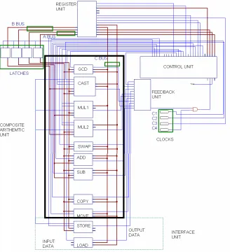
Figure 2. Composite Arithmetic Unit (enclosed in rectangle) as part of a larger design.
The design involves a Composite Arithmetic Unit (CAU), a set of registers and control unit to allow interfacing with the PC. The CAU consists of six basic blocks (Figure 2): greatest common divisor (GCD), casting (CAST), multiplication (MUL1 for numerator
[image:3.570.132.460.264.624.2]3.1 GCD block
The function of this circuit is to calculate the greatest common divisor of numerator and denominator of a rational number. The outcome of this operation is a number, which can be used with the rational number to cast out the common factors and reduce the size of the number.
The algorithm for finding GCD is based on the Euclid’s Algorithm. There are several variations of the Euclid’s Algorithm (including binary algorithm used in computing) but the following algorithm is a simple recursive function and can be easily implemented using hardware components.
int gcd(int m, int n) // m is numerator,
// n is denominator
{
if (m < n) // when numerator is // greater than denominator
{
m = gcd (m, n - m); // make a recursive call // with adjusted denominator
return m; }
else if (m > n) // when numerator is less //than denominator
{
m = gcd (m - n, n); // make a recursive // call with adjusted // numerator
return m; } else
return m; // When numerator equals // denominator
// Stop and return the numerator (m), // Which holds the GCD of (m,n)
}
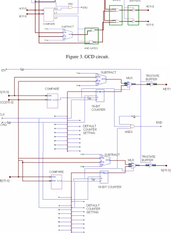
The GCD circuit (Figure 3) consists of two input data buses: A [15:0] (denominator) and B [15:0] (numerator). The EN line enables the outputs and is used to generate the END signal. The output data buses are M [15:0] (denominator) and N [15:0] (numerator). The END line signals the end of operation and the result is contained in M bus. COMPARE unit checks if the two input buses are equal, A bus is less than B bus, or A bus is greater than B bus. If A bus equals B bus then EQ line goes high. It is then ended with EN line to set the line END to high. If A bus is less than B bus (LT line is high) then AND gates for the upper SUBTRACT unit are enabled. If A bus is greater than B bus (GT line is high) then AND gates for the lower SUBTRACT unit are enabled. Both outputs from the AND gates are put
through OR gates and the final output is M and N buses, regulated using TRISTATE BUFFERS.
3.2 CAST block
Casting circuit is used to eliminate the common factors of two numbers. The GCD value previously stored in a register is fetched into the casting circuit. Casting out common factors allows decreasing the size of the numerator and denominator while still maintaining the precision.
The algorithm for casting out common factor uses simple subtraction of GCD from numerator and denominator until they reach 0. The number of subtractions for each number produces the new numerator and denominator. This is equivalent to dividing the rational number by the GCD.
void cast(int& m, int& n, int gcd) // m is the numerator, //n is the denominator
{
int count1=0; // counts subtractions of the numerator
int count2=0; // counts subtraction of the // denominator
while (m > 0) // while loop for the numerator
{
count1 = count1 + 1; // add one to the counter
m = m - gcd; // subtract the GCD from the // numerator
}
while (n > 0) // while loop for the denominator
{
count2 = count2 + 1; // add one to the counter
n = n - gcd; // subtract the GCD from the
// denominator
}
m = count1; // The new numerator is set to // the count of subtractions
n = count2; // The new denominator is set to // the count of subtractions
}
Figure 3. GCD circuit.
[image:5.570.119.468.166.641.2]provides feedback to the END line and it manipulates the MUX selector. SUBTRACT units subtract GCD bus from the A bus. The output of the SUBTRACT and the 16-BIT COUNTER are put through the MUX selector. If the COMPARE output line is low, then the SUBTRACT output goes through, and if it is high, then the 16-BIT COUNTER output goes through. The final output M [15:0] is put through the TRISTATE BUFFER. The B bus operates on the same principle and its output goes to N [15:0]. DEFAULT COUNTER SETTING lines are set to GND and VCC connections in order to initialise the counter (using LOAD line).
3.3 MUL1 and MUL2 blocks
These circuits, similar to one another, are used to multiply the numerators (MUL1) and denominators (MUL2) of the two rational numbers.
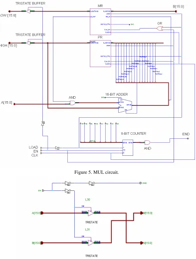
The design for these circuits is based on Hwang’s algorithm [3]. The MUL circuit (Figure 5) consists of two input buses: A [15:0] (multiplicand) and B [15:0] (multiplier). The input lines are LOAD (loads the counter), EN (enable line) and CLK (clock line). The output buses are LOW [15:0] (lower 16-bits of the result) and HIGH [15:0] (higher 16-bit of the result). There are three registers involved in the circuit. The first two are internal. These are MR (Multiplier Register) and PR (Partial product Register). The third register contains the Multiplicand (A bus) and it belongs to the Register Unit. Also 16-BIT ADDER is required to produce the partial product. The result of the multiplication is a 32-bit number, which is stored in LOW and HIGH buses, corresponding to 16 lower bits and 16 higher bits respectively. An 8-BIT COUNTER is used to keep track of the number of additions and to signal the completion of operation by setting the END line to high. For each clock cycle there are a number of operations that are carried out. First Multiplicand A is ANDed with LSB of MR. This result is added to the PR (initially zero). The 15 higher bits of the sum are put into 15 lower bits of the PR. The LSB of the sum is then right shifted into MR and becomes the MSB of the MR. The Cout from the ADDER is put into the MSB of the PR. The 8-BIT COUNTER controls the number of right shifts of the MR, so at the end of the multiply operation the MR contains 16 lower bit of the result. The Multiplier B that was originally in the MR is pushed towards the right end of the MR.
3.4 SWAP block
The swap circuit is used for swapping numerator and denominator to produce the reciprocal of the original number. Multiplication (MUL blocks) of a given number with the reciprocal of the second number (output from SWAP block) yields the result of dividing the first number with the second number.
The SWAP circuit (Figure 6) consists of two input data buses: A [15:0](denominator) and B [15:0](numerator). These are put through tristate buffers using EN line to activate the buffers. Then A bus is tied to N [15:0] (numerator) and B bus is tied to the M [15:0] (denominator). The final output line is END, which has been inverted twice to strengthen the signal.
3.5 ADD block
This circuit performs addition of numerators of two rational numbers. The denominators must be the same in order to produce the correct result.
The ADD circuit (Figure 7) consists of three data inputs: A [15:0], B [15:0] and LOW [15:0]. A and B buses are numerators of the numbers to be added, while LOW bus is the common denominator. The input line EN enables the whole circuit. The circuit works by adding A and B and sending the result to N [15:0] via TRISTATE buffer. The LOW bus goes through to the M [15:0] output bus and is enabled using TRISTATE buffer. The output line END has been inverted twice to strengthen the signal.
3.6 SUB block
The subtraction circuit performs subtraction of the numerators (denominators must be the same).
Figure 5. MUL circuit.
Figure 7. ADD circuit.
Figure 8. SUB circuit.
4. Conclusion
Composite Arithmetic offers great advantages over the current fixed-point and floating-point arithmetic. It is accurate and can deal with infinity and indeterminacy. The aim of this research has been to design a Composite Arithmetic Unit which will deal with all aspects of arithmetic (exact and inexact) automatically and without any user input. Future research will concentrate on developing inexact forms and then the integration of the two forms (exact and inexact) will follow. Once this is achieved, the final specification for the standard can be formulated. Then it will also be possible to design more complex operations dealing with wider range of calculations. Today’s technology and needs require a new type of arithmetic, and composite arithmetic may be the answer for the future central processing units, providing automatic conversion
between exact and inexact forms and freeing user from making hard decisions at programming level.
References
[1] N. Holmes, “Composite Arithmetic: Proposal for a New Standard”, IEEE Computer, Vol. 30, No. 3, pp. 65-73, March 1997.
[2] N. Holmes, “Floating Point and Composite Arithmetics”, published in Proceedings of 8th Biennial Computational Techniques and Applications Conference, Adelaide, South Australia, 1997.
[3] K. Hwang, Computer Arithmetic – Principles, Architecture, and Design, John Wiley & Sons, 1979. [4] U.W. Kulisch, “Advanced Arithmetic for the Digital Computer – Design of Arithmetic Units”, Version 2, 1999.