NEW TECHNIQUE FOR THE DEVELOPMENT OF OPEN CNC CELL CONTROLLER BASED ON ISO 14649 and ISO 6983
KAMRAN LATIF
A thesis submitted in
fulfillment of the requirement for the award of the Degree of Doctor of Philosophy in Mechanical Engineering
Faculty of Mechanical and Manufacturing Engineering Universiti Tun Hussein Onn Malaysia
v
ABSTRACT
vi
ABSTRAK
vii
TABLE OF CONTENTS
DECLARATION ii
DEDICATION iii
ACKNOWLEDGEMENT iv
ABSTRACT v
ABSTRAK vi
TABLE OF CONTENTS vii
LIST OF TABLES xii
LIST OF FIGURES xiii
LIST OF ABBREVIATIONS xvii
LIST OF APPENDICES xxii
LIST OF PUBLICATIONS cli
LIST OF AWARDS AND ACHIEVEMENTS xxiii
CHAPTER 1 INTRODUCTION 1
1.1 Research Background and Motivation 1
1.2 Problem Statement 4
1.3 Aim of the Study 5
1.4 Scope of the Study 5
1.5 Limitations of the Study 5
1.6 Objectives of the Study 6
1.7 Thesis Format 7
CHAPTER 2 LITERATURE REVIEW 8
2.1 Introduction 8
2.2 Computer Numerical Control 8
2.3 ISO 6983 10
2.4 ISO 10303 14
2.4.1 Antiquity of ISO 10303 14
viii
2.4.2.1 Description Methods 15
2.4.2.2 Implementation Methods 16
2.4.2.3 Conformance Testing 18
2.4.2.4 Integrated Resources 18
2.4.2.5 Application Protocols 19
2.4.3 Architecture of STEP 22
2.5 STEP-NC 24
2.5.1 Versions of STEP-NC 24
2.5.1.1 ISO 14649 24
2.5.1.2 ISO 10303-238 26
2.5.2 Benefits of STEP-NC 27
2.5.3 Structure of STEP-NC 30
2.5.4 STEP-NC Part 21 Physical File Representation 32
2.6 Implementation of STEP-NC on CNC 34
2.6.1 Major Projects 35
2.6.2 CNC Controller 36
2.6.2.1 Open Architecture Control Technology 36 2.6.2.2 Categories of Open Architecture Control
Solution 38
2.6.2.3 Major OAC International Projects 39 2.6.3 Next Generation CNC Controllers 46 2.6.3.1 Indirect STEP-NC Approach 47 2.6.3.2 Interpreted STEP-NC Approach 50
2.7 Research Gaps 68
2.8 Summary 81
CHAPTER 3 RESEARCH METHODOLOGY 82
3.1 Introduction 82
3.2 Methodology 82
3.3 Task 1 - Hardware Configuration 84
3.4 Task 2 - Software Configuration 86
3.5 Task 3 - Integration of Hardware and Software
Configurations 87
3.6 Task 4 - Validation of System 88
ix
3.8 Summary 89
CHAPTER 4 SYSTEM DEVELOPMENT 90
4.1 Introduction 90
4.2 System Architecture 90
4.3 ISO Data Interface Models Interpretation Module 91 4.3.1 Architecture of ISO Data Interface Models
Interpretations Module 92
4.3.1.1 Information Sub Module 92
4.3.1.2 Extraction Sub Module 93
4.3.1.3 Production Sub Module 94
4.3.2 Algorithm Design of ISO Data Interface Models
Interpretation Module 99
4.3.2.1 Algorithm Design for ISO 14649
Interpretation 99
4.3.2.2 Algorithm Design for ISO 6983
Interpretation 101
4.3.3 GUIs of ISO Data Interface Models
Interpretations Module 103
4.3.3.1 GUI for ISO 14649 Interpretation 103 4.3.3.2 GUI for ISO 6983 Interpretation 105
4.4 3D Simulation Module 107
4.4.1 Algorithm Design of 3D Simulation Module 109 4.4.2 GUI of 3D Simulation Module 109
4.5 Machine Motion Control Module 111
4.5.1 Hardware Configuration 111
4.5.2 Software Configuration 112
4.5.2.1 Encoder Connection and Calibration 113
4.5.2.2 DBC Mapping 115
4.5.2.3 DBC +1 116
4.5.2.4 DBC +Half 117
4.5.2.5 DBC Movement 118
4.5.2.6 DBC Home Sequence 121
4.5.2.7 DBC Move to Previous Position 122
x
4.5.2.9 DBC Manual Operate 124
4.5.3 Algorithm Design of Machine Motion Control
Module 127
4.5.4 GUI of Machine Motion Control Module 128
4.6 Live Video Monitoring Module 130
4.6.1 Algorithm Design of Live Video Monitoring
Module 131
4.6.2 GUI of Live Video Monitoring Module 132 4.7 Automatic Document Generation Module 133
4.7.1 Algorithm Design of Automatic Document
Generation Module 134
4.8 System Algorithm Design 136
4.9 Summary 138
CHAPTER 5 EXPERIMENTAL STUDY 139
5.1 Introduction 139
5.2 Experiments based on ISO 14649 Data Interface Model 139
5.2.1 Experiment 1 139
5.2.2 Experiment 2 141
5.3 Experiments based on ISO 6983 Data Interface Model 143
5.3.1 Experiment 1 143
5.3.2 Experiment 2 145
5.4 Summary 146
CHAPTER 6 CONCLUSION AND FUTURE RECOMMENDATIONS 147
6.1 Introduction 147
6.2 Conclusion 147
6.3 Contributions of the Study 148
6.3.1 Major Contributions 148
6.3.2 Minor Contributions 149
6.4 Summary 149
6.5 Future Works 150
REFERENCES 153
APPENDIX I 163
APPENDIX II 166
xi
APPENDIX IV 169
APPENDIX V 171
APPENDIX VI 174
APPENDIX VII 175
APPENDIX VIII 176
APPENDIX IX 177
APPENDIX X 179
APPENDIX XI 181
APPENDIX XII 183
APPENDIX XIII 185
APPENDIX XIV 186
APPENDIX XV 187
APPENDIX XVI 188
xii
LIST OF TABLES
2. 1 ISO 6983 advantages and disadvantages 13
2. 2 STEP standard parts 15
2. 3 List of Application Protocols 20
2. 4 Comparison between both versions of STEP-NC 27 2. 5 Comparison between STEP-NC and ISO 6983. 29 2. 6 Summary of some of the previous efforts on STEP-NC 58
2. 7 Summary of demonstrations 58
2. 8 Literature overview and comparison with proposed
system 71
3. 1 DENFORD NOVAMILL specification 84
xiii
LIST OF FIGURES
2. 1 ISO 6983 CNC coding 10
2. 2 ISO 6983 vendor dependency environment 12 2. 3 Current manufacturing system information flow 12 2. 4 Example of EXPRESS and EXPRESS-G schema 16 2. 5 Example of ISO 10303-21 physical file 17 2. 6 Example of ISO 10303-28 physical file (Lee et al.,
2006) 18
2. 7 STEP architecture approaches (Fowler, 1995) 23 2. 8 ISO 14649 design manufacturing life cycle 25
2. 9 Current CAx data flow 28
2. 10 STEP-NC CAx data flow 28
2. 11 Structure of STEP-NC data model (ISO, 2002a; Zhang
et al., 2013) 31
2. 12 EXAMPLE 1 part (ISO, 2002a) 32
2. 13 Structure of EXAMPLE 1 part program based on
part-21 implementation method 34
2. 14 Criteria of OAC (Pritschow et al., 2001) 38 2. 15 Different types of OAC solutions (Nacsa, 2001) 38 2. 16 Architecture of OSACA (Association, 2001) 40 2. 17 OSEC architecture (Pritschow et al., 2001) 41 2. 18 OMAC architecture (Pritschow et al., 2001) 42 2. 19 Demonstration of PAPI (Ueno et al., 2000) 43 2. 20 Common data and service modules for a global HMI
API 43
2. 21 OCEAN system architecture (Brecher et al., 2010) 44 2. 22 Popularity survey on OAC systems (Brecher et al.,
xiv 2. 23 Stages of STEP-NC evolution (Hamilton et al., 2014;
Rauch et al., 2012) 46
2. 24 STEP-Compliant CAD/CAPP/CAM/CNC scenario
(Consortium, 2003) 48
2. 25 Framework of AB-CAM system (Nassehi et al., 2006) 49 2. 26 Working principle of PosTECH STEP-NC (Lee et al.,
2006) 51
2. 27 System control configuration (Zhao et al., 2009) 51 2. 28 GUI and architecture of the system (Weck & Wolf,
2002) 52
2. 29 STEPturn process planning (Xu et al., 2005) 53
2. 30 Organisation of the system 53
2. 31 WEDM STEP-NC system 54
2. 32 Architecture of SPAIM (Hamilton et al., 2014) 55 2. 33 Overview of IIMP (Hamilton et al., 2014) 56 2. 34 Overview of XMIS (Hamilton et al., 2014) 56 2. 35 ITP platform (Hamilton et al., 2014) 57
2. 36 Criteria of STEP-CNC system 59
3. 1 Flowchart of research methodology 83
3. 2 Hardware configurations 85
3. 3 Software Configuration 86
3. 4 System Configuration 88
3. 5 Working principle of proposed system 89 4. 1 Internal structure of ISO data interface models
interpretation module 91
4. 2 Snapshots of the information sub module block
diagrams 92
4. 3 Functionality of extraction sub module 93 4. 4 Snapshots of the extraction sub module block diagrams 94 4. 5 Generated tool path for planar face and pocket process 97 4. 6 Generated tool path for drilling process 97 4. 7 Block diagrams pictures of tool path generator
xv 4. 8 Block diagrams images of output and physical file
generator functional modules 98
4. 9 Flow chart of ISO 14649 interpreter algorithm design 101 4. 10 Functionality of the ISO 14649 algorithm design 102 4. 11 ISO 6983 interpreter algorithm functionality 103
4. 12 GUI of ISO 14649 interpreter 104
4. 13 GUI of ISO 6983 interpreter 106
4. 14 Internal structure of 3D simulation module 107 4. 15 Block diagrams of 3D simulation module 108 4. 16 Flow chart of 3D simulation module algorithm design 110
4. 17 GUI of the 3D simulation module 111
4. 18 Hardware configuration of MMC module 112 4. 19 Internal structure of MMC module 113 4. 20 Block diagrams of encoder connection and calibration
sub module 115
4. 21 Block diagrams of the DBC home sub-module 116 4. 22 Block diagrams of DBC +1 sub module 117 4. 23 Working principle of DB +1 sub module 118 4. 24 Block diagrams of DBC movement sub module 119 4. 25 Working principle of DBC movement sub module 120 4. 26 Block diagrams of DBC home sequence sub module 121 4. 27 Block diagrams of DBC move to previous position sub
module 122
4. 28 Block diagrams of the functional modules of DBC
sequence sub module 123
4. 29 Working principle of DBC sequence sub module 125 4. 30 Block diagrams of move drill bit changer and drill bit
clamper manual control functions 126
4. 31 Block diagrams of set axis positions control function 126 4. 32 Block diagrams of tool change, teach tool mapping,
tool change half and jog +- control functions 127 4. 33 Flow chart of MMC module algorithm design 129
4. 34 GUI of MMC module 130
xvi 4. 36 Flow chart of LVM module algorithm design 132
4. 37 GUI of the LVM module 133
4. 38 Block diagrams of ADG module 134
4. 39 Flowchart of ADG module algorithm design 135 4. 40 Flow chart of developed system algorithm design 136 4. 41 System algorithm design in terms of GUIs 137 5. 1 Graphical view of experiment 1 processes 141
5. 2 Manufactured part 141
5. 3 Graphical view of experiment 2 processes 142
5. 4 Manufactured part 142
5. 5 Graphical representation of experiment 1 144
5. 6 Manufactured part 145
5. 7 Graphical representation of experiment 1 145
xvii
LIST OF ABBREVIATIONS
2.5D Two-and-a-half Dimensional
2D Two Dimensional
3D Three Dimensional
3DS Three Dimensional Simulation
AAM Application Activity Model
AB-CAM Agent Based Computer Aided Manufacturing
AD Analog to Digital
ADG Automatic Document Generator
AI Artificial Intelligent
AIM Application Interpreted Model
AM Application Module
AO Architecture Object
AP Application Protocol
API Application Program Interface
ARM Application Reference Model
ASC American Standard Code
ASIC Application Specific Integrated Circuit
ATC Automatic Tool Changer
CAA Component Application Architecture
CAD Computer Aided Design
CAM Computer Aided Manufacturing
CAPP Computer Aided Process Planning
CAx Computer Aided Systems
CC Conformance Classes
CCC or C3 Conical Code Converter
CE Compact Edition
xviii
CNC Computer Numerical Control
COM Component Object Model
CPU Central Processing Unit
DA Digital to Analog
DBC Drill Bit Changer
DH Drill Head
DIO Digital Input Output
DLL Dynamic Link Library
DNC Direct Numerical Control
DRC Distributed Reconfigurable Controller
DSP Digital Signal Processing
EMC Enhanced Machine Controller
ESPRIT European Strategic Program on Research in Information Technology
EtherCAT Ethernet for Control Automation Technology
EtherMAC Ethernet for Manufacturing Automation Technology
EU European Union
FBICS Feature Based Inspection and Control System FBMash Feature Based Machining
FBTol Feature Based Tolerancing
FDL Flowchart Description Language
FM&T Federal Manufacturing and Technologies
FMS Flexible Manufacturing System
FPGA Field Programmable Gate Array
FSMC-OA FoFdation Smart Machine Controller-Open Architecture GD&T Geometric Dimensioning and Tolerancing
GUI Graphical User Interface
HMI Human Machine Interface
I/O Input/Output
IDEF Integrated DEFinition for function modeling IEEE Institute of Electrical and Electrons Engineers IGES Initial Graphics Exchange Specification
IIMP Intelligent and Interoperable Manufacturing Platform
xix IMS Intelligent Manufacturing System
IMSCMI Intelligent Manufacture for STEP-NC Compliant Machining and Inspection
IP3AC Integrated Platform for Process Planning And Control IPC Intrinsically Passive Controller
IPIM Integrated Product Information Model ISO International Standards Organization
ITP Integrated Test Platform
JIS Japanese Industrial Standard
JOP Japanese Open Promotion group
LabVIEW Laboratory Virtual Instrument Engineering Workbench
LVM Live Video Monitoring
MADCON Multi Agent Distributed Controller
MATLAB MATrix LABoratory
MCC Motion Control Card
MDICM Model Driven Intelligent Control of Manufacturing
MFA Manufacturing Feature Agent
MIM Module Integrated Model
MMC Machine Motion Control
MMI Man Machine Interface
MPU Micro Processing Unit
NC Numerical Control
NCC NIST-SAI Conical Code
NCK Numeric Control Kernel
NI National Instruments
NIST National Institute of Standards and Technology
NN Neural Network
NRL-SNT National Research Laboratory for STEP-NC Technology
NT New Technology
NURBS Non Uniform Rational Basic-Spline
OAC Open Architecture Control
OCEAN Openness, Conscientiousness, Extroversion, Agreeableness and Neuroticism
xx ORCOS Organic Reconfigurable Operating System
OS Operating System
OSACA Open System Architecture for Controls within Automation Systems
OSEC Open System Environment for Controllers
OWL Ontology Web Language
PAPI Principal Application Programming Interface
PC Personal Computer
PCI Peripheral Component Interconnect PIC Peripheral Interface Controller
PLC Programmable Logic Control
PMAC Packet Media Access Controller
RAMP Rapid Acquisition of Manufactured Parts
RT Real Time
RTAI Real Time Artificial Intelligent
RTOS Real Time Operating System
SAI Stand Alone Interpreter
SC Sub Committee
SDAI STEP Data Access Interface
SERCANS Module of Master SERCOS interface-A product from Bosch Rexroth
SERCOS SErial Real-time COmmunication System
SFP Shop Floor Programming
SIM System for Interconnecting of Media
SMS STEP Manufacturing Suite
SPAIM STEP-NC Platform for Advance and Intelligent Manufacturing
STEP Standard for The Exchange of Product Data
STEPcNC STEP-compliant NC
STEP-NC Standard for The Exchange of Product Data-Numerical Control
TC Technical Committee
TPG Tool Path Generator
xxi
TTL Transistor Transistor Logic
UK United Kingdom
UMI Universal Motion Interface
UNL Universal Logic Network
USA United States of America
USB Universal Serial Bus
VB Visual Basic
VDAFS Verband der Automobilindustri Flachenschnittstelle VISA Virtual Instrument Software Architecture
VS Visual Studio
WEDM Wire Electric Discharge Machine
WZL Laboratory for Machine Tools and Production Engineering XMIS eXtended Manufacturing Integrated System
xxii
LIST OF APPENDICES
APPENDIX I 163
APPENDIX II 166
APPENDIX III 167
APPENDIX IV 169
APPENDIX V 171
APPENDIX VI 174
APPENDIX VII 175
APPENDIX VIII 176
APPENDIX IX 177
APPENDIX X 179
APPENDIX XI 181
APPENDIX XII 183
APPENDIX XIII 185
APPENDIX IXV 186
APPENDIX XV 187
xxiii
LIST OF AWARDS AND ACHIEVEMENTS
(i). Silver Medal in Research and Innovation Festival 2014 [R&I 2014]: Yusri Yusof and Kamran Latif “New ISO 14649 and 6983 based Open CNC Controller”.
(ii). Malaysian International Scholarship (MIS) under Ministry of Education (MOE) Malaysia.
(iii). Patent application in process with ID (PI2014702363) by TRADEMARK2U INTELLECTUAL PROPERTY SDN BHD.
1
CHAPTER 1
INTRODUCTION
In this chapter, the basic concept of the traditional Computer Numerical Control (CNC) and its systems are discussed. Then, the shortcomings of the commercial CNC system in terms of modern manufacturing are highlighted. Followed by general discussion about possible remedies over these shortcomings with some previous efforts and proposed approach introduced. At the end of the chapter, the problem statement, aim, scope, objectives and further design of thesis are given.
1.1 Research Background and Motivation
2 tools and executing auxiliary functions in a CNC system (Ertell, 1969). CNC machines utilize ISO 6983 data interface model, formally known as G M codes, for their operations. The ISO 6983 data interface model program codes are generated by CAM systems that use CAD information. This model defines the information by numerical codes (G, T, M, F, S etc) indicating the movement of a machine and an axis to the controller (ISO 6983-1, 1982).
The demand of flexibility in the CNC systems was increased in the late 1970’s and early 1980’s. Because of the rapid growth in the manufacturing world to enable low batch manufacturing of the extensive variety of parts. In the progression towards the realization of the flexible manufacturing environment, the CNC machines were found to be a critical resource because of their capability of being reprogrammed to produce different parts (Xu & Newman, 2006). However, in the development of the flexible CNC systems, a number of limitations were found in ISO 6983 data interface model such as: delivering limited information to CNC, transferring one-way information from CAD/CAM to CNC, unable to implement the seamless integration between CAD-CAM-CNC, programs are huge and very difficult to handle and last minute changes are very hard at shop floor (Suh & Cheon, 2002). Apart from that, different manufacturers had also added new supplement commands into G codes for enabling more facilities into the systems but these extensions are not a part of ISO 6983. Due to these additions, the part programs cause interchangeability problems between different machines, which make the G code more machine specific (Xu & Newman, 2006).
3 Exchange of Product Data- Numerical Control (STEP-NC) is based on "Design anywhere, build anywhere and support anywhere" (Newman et al., 2008). The introduction of ISO 14649 provides a platform to recover the information loss between CAD/CAM/CNC and opens the doors for the development of next generation (modern and flexible) CNC systems (Xu & Newman, 2006).
The implementation of STEP-NC originated on current commercially available CNC controllers. This implementation was known as “In-Direct STEP-NC programming approach” (Hamilton et al., 2014; Rauch et al., 2012) that translates the STEP-NC data into G codes for operations (Xu & Newman, 2006). There are many approaches that had been carried out by various researchers such as Weck et al. (2001) Newman et al. (2003) Nassehi et al. (2006) and Wang et al. (2007). During this implementation, it was found that this low level translation is not enough to enable all the features of STEP-NC in the CNC (Xu & Newman, 2006). Also, current commercial CNC machines are found to be of close nature, which not allow the user to implement customs features into CNC core (Mori et al., 2001).
In order to overcome these problems, a new STEP-NC implementation approach “Interpreted STEP-NC programming” (Hamilton et al., 2014; Rauch et al., 2012) was introduced. In this approach, the controller directly reads and interprets the ISO 14649 information as per internal structure of the machine. However, Open Architecture Control (OAC) technology was introduced into the CNC systems in order to tackle the issues of closed nature in CNC machines. The aim of OAC was to develop a controller that is independent from manufacturers technology, allowing the user to buy hardware and software from several different manufacturers and freely assemble the acquired piece of equipment (Asato et al., 2002). Based on this approach and technology, various studies were carried out by various researchers such as Hamilton et al. (2014), Xu (2006), Erdős and Xirouchakis (2003), Suh et al.
4 statements and highlighted that “the current trend of CNC system development must be towards the PC based Soft-CNC systems.” Based on this approach various research work was carried out by various scholars to develop some CNC systems based on ISO 6983 and ISO 14649 with various modern functionalities by utilization different development technique such as; C, C++, JAVA, functional block etc (see Table 2.8 of Chapter 2).
Generally, a number of various approaches were presented but no such CNC control system is available based on ISO 14649 and ISO 6983 data interface model with modern functionalities (like monitoring, simulation, inspection etc) based on virtual component technology. Therefore, the philosophy of this research study is to introduce the virtual component technology for the development of modern (next generation) CNC controllers. This virtual component based technique has been utilized for the interpretation of ISO data interface model, its verification via graphical simulation and its implementation on a CNC system with some modern functionalities. Adopting the idea from the previous efforts, a new technique for the development of PC based open soft-CNC system based on ISO 14649 and 6983 data interface model with some modern functionalities is introduced in this study. Overall, the main idea of this research is to initialize the development of all-in-one CNC systems.
1.2 Problem Statement
5 failed to enable all the features of modern CNC systems because it translates the STEP-NC information into the GM codes (Rauch et al., 2012). During this implication, it was suggested that there is a need of new CNC controller based on OAC technology, which directly interprets the STEP-NC information and enables modern functionalities into the CNC systems (Hamilton et al., 2014).
1.3 Aim of the Study
The aspiration of this study is to develop a new breed of CNC controllers, which are able to work with both ISO (14649 and 6983) data interface models. It is also intended to enable new modern functionalities of; interpretation, simulation, monitoring, automatic document generations, tool path generation and shop floor editing into the CNC units. These functionalities provides flexible, portable, interoperable, adoptable and more open CNC environment at a single platform (all-in-one).
1.4 Scope of the Study
This study comprises of the development of new CNC controller based on OAC technology for 3-axis CNC milling machine with automatic tool changer facility (DENFORD NOVAMILL available at UTHM) designed for both ISO 14649 and ISO 6983 data interface models. This study includes the development of interpreter with bi-directional data flow (only between interpreter and machine motion control) for ISO14649-21 (only facing, drilling and pocketing processes) and ISO 6983 (linear motion only) data interface models, a Three Dimensional (3D) simulator for graphical verification of interpreted data, a closed loop control environment based machine motion controller with automatic tool changer for 3 axis, DENFORD NOVAMILL CNC, machine and live monitoring and automatic document generation systems for enabling a minute part of modern CNC functionalities into the CNC unit.
1.5 Limitations of the Study
6 (i). The open cell controller is not completely open in terms of hardware and software, but in comparison to commercial CNC controller it provides more openness in both aspects.
(ii). The cell controller enables a bi-directional data flow only between interpreter and machine motion control for data modification.
(iii). The ISO 14649-21 interpretation technique is limited to facing, pocketing and drilling processes only.
(iv). The ISO 6983 interpretation technique is limited for linear motion control commands only.
(v). The machine motion control is limited to three axis, spindle and automatic tool changer control in closed loop control environment.
(vi). The cell controller enables only live monitoring and automatic document generation modern features into CNC core.
(vii). The cell controller only demonstrates the 3 axis CNC Denford NOVAMILL hardware configuration connection with PC.
(viii). In software communications, the cell controller demonstrate only MS word and PDF communication.
(ix). The experimental validation is limited only to check the performance of interpreter, machine motion control and modern features only. It does not concern with the surface roughness, accuracy etc issues.
1.6 Objectives of the Study
In order to achieve the aim of this study within defined scope and limitations, a following set of objectives has been defined for the development of open CNC cell controller.
(i). To introduce a new bi-directional data flow based technique for the interpretation of ISO 14649 - 21 and ISO 6983 data interface models with 3D graphical verification within offline or real machining environments.
7 (iii). To validate the developed open CNC cell controller (objective 1 and 2)
through manufacturing of case study components.
1.7 Thesis Format
2
CHAPTER 2
LITERATURE REVIEW
2.1 Introduction
This chapter presents the review of basics of CNC, CAD/Computer Aided Process Planning (CAPP)/CAM, G codes, STEP, STEP-NC and CNC controller technologies. The review also addresses the complete road map for the development of next generation CNC systems. The conjunction of various technologies in the shape of several earlier studies has been discussed in details. The state of the art from NC to modern CNCs has also been presented herewith, which highlights the pervious approaches, methods and techniques that were utilized during this pursuit of development.
2.2 Computer Numerical Control
9 In the further evolution towards modern systems, the need of producing wide range of parts arose during 1970s and 1980s. This wide range of part manufacturing created the requirement of Flexible Manufacturing System (FMS). In order to achieve flexible environment for manufacturing systems, the CNC machines play a critical role because of their ability to be reprogrammed for the manufacturing of different and complex parts in bulk quantities (Safaieh et al., 2013). The development of these types of parts required sophisticated programs, therefore CAD and CAM systems were used to generate CNC part programs (Newman et al., 2008; Yusof et al., 2009).
The CAD system defines the geometry of a design created by using geometric primitives (e.g. points, lines and curves). The earliest CAD systems were essential only for Two-Dimensional (2D) drawings. In the 1980s, the solid modeling techniques described 3D CAD systems (Requicha, 1980). The current CAD systems generated file is stored in proprietary formats and all systems are capable to import and export these files in defined standards.
The development of CNC systems also sparked the research towards CAM technique. This technology uses computer systems to control, plan and manage manufacturing processes. The CAM system adds cutting strategies, tools and operation sequences information into CAD file. Around 1970s, the era of CAD and CAM integrated systems was initiated and the turnkey CAD/CAM system became popular in 1980s. The aim of integrated CAD/CAM system was to minimize the gap between design and manufacturing. In order to fill that gap CAPP systems was needed (Wang et al., 2002).
10 standard ISO 6983 formally known as RS-274D and commonly known as G M codes (ISO 6983-1, 1982).
2.3 ISO 6983
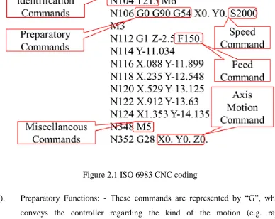
[image:30.595.121.510.340.648.2]ISO 6983 (GM code) is a part of computer aided engineering, mostly used in automation. It is a common name in NC programming, which remained unchanged since the development of first NC machine tool. In GM code programming the operator tells the computerized machine unit “how to make”. The “how to make” defines the instructions of where, how and what path to move. The ISO 6983 CNC coding is based on five specifications (ISO 6983-1, 1982) as shown in Figure 2.1.
Figure 2.1 ISO 6983 CNC coding
(i). Preparatory Functions: - These commands are represented by “G”, which conveys the controller regarding the kind of the motion (e.g. rapid positioning, linear or circular feed, fixed cycle). Up to date, there are around hundred commands in use from G0 to G99.
11 (iii). Axis Motion Commands: - These commands define the absolute or
incremental positions of machine tool axis represented by X, Y, Z, A, B, C. (iv). Feed and Speed Commands: - These commands define the feed rate and
spindle speed, represented by “F” and “S” respectively.
(v). Identification Commands: - These commands define the line number and cutting tool selection function, represented by “N” and “T” respectively. Although with the introduction of minicomputers and microcomputers, a massive improvement was achieved in the capabilities of CNC machine tool such as; multi axis, multi tool and multi processes. However, with this development towards flexible manufacturing environment, the programming tasks became more complex and difficult (Newman et al., 2008). The aim of flexible manufacturing was to make the CNC systems more interoperable, adaptable, open, intelligent and network portable (Mehrabi et al., 2000; Mehrabi et al., 2002). In order to fulfil these requirements, the current data interface model was found to have limited capabilities. There are number of problems that were found in ISO 6983 (Suh et al., 2003; Xu & He, 2004), which are summarized below.
(i). The ISO 6983 language is focused on programming the path of the cutter centre location with respect to the machine axis, rather than the machining tasks with respect to the part (Suh et al., 2002; Suh et al., 2003; Xu & He, 2004; Yusof et al., 2011).
(ii). The standard defines the syntax of program statements, but in most cases leaves the semantics unclear, together with low level limited control over program execution. These programs become machine dependent when processed in a CAM system by machine specific post processor (Xu & He, 2004; Xu & Newman, 2006; Yusof et al., 2011).
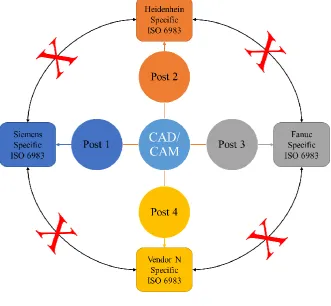
12
Figure 2.2 ISO 6983 vendor dependency environment
(iv). The flow of information from design to manufacturing is uni-directional. There is not any feedback of data in ISO 6983 as shown in Figure 2.3. Therefore the last minute changes and modifications of machining problems on shop floor are hardly possible (Sääski et al., 2005; Xu & He, 2004).
Figure 2.3 Current manufacturing system information flow
(v). The control of program execution at the machine is limited. Therefore it is very difficult to make changes in program at workshop (Xu & He, 2004). (vi). The CAD data is not directly used on the machine tool. It is processed by the
[image:32.595.111.522.549.635.2]13 incomplete data set makes verification and simulations very difficult (Xu & He, 2004).
(vii). This standard does not support today’s demand in the area of five axis milling or high speed machining, because it is incapable to process Spline data (Sääski et al., 2005; Xu & He, 2004).
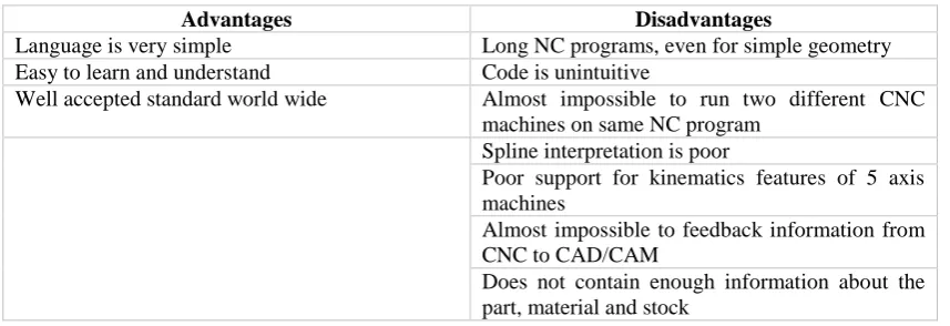
[image:33.595.107.536.276.423.2]Apart from these limitations, some other advantages and disadvantages of ISO 6983 are highlighted by (Krzic et al., 2009) as summarized in Table 2.1.
Table 2.1 ISO 6983 advantages and disadvantages
Advantages Disadvantages
Language is very simple Long NC programs, even for simple geometry
Easy to learn and understand Code is unintuitive
Well accepted standard world wide Almost impossible to run two different CNC
machines on same NC program Spline interpretation is poor
Poor support for kinematics features of 5 axis machines
Almost impossible to feedback information from CNC to CAD/CAM
Does not contain enough information about the part, material and stock
From the limitations of ISO 6983, it is clear that there are two major issues: interoperability and adaptability of CNC machines that need to be addressed for achieving the tasks of flexible manufacturing. Because of the fact that the current CNC machine tool follows the GM code program, which contains only “how-to-do” information, therefore, it is impossible to implement intelligent and optimization features on CNC (Xu & Newman, 2006). Due to these drawbacks, the need of new data interface model occurred. However in reality, these GM code programs are still very valuable because they integrate the micro-process plan with operator experience (Shin et al., 2007). This is one of the reason to include GM code working environment in this research.
14 exchange between CAD and CAM systems. The result was the ISO 10303 standard commonly known as STEP (Krzic et al., 2009).
2.4 ISO 10303
ISO 10303 standard is a mechanism to describe computer interpretable definitions of product characteristics (physical and functional) throughout its life cycle. According to the documentation of ISO 10303 standard, the objective of the STEP is “to provide a mean of describing the product data throughout the life cycle of a product, which is independent from any particular computer system”(ISO, 1994a; Sääski et al., 2005). Moreover, according to Fowler, the main objectives of STEP also includes the creation of a single standard which covers all the aspects of CAD/CAM data exchange with the implementation and acceptance by industry (Fowler, 1995).
2.4.1 Antiquity of ISO 10303
15 The next significant development in STEP occurred during year 2002. Where the capabilities of STEP was expanded in different industries (automotive, electronic manufacturing, aerospace and electrical etc) with the introduction of AP 202, AP 209, AP 210, AP 212, AP 214, AP 224, AP 225, AP 227 and AP 232. After that, the next development in the STEP was the introduction of STEP modular architecture. Modular architecture solved the problems emerging from large data structures. Currently, a new AP 242 is being developed for geometric dimensions and tolerance in combination with AP 203 and AP 214 (Safaieh et al., 2013).
2.4.2 Building of STEP
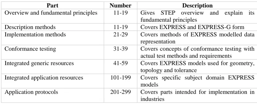
[image:35.595.109.526.436.606.2]This standard is separated into many parts namely: description method, information models, application protocols, implementation methods and conformance tools. These parts are represented by numbers, the total numbers are around 120 as described in Table 2.2.
Table 2.2 STEP standard parts
Part Number Description
Overview and fundamental principles 11-19 Gives STEP overview and explain its
fundamental principles
Description methods 11-19 Covers EXPRESS and EXPRESS-G form
Implementation methods 21-29 Covers methods of EXPRESS modelled data
representation
Conformance testing 31-39 Covers concepts of conformance testing with
actual test methods and requirements
Integrated generic resources 41-59 Covers EXPRESS models used for geometry,
topology and tolerance
Integrated application resources 101-199 Covers specific subject domain EXPRESS
models
Application protocols 201-299 Covers parts intended for implementation in
industries
2.4.2.1 Description Methods
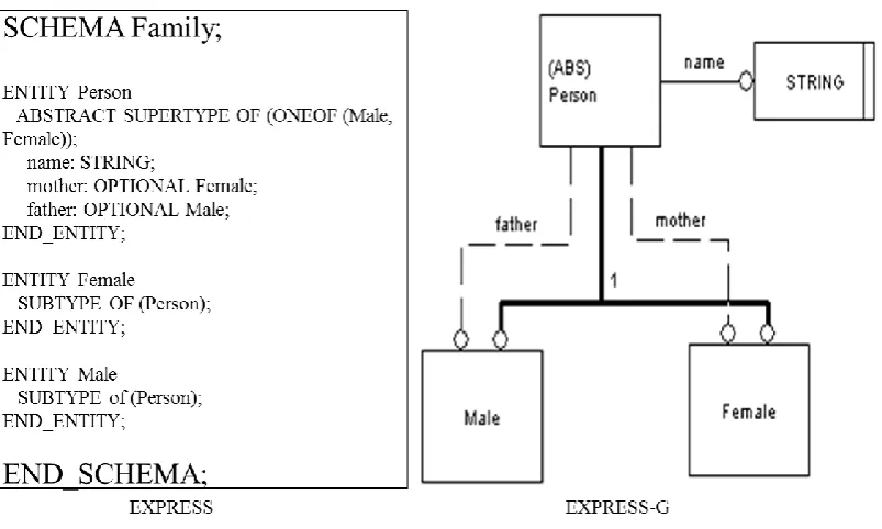
16 entities, the attributes and constraints are encapsulated, which restricts the value of attributes (Zha, 2006). The EXPRESS language also have a graphical form called EXPRESS-G. EXPRESS-G shows all the features in form of graphics such as: entities in solid boxes, simple data in solid box with double line and data type in box with dashed borders. Figure 2.4 shows the example of a description method based on EXPRESS and EXPRESS-G.
Figure 2.4 Example of EXPRESS and EXPRESS-G schema
2.4.2.2 Implementation Methods
For the implementation of STEP, additional methods are need to be defined. Several technologies are introduced by ISO 10303 because EXPRESS language does not define any method of implementation.
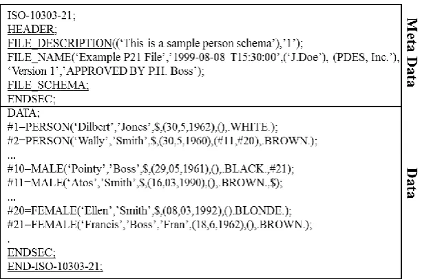
17 between parentheses “()” and separated by commas “,” and finally ends with a semi colon “;” as shown in Figure 2.5. In addition, ISO 10303-21 physical file also contains special tokens “$” and “*”, which represent, object values not omitted and object value can be defined from other values, respectively.
Figure 2.5 Example of ISO 10303-21 physical file
(ii). STEP Data Access Interface (SDAI): - This methods implements the STEP by means of binding the EXPRESS data with computer programming languages. In this method, the binding is classified into two approaches: early and late. In early binding approach, the entities of EXPRESS schemas are converted into C++ or JAVA classes. On other hand, late binding approach uses EXPRESS entity dictionaries for accessing data, but this approach is not suitable for large data systems. For such systems, a mixed binding approach is advantageous. Currently, there are four established standards available for SDAI.
a. SDAI (DIS, 1996)
b. C++ binding to SDAI (10303-23, 1998) c. C language binding of SDAI (10303-24, 1998) d. JAVATM binding to the SDAI (10303-27, 1998)
18 (XML) form (TC184, 2004). The implementation of XML in STEP is based on two levels: lower and upper. In lower level, CAD authorized systems can read and write data sets, whereas, in upper level, the modernization of STEP data sets are performed by means of inserting information from mapping tables into the XML data. Figure 2.6 shows the example of ISO 10303-28 file, also known as STEP part 28 file.
Figure 2.6 Example of ISO 10303-28 physical file (Lee et al., 2006)
Among all these methods, the most popular are STEP part 21 for offline manufacturing and STEP part 28 for online manufacturing or e-manufacturing.
2.4.2.3 Conformance Testing
Currently, there is no formal testing system in place for APs, whereas STEP provides these facilities in 30 parts and has been proposed for 300 parts (Kramer & Xu, 2009).
2.4.2.4 Integrated Resources
19 (i). The EXPRESS models for basic product data representation, which are called
STEP integrated generic resources.
(ii). The EXPRESS models for widely applicable type of product data like drafting (Parks & Fox, 1991), kinematics (10303-105, 1996) and finite element analysis (10303-107, 1996). These models are commonly known as STEP integrated application resources.
(iii). These models are same as STEP integrated generic resources. Only difference in these models is of the data representation which was developed for other ISO standards but adopted by STEP. These are models known as generic resources from other ISO standards.
2.4.2.5 Application Protocols
20 Table 2.3 List of Application Protocols
AP Description
201 Explicit Drafting
202 Associative Drafting
203 Configuration control design
204 Mechanical design using boundary representation
205 Mechanical design using surface representation
206 Mechanical design using wireframe representation
207 Sheet metal dies and blocks
208 Life cycle product change process
209 Design through analysis of composite and metallic structure
210 Electronic printed circuit assembly
211 Electronic test diagnostics and remanufacture
212 Electro technical plants
213 Numerical control process plans for machined parts
214 Core data for automotive mechanical design processes
215 Ship arrangements
216 Ship moulded forms
217 Ship piping
218 Ship structures
219 Dimensional inspection process planning for CMMs
220 Printed circuit assembly manufacturing planning
221 Functional data and schematic representations for process plans
222 Design engineering to manufacturing for composite structures
223 Exchange of design and manufacturing DPD for composites
224 Mechanical product definition for process planning
225 Structural building elements using explicit shape rep
226 Shipbuilding mechanical system
227 Plant spatial configuration
228 Building services
229 Design and manufacturing information for forged parts
230 Building structure frame steelwork
231 Process engineering data
232 Technical data packaging
233 Systems engineering data representation
234 Ship operational logos, records and messages
235 Materials information for products
236 Furniture product and project
237 Computational fluid dynamics
238 Integrated CNC machining
239 Product life cycle support
240 Process Planning
21 (i). AAM: - This model represents the activities and data flow information. This is a formal document which describes a portion of the product life cycle (what process do I want to support)(Feeney, 2002). These models are built by using Integrated Definition of functional modelling (IDEF) 0 approach. This approach is an integrated family of methods for business analysis between different collaborative works. With the completion of AAM, stage an ARM has been built.
(ii). ARM: - This model denotes the piece of product information (what are the information requirements of the activity in industry terminology) (Feeney, 2002), which are needed for the particular application. The information of ARM is described by the information model via library of pre-existing definitions. The building of ARM is usually done by the experts where they decide what entities and their attributes should be defined. This model can be written in EXPRESS, EXPRESS-G or IDEF1, but mostly EXPRESS and EXPRESS-G are used.
(iii). AIM: - This is an EXPRESS model which contain exactly same information as ARM. Only difference is of information encoding in terms of the STEP integrated resources (how do I model the required information using STEP and EXPRESS) (Feeney, 2002; Wang & Xu, 2004). The encoding is done by using mapping tables, the format of which is formally defined and uniform across STEP.
(iv). UOF: - It is a subset of ARM of an AP containing entities and related constructs that support some specific functionality. A number of APs were produced containing UOFs (Kramer & Xu, 2009) such as: AP 219 contains UOFs of administrative_data, dimensional_measurement_analysis, feature_profile, functional_limitations and part_properties (10303-219, 2007).
(v). AIC: - It is an interpreted UOF in terms of the STEP integrated resources. The idea is that, an AIC developed for use in the AIM of one AP can be reused in other APs. Currently, over 20 AICs have become international standards (Kramer & Xu, 2009).
22 (Feeney, 2002). In AM of an AP the Module Integrated Model (MIM) is called an AIM. The MIM is a reinterpretation of the ARM using STEP integrated resources. The AMs are able to refer each other to build a complex functionality (Kramer & Xu, 2009).
(vii). CC: - It is the subset of an AP, which enables the implementation of very large and multi domain APs in STEP architecture (Kramer & Xu, 2009) such as: AP214 has 20 CCs (10303-214, 1997; Nielsen & Kjellberg, 2000) and AP 238 has 4 CCs (10303-238, 2007).
2.4.3 Architecture of STEP
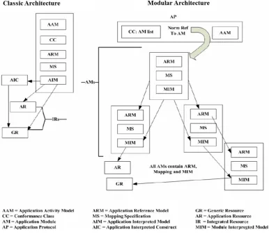
ISO 10303 is the most successful product data exchange standard. Its structure is recognized by two approaches: classic and modular as shown in Figure 2.7. As STEP is composed of APs, which contains activity model and conformance class. In the classic approach of STEP architecture, the AP is composed of AAM, CC, ARM, mapping and AIM. In this approach, there is a separate module for each of the components of AP. The information of APs is processed by the AICs to exchange common product data to two or more APs. While implementing classic approach in product data integration, some limitations had been found such as: high cost, document duplication and repetition and less interoperability in APs (Batres et al., 2007; Kramer & Xu, 2009; Le Duigou et al., 2009; Mehta et al., 2009). In order to overcome these drawbacks, some provisions were proposed in a classic approach (Feeney, 2002; Gielingh, 2008). The result of these provisions was the introduction of modular architecture of STEP.
23 (i). Reduce the high cost and lengthy time to develop an AP.
(ii). Enabling the implementation of a combination of multiple APs. (iii). Enabling application software reuse.
(iv). Eliminate duplication and repeated documentation of the same requirements in different APs.
(v). Reuse data generated by an implementation of one or more APs.
[image:43.595.121.508.216.553.2]
Figure 2.7 STEP architecture approaches (Fowler, 1995)
24 2.5 STEP-NC
As ISO 10303 standard resolves the problems relating to the product data exchange between CAD, CAPP and CAM systems. Therefore for establishing a seamless data flow between CAM and CNC, a new standard, ISO 14649, was introduced commonly known as STEP-Compliant Numerical Control or STEP-NC in short. This standard offers the possibility of seamless data integration of application throughout design to manufacturing cycle (Kramer & Xu, 2009). Currently, the attention of ISO is on the development of STEP manufacturing environment, which includes STEP in, STEP out and STEP throughout (Shin et al., 2007). The aim of STEP-NC is to provide remedies for the shortcomings of ISO 6983 by specifying machining processes rather than tool motion. It is done by using object and feature oriented concept of working steps which provides a seamless link in CAx to make CNC more open, interoperable, portable, adoptable, flexible and intelligent. The major benefit of STEP-NC is that, it uses existing data models of ISO 10303 for enabling of smooth and seamless information exchange in CAx (Cai et al., 2005). ISO 14649 contains high degree of information sets, which includes “What-to-make” (geometry) and “How-to-make” (process plan) (Shin et al., 2007).
2.5.1 Versions of STEP-NC
Currently, there are two versions of STEP-NC (ISO 14649 and ISO 10303-238) that are under development by two different sub committees of Technical Committee (TC) 184 under ISO.
2.5.1.1 ISO 14649
153
7REFERENCES
10303-23, I. (1998). ISO Committee Draft 10303-23: Industrial automation systems and integration–Product data representation and exchange–Part23: Implementation methods: C++ language binding to the standard data access interface ISO TC184/SC4 N.
10303-24, I. (1998). ISO Committee Draft 10303-24: Industrial automation systems and integration–Product data representation and exchange–Part24: Implementation methods: C language binding of standard data access interface ISO TC184/SC4 N.
10303-27, I. (1998). ISO Committee Draft 10303-27: Industrial automation systems and integration–Product data representation and exchange–Part27: Implementation methods: JAVATM programming language binding to the standard data access interface with internet/intranet extensions ISO TC184/SC4 N.
10303-105, I. (1996). ISO Committee Draft 10303-105: Industrial automation systems and integration–Product data representation and exchange–Part105: Integrated application resource: Kinematics ISO TC184/SC4 N.
10303-107, I. (1996). ISO Committee Draft 10303-107: Industrial automation systems and integration–Product data representation and exchange–Part107: Integrated application resource: Finite element analysis definition relationships ISO TC184/SC4 N.
10303-214, I. (1997). ISO Committee Draft 10303-214: Industrial automation systems and integration–Product data representation and exchange–Part214: Application Protocol: Core data for automotive mechanical design process
ISO TC184/SC4 N (Vol. 577).
10303-219, I. (2007). ISO Committee Draft 10303-219: Industrial automation systems and integration–Product data representation and exchange–Part219: Application Protocol: Dimensional inspection information exchange ISO TC184/SC4 N.
10303-238, I. (2007). ISO Committee Draft 10303-238: Industrial automation systems and integration–Product data representation and exchange–Part238: Application Protocol: Application interpreted model for computerized numerical controllers ISO TC184/SC4 N.
Albert, M. (2000). FEATURES-EMPHASIS: CNC and CAM-STEP NC-The end of G-Codes?-Cover story. One day soon, the only input the CNC will need is a digital part model obtained directly from the Web. Modern Machine Shop, 73(2), 70-85.
Asato, O., Kato, E., Inamasu, R., & Porto, A. (2002). Analysis of open CNC architecture for machine tools. Journal of the Brazilian Society of Mechanical Sciences, 24(3), 208-212.
154 Balic, J., Klancnik, S., & Brezovnik, S. (2008). Feature extraction from CAD model
for milling strategy prediction. Strojniški vestnik, 54(5), 301-307.
Ball, A., Ding, L., & Patel, M. (2008). An approach to accessing product data across system and software revisions. Advanced Engineering Informatics, 22(2), 222-235.
Batres, R., West, M., Leal, D., Price, D., Masaki, K., Shimada, Y., Fuchino, T., & Naka, Y. (2007). An upper ontology based on ISO 15926. Computers & Chemical Engineering, 31(5), 519-534.
Benavente, J. C. T., Ferreira, J. C. E., Goulart, C. M., & Oliveira, V. G. d. (2013). A STEP-NC compliant system for the remote design and manufacture of mechanical components through the Internet. International Journal of Computer Integrated Manufacturing, 26(5), 412-428.
Bin, L., Yunfei, Z., & Xiaoqi, T. (2004). A research on open CNC system based on architecture/component software reuse technology. Computers in Industry, 55(1), 73-85.
Bishop, R. H. (2009). LabVIEW 2009 Student Edition. Upper Saddle River, NJ, USA: Prentice Hall Press.
Brecher, C., Verl, A., Lechler, A., & Servos, M. (2010). Open control systems: state of the art. Production Engineering, 4(2-3), 247-254.
Brecher, C., & Voss, M. (2005). Potenziale komponentenbasierter offener NCSteuerungssysteme. Fortschritt-Berichte VDI—Fertigungs-und Medizintechnik: Gemeinsame Lösungansätze. VDI Verlag, Düsseldorf, S121-S134.
Cai, J., Weyrich, M., & Berger, U. (2005). Ontological machining process data modelling for powertrain production in extended enterprise. Journal of Advanced Manufacturing Systems, 4(01), 69-82.
Calabrese, F., & Celentano, G. (2007). Design and realization of a STEP-NC compliant CNC embedded controller. Emerging Technologies and Factory Automation ETFA., Patras. IEEE. 1010-1017
Cha, J. M., Suh, S. H., Hascoet, J. Y., & Stroud, I. (2014). A roadmap for implementing new manufacturing technology based on STEP-NC. Journal of intelligent manufacturing, 1-15.
Chen, L., Yu, D., Zhang, H., Geng, C., & Dong, L. (2012). Design and implement of a modularized CNC interpreter based on the integration of tool path planning module. Computer Science and Automation Engineering (CSAE). IEEE. 613-616.
Chunhao, L., Lijin, G., & Jingdong, L. (2012). Research of motion control system based on PCI-1243. Digital Manufacturing and Automation (ICDMA). IEEE. 662-665.
Consortium, I. S.-N. (2003). Technical Report 3 of IMS Project (97006) STEP-compliant data interface for numerical controls (STEP-NC) Report Period
(Vol. 1).
Da Rocha, P., Diogne de Silva e Souza, R., & De Lima Tostes, M. E. (2010). Prototype CNC machine design. Industry Applications (INDUSCON), Sao Paulo. IEEE. 1-5.
Denkena, H., Tönshoff, J., Selle, A., Storr, S., Heusinger, S., & Rogers, G. (2002). Offline-Berechnung der Zerspankräfte in der NC-Programmierung.
Vorhersage der Zerspankräfte beim HSC-Schlichtfräsen.
155 exchange structure,” International Organization for Standardization, Geneva, Switzerland.
DIS, I. (1996). 10303-22, "Product data representation and exchange-part 22: Standard data access interface" TC184/SC4.
Dong, Y., Hu, L., Ruifeng, G., Jiangang, Y., & Pengfei, X. (2005). The research on real-time middleware for open architecture controller. Embedded and Real-Time Computing Systems and Applications. IEEE. 80-83.
Ekkachai, K., Komin, U., Chaopramualkul, W., Tantaworrasilp, A., Kwansud, P., Seekhao, P., Leelasawassuk, T., Tanta-Ngai, K., & Tungpimolrut, K. (2009). Design and development of an open architecture CNC controller for milling machine retrofitting. ICCAS-SICE, Fukuoka. IEEE. 5629-5632.
Elias, D., Yusof, Y., & Minhat, M. (2013). CNC machine system via STEP-NC data model and LabVIEW platform for milling operation. Open Systems (ICOS). IEEE. 27-31.
Elias, D., Yusof, Y., & Minhat, M. (2014). An open STEP-NC controller via labview platform. Applied Mechanics and Materials, 660, 873-877.
Elliott, C., Vijayakumar, V., Zink, W., & Hansen, R. (2007). National instruments LabVIEW: a programming environment for laboratory automation and measurement. Journal of the Association for Laboratory Automation, 12(1), 17-24.
Erdős, G., & Xirouchakis, P. (2003). STEP-NC data model developement for wire-EDM manufacturing. IFAC.
Ertell, G. G. (1969). Numerical control. New York, NY Wiley.
ESPRIT III, E. OSACA public document: Open system architecture for controls within automation systems EP 6379 & EP 9115 (OS2FIN4. DOC) Final Rep., Version (Vol. 1).
Feeney, A. B. (2002). The STEP modular architecture. Journal of Computing and Information Science in Engineering, 2(2), 132-135.
Fowler, J. (1995). STEP for data management, exchange and sharing.
Garrido Campos, J., & Hardwick, M. (2006). A traceability information model for CNC manufacturing. Computer-Aided Design, 38(5), 540-551.
Gielingh, W. (2008). An assessment of the current state of product data technologies.
Computer-Aided Design, 40(7), 750-759.
Groover, M. P. (2007). Automation, production systems, and computer-integrated manufacturing. Upper Saddle River, NJ, USA: Prentice Hall Press.
Guo, X., Liu, Y., Du, D., Yamazaki, K., & Fujishima, M. (2012). A universal NC program processor design and prototype implementation for CNC systems.
The International Journal of Advanced Manufacturing Technology, 60(5-8), 561-575.
Gutierrez, M. E., & Álvares, A. J. (2013). Development of a cnc router adherent to standard STEP-NC based on the controller advanced machine (EMC2). 22nd International Congress of Mechanical Engineering (COBEM). 8200-8213. Hamilton, K., Hascoet, J. Y., & Rauch, M. (2014). Implementing STEP-NC:
Exploring possibilities for the future of advanced manufacturing Modern Mechanical Engineering (pp. 199-239). Berlin Heidelberg: Springer.
Han, J., Pratt, M., & Regli, W. C. (2000). Manufacturing feature recognition from solid models: a status report. Robotics and Automation, IEEE Transactions, 16(6), 782-796.
156 Hardwick, M. (2001). STEP into Automatic Machining: STEP Tools, Inc.
Hardwick, M. (2004). On STEP-NC and the complexities of product data integration.
Journal of Computing and Information Science in Engineering, 4(1), 60-67. Hardwick, M., Zhao, Y. F., Proctor, F. M., Nassehi, A., Xu, X., Venkatesh, S.,
Odendahl, D., Xu, L., Hedlind, M., & Lundgren, M. (2013). A roadmap for STEP-NC-enabled interoperable manufacturing. The International Journal of Advanced Manufacturing Technology, 68(5-8), 1023-1037.
Houshmand, M., & Valilai, O. F. (2012). LAYMOD: a layered and modular platform for CAx product data integration based on the modular architecture of the standard for exchange of product data. International Journal of Computer Integrated Manufacturing, 25(6), 473-487.
ISO 6983-1. (1982). ISO 6983/1 Numerical control of machines-program format and definition of address words-part 1: data format for positioning, line and contouring control systems International Organization of Standard. Vernier, Geneva, Switzerland: ISO.
ISO. (1994a). 10303-1 TC184/SC4: Product data representation and exchange—part 1: overview and fundamental principles International Standard. Vernier, Geneva, Switzerland: ISO.
ISO. (2002a). 14649-1. Industrial automation systems and integration physical device control-data model for computerized numerical controllers-Part 1: Overview and fundamental principles draft international standard USA: ISO TC184/SC4.
ISO. (2002b). 14649-10. Industrial automation systems and integration physical device control-data model for computerized numerical controllers-Part 10: General process data. USA: ISO TC184/SC4.
ISO. (2002c). 14649-11. Industrial automation systems and integration physical device control-data model for computerized numerical controllers-Part 11: Process data for milling. USA: ISO TC184/SC4.
ISO. (2002d). 14649-12. Industrial automation systems and integration physical device control-data model for computerized numerical controllers-Part 12: Process data for turning. USA: ISO TC184/SC4.
ISO. (2002e). 14649-111. Industrial automation systems and integration physical device control-data model for computerized numerical controllers-Part 111: Tools for milling. USA: ISO TC184/SC4.
ISO. (2002f). 14649-121. Industrial automation systems and integration physical device control-data model for computerized numerical controllers-Part 121: Tools for turning. USA: ISO TC184/SC4.
ISO, C. (1991). 10303-1:" Product Data Representation and Exchange-Part 1: Overview and Fundamental Principles.". TC, 184.
ISO, I. (1994b). 10303-1. Industrial automation systems and integration—Product data representation and exchange—Part, 1.
ISO, T. (1994c). 184/SC 4, ISO 10303-11: 1994 Industrial automation systems and integration-Product data representation and exchange-Part 11: Description methods: The EXPRESS language reference manual International Organization for Standardization. Vernier, Geneva, Switzerland: ISO.
Khanna, A., Kumar, A., Bhatnagar, A., Tyagi, R., & Srivastava, S. (2013). Low-cost production CNC system. Intelligent Systems and Control (ISCO), Coimbatore, Tamil Nadu, India. IEEE. 523-528.
157 Kramer, T. R., Proctor, F., Xu, X., & Michaloski, J. (2006). Run-time interpretation of STEP-NC: implementation and performance. International Journal of Computer Integrated Manufacturing, 19(6), 495-507.
Krzic, P., Stoic, A., & Kopac, J. (2009). STEP-NC: A new programming code for the CNC machines. Strojniški vestnik, 55(6), 406-417.
LabVIEW, F. (2009). National Instruments (pp. 78730-75039). Texas, USA: Austin. Laguionie, R., Rauch, M., & Hascoët, J. Y. (2009). Toolpaths programming in an
intelligent STEP-NC manufacturing context. Journal of Machine Engineering, 8(1), 33-43.
Laguionie, R., Rauch, M., Hascoët, J. Y., & Suh, S. H. (2011). An extended manufacturing integrated system for feature-based manufacturing with STEP-NC. International Journal of Computer Integrated Manufacturing, 24(9), 785-799.
Lan, H., Liu, R., & Zhang, C. (2008). A multi-agent-based intelligent STEP-NC controller for CNC machine tools. International Journal of Production Research, 46(14), 3887-3907.
Lan, H., Zhang, C., & Liu, R. (2006). A Framework for Intelligent STEP-NC Controller Based on Multi-agent.
Le Duigou, J., Bernard, A., Perry, N., & Delplace, J. C. (2009). Global approach for technical data management. Application to ship equipment part families.
CIRP Journal of Manufacturing Science and Technology, 1(3), 185-190. Lee, W., Bang, Y., Ryou, M., Kwon, W., & Jee, H. (2006). Development of a
PC-based milling machine operated by STEP-NC in XML format. International Journal of Computer Integrated Manufacturing, 19(6), 593-602.
Li, P., Gao, T., Wang, J., & Liu, H. (2010). Open architecture of CNC system research based on CAD graph-driven technology. Robotics and Computer-Integrated Manufacturing, 26(6), 720-724.
Li, P., Hu, T., & Zhang, C. (2011). A unified communication framework for intelligent integrated CNC on the shop floor. Procedia Engineering, 15, 840-847.
Liana, S. Y., Hecker, R. L., & Landers, R. G. (2004). Machining process monitoring and control: the state-of-the-art. Journal of manufacturing science and engineering, 126(2), 297-310.
Ma, X. B., Han, Z. Y., Wang, Y. Z., & Fu, H. Y. (2007). Development of a PC-based open architecture software-CNC system. Chinese Journal of Aeronautics, 20(3), 272-281.
Maoyue, L., Hongya, F., Yuan, L., & Zhenyu, H. (2009a). An intelligent controller based on constant cutting force for 5-axis milling. Information Technology and Computer Science. IEEE. 237-241.
Maoyue, L., Hongya, F., Yuan, L., & Zhenyu, H. (2009b). Research on reusable and configurable intelligent machining system. Industrial Electronics and Applications. IEEE. 3130-3133.
Mehrabi, M. G., Ulsoy, A. G., & Koren, Y. (2000). Reconfigurable manufacturing systems: key to future manufacturing. Journal of intelligent manufacturing, 11(4), 403-419.
Mehrabi, M. G., Ulsoy, A. G., Koren, Y., & Heytler, P. (2002). Trends and perspectives in flexible and reconfigurable manufacturing systems. Journal of intelligent manufacturing, 13(2), 135-146.
158 Mekid, S., Pruschek, P., & Hernandez, J. (2009). Beyond intelligent manufacturing: A new generation of flexible intelligent NC machines. Mechanism and Machine Theory, 44(2), 466-476.
Minhat, M., Vyatkin, V., Xu, X., Wong, S., & Al Bayaa, Z. (2009). A novel open CNC architecture based on STEP-NC data model and IEC 61499 function blocks. Robotics and Computer-Integrated Manufacturing, 25(3), 560-569. Morales Velazquez, L., Romero Troncoso, R. d. J., Osornio Rios, R. A., Herrera
Ruiz, G., & Cabal Yepez, E. (2010). Open architecture system based on a reconfigurable hardware software multi agent platform for CNC machines.
Journal of Systems Architecture, 56(9), 407-418.
Mori, M., Yamazaki, K., Fujishima, M., Liu, J., & Furukawa, N. (2001). A study on development of an open servo system for intelligent control of a CNC machine tool. CIRP Annals-Manufacturing Technology, 50(1), 247-250. Mortenson, M. E. (1985). Geometric modeling.
Müller, P., & Hyun, Y. (2001). ESPRIT Projekt EP29708 STEP-Compliant data interface of numerical controls (STEPNC) Final report, STEP-NC Consorcium (pp. 1-28).
Nacsa, J. (2001). Comparison of three different open architecture controllers. IFAC MIM, Prague. 2-4.
Nassehi, A. (2007). The realisation of CAD/CAM/CNC interoperability in prismatic part manufacturing. Dissertation Abstracts International, 68(4).
Nassehi, A., Liu, R., & Newman, S. (2007). A new software platform to support feature-based process planning for interoperable STEP-NC manufacture.
International Journal of Computer Integrated Manufacturing, 20(7), 669-683.
Nassehi, A., Newman, S., & Allen, R. (2006). The application of multi-agent systems for STEP-NC computer aided process planning of prismatic components.
International Journal of Machine Tools and Manufacture, 46(5), 559-574. Newman, S., Allen, R., & Rosso Jr, R. (2003). CAD/CAM solutions for
STEP-compliant CNC manufacture. International Journal of Computer Integrated Manufacturing, 16(7-8), 590-597.
Newman, S., Nassehi, A., Xu, X., Rosso, R., Wang, L., Yusof, Y., Ali, L., Liu, R., Zheng, L., & Kumar, S. (2008). Strategic advantages of interoperability for global manufacturing using CNC technology. Robotics and Computer-Integrated Manufacturing, 24(6), 699-708.
Nielsen, J., & Kjellberg, T. (2000). The ISO 10303-214 process model as a core for a process planning tool. International CIRP Design Seminar.
Pabolu, V. K., & Srinivas, S. (2010). Design and implementation of a three dimensional CNC machine. International Journal on Computer Science and Engineering, 2(8), 2567-2570.
Pacheco, N. d. O., Harbs, E., Rosso Jr, R. S., Hounsell, M. d. S., & Ferreira, J. C. E. (2012). Application of the step-nc standard in a computer numerical controlled machining device. ABCM Symposium Series in Mechatronics, 5, 713-723.
Park, S., Kim, S. H., & Cho, H. (2006). Kernel software for efficiently building, re-configuring, and distributing an open CNC controller. The International Journal of Advanced Manufacturing Technology, 27(7), 788-796.
Parks, C. H. (1984). IGES as an interchange format for integrated circuit design.