International Journal of Innovative Technology and Exploring Engineering (IJITEE) ISSN: 2278-3075, Volume-8 Issue-10, August 2019
Abstract: A proportional integral derivative (PID) and proportional integral derivative acceleration (PIDA) controller have been designed for voltage regulation in power system. The controller (i.e. PID and PIDA) has been proposed via frequency response matching of desired reference model with that of system model transfer function. The proposed PID controller has been designed using one point frequency response matching as well as pole placement technique, while PIDA controller has been designed using two point frequency response matching by equating desired set-point closed loop reference model with that of closed loop transfer function of system model. The response of the proposed PIDA controller shows improved performance for automatic voltage regulator (AVR) system in comparison with recently available literature. The proposed PID and PIDA controllers provide fast and smooth response for an AVR system. The advantages associated with the PIDA controller for an AVR system is to reduce rise time, percentage overshoot and improved robustness, stability margin.
keywords: Frequency response matching, AVR, PID controller, PIDA controller, robustness, integral of square error (ISE).
I. INTRODUCTION
Automatic voltage regulator (AVR) system is required to maintain the terminal voltage and stability of power system through excitation control of synchronous generator [1]. The PIDA controller is used to provide fast and smooth response as well as more suitable for higher order plant, which is used to maintain voltage regulation and reactive power generation of generator and load within specified limits. Day-by-day complexity in power system is increasing, so that terminal voltage of an alternator along with reactive power is varying rapidly and sometimes it become unstable. A lots of controller has been proposed for AVR system via different control approach like fractional order (FO) PID (FOPID) [2–7], PIDA [8–10], direct synthesis (DS) technique [11], Fuzzy logic controller (FLC) [12–14], sliding mode control [15], artificial intelligence technique [16–20].
FOPID controller has been proposed based on particle swarm optimization (PSO) for voltage regulation of power system by M. Zamini et al. [2] and a noval performance criterion has been proposed to obtain FOPID controller gain parameter based on time domain and frequency domain. Tang et al. [3] presents FOPID controller based on chaotic ant swarm optimization technique for an AVR system.
Revised Manuscript Received on August 05, 2019
Anand Kumar, Department of Electrical Engineering, National Institute of technology, Patna-800005, India.
Md Nishat Anwar, Department of Electrical Engineering, National Institute of technology, Patna-800005, India.
Camacho and Mermoud [4] have been proposed a fractional order model reference adaptive controller (FOMRAC) design and considered genetic algorithm (GA) optimization technique for FOMRAC controller gain parameter in an AVR system. Das and Pan [5] have been proposed FOPID controller for voltage regulation of power system based on frequency domain design. Zeng et al. [6] has been designed FOPID controller using multi objective external optimization technique to obtain improved performance for an AVR system and considered integral of absolute error (IAE) as objective function in optimization technique to obtain PID controller gain parameter. Sikander et al. [7] has been proposed cuckoo search algorithm based on FOPID controller for AVR system and provides better accuracy and robustness of the system.
PIDA controller has been implemented in parallel form by Jung and Dorf [8] and controller gain parameters has been obtained by using location of root-locus. PIDA controller design has been proposed by Puangdownreong [9] based on a metaheuristic current search algorithm for an AVR system. Second order derivative PID controller design has been proposed for AVR system and its controller gain parameter has been obtained using PSO algorithm by Sahib [10]. PID controller design for an AVR system has been proposed by Anwar and Pan [11] based on direct synthesis approach.
Mukherjee and Ghoshal [12] present fuzzy PID controller design for an AVR system and the parameter of PID controller is optimized using intelligent particle swarm algorithm. Fuzzy P plus Fuzzy I plus Fuzzy D (FP+FI+FD) controller has been designed for an AVR system based on Fuzzy logic and its controller gain parameter is optimized using hybrid of GA and PSO (HGAPSO) algorithm by Shayeghi et al. [13]. A PID controller design has been developed for an AVR system based on a combined GA, radial basis function neural network (RBF-NN) and Sugeno fuzzy logic technique by Gizi et al. [14]. Ribeiro et al. [15] presents sliding mode control technique for an AVR and this technique is able to maintain stability and terminal voltage of synchronous generator.
Chaotic ant swarm (CAS) algorithm has been proposed to design PID controller for regulation of terminal voltage in synchronous generator by Zhu et al. [16]. Godze and Taplamacioglu [17] have been proposed optimal PID controller for voltage regulation of power system utilizing artificial bee colony optimization technique. The PID controller has been proposed by Hasanien [18] using Taguchi combined genetic algorithm technique for an AVR system. Optimal PID
A PID and PIDA Controller Design for an AVR
System using Frequency Response Matching
controller has been designed for an AVR system by Chatterjee and Mukherjee [19] based on teaching learning optimization technique and robustness of controller is also analyzed. PID controller design has been presented for an AVR system based on a combination of ant colony optimization and Nelder-Mead approach by Blondin et al [20]. Maslo et al. [21] proposed generalized model for excitation systems and also reduced higher order model to lower order standard model.
PIDA controller is better alternative for AVR system to exiting controller design in this area. The parameter of PID and PIDA controller is easily obtained by tuning the pole of the desired closed loop transfer function (CLTF) and also eliminate the problem associated with higher order process. The major contribution of the paper work are as following. PID controller design for AVR system using frequency
response matching with desired pole placement. PIDA controller has been proposed via two point
frequency response matching for an AVR system. Analysis of gain margin (GM) and phase margin (PM)
has been considered to ensure stability of AVR system. Maximum sensitivity and system parameter uncertainty
has been analyzed to confirm the robustness of PID and PIDA controller.
Analysis of Integral of square error (ISE) w.r.t time constant of desired closed loop transfer function for an AVR system.
The comparative analysis of the proposed PID and PIDA controller has been compared with available standard literature.
The paper work is well organized in five section. In section 1 consist of introduction of AVR system along with literature survey and main contribution of the paper. Dynamic of AVR system is discussed in section 2. Section 3 well described the PID and PIDA controller design methodology for an AVR system, while simulation results and its comparative analysis is demonstrated in section 4. Finally, conclusions of present work is explain.
II. DYNAMICSOFAVRSYSTEM
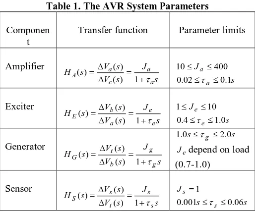
The AVR is used to control terminal voltage of an alternator to a pre-specified value. It consist of mainly four components which are amplifier, exciter, generator and sensor, which is shown in Fig. 3. [1]. The transfer function of each parameters of AVR system taken from Anwar and Pan [11], which is shown in table 1.
The unity negative feedback control structure as shown in Fig. 1 has been considered to control the terminal voltage of synchronous generator. The PID and PIDA controller have been designed to regulate the terminal voltage within specified limit with the following expression.
s k s k k s
KCPID( ) p i d (1)
2
)
( k s k s
s k k s
KCPIDA p i d a (2)
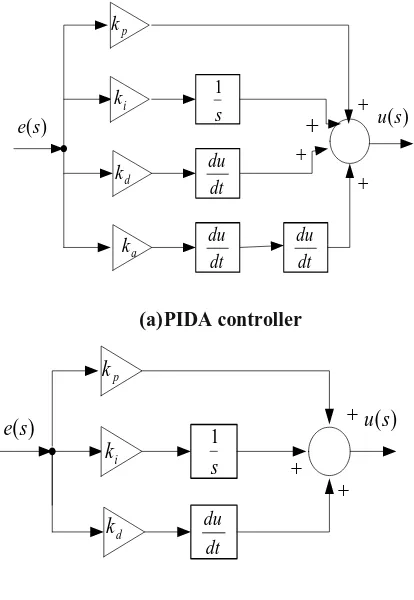
Eq. 2. Shows PIDA controller is a third order system, which is similar as PID controller except it has one additional acceleration gain parameter (ka). The PID and
PIDA controller takes the error signal e, and produces controller output signal u, to maintain output of the plant y with reference input r, while LD is the load disturbance of plant. KC(s), HP(s) and HS(s) are the controller, plant and
feedback transfer function, respectively. The major objective of the proposed controller is to reduce voltage regulation due to step load disturbance.
r e u y
)
(
s
K
CLoad disturbance (LD) ) (s
HP
) (s
[image:2.595.316.560.211.300.2]HS
Figure 1. Unity Negative Feedback Control System
s
1
dt du
) (s u )
(s e
p
k
dt du dt
du
i
k
d
k
a
k
(a) PIDA controller
s
1
dt du
) (s u
) (s
e
p
k
i
k
d
k
(b) PID controller
[image:2.595.326.533.331.631.2]International Journal of Innovative Technology and Exploring Engineering (IJITEE) ISSN: 2278-3075, Volume-8 Issue-10, August 2019
s J a a 1 s J e e 1 s J g g 1 s J s s 1 ) (s Vref
Ve(s) Vc(s) Va(s) Vb(s)
) (s VLD ) (s Vt ) (s Vs
Amplifier Exciter Generator
[image:3.595.180.417.55.164.2]Sensor ) (s Kc + - + Controller
Figure 3. Schematic Diagram Of AVR System Model With Controller
Table 1. The AVR System Parameters
Componen t
Transfer function Parameter limits
Amplifier s J s V s V s H a a c a
A
1 ) ( ) ( ) ( s J a a 1 . 0 02 . 0 400 10 Exciter s J s V s V s H e e a b
E
1 ) ( ) ( ) ( s J e e 0 . 1 4 . 0 10 1 Generator s J s V s V s H g g b t
G
1 ) ( ) ( ) ( s s g 2.0 0
.
1
e
J depend on load (0.7-1.0) Sensor s J s V s V s H s s t s
S
1 ) ( ) ( ) ( s s J s s 06 . 0 001 . 0 1
I. CONTROLLERDESIGNMETHODOLOGY
The controllers KC(s) (PID & PIDA) have been designed
using frequency response matching technique. In frequency response matching technique actual CLTF of the system model is approximated with desired CLTF at low frequency points. In that case, obtained controller is not physically realizable and need some suitable approximation to obtain controller like PI and PID form. The PID and PIDA controllers are used to improve stability and response of the terminal voltage of synchronous generator. The controller are able to reduce the settling time, maximum overshoot, rise time and improve steady state error.
A.PID controller design method:
Consider HR,Y(s) as the closed loop transfer function from )
(s Vref
to Vt(s) is expressed as
) ( ) ( ) ( ) ( ) ( 1 ) ( ) ( ) ( ) ( ) ( ) ( ) ( , s H s H s H s H s K s H s H s H s K s V s V s H S G E A C G E A C ref t y
R (3)
The desired reference model MR,Y(s)for AVR system as
given by r Y R Y R Y R s s D s N s M ) 1 ( 1 ) ( ) ( ) ( , , , (4) Where ) ( ) ( , , s D s N Y R Y R
is a transfer function in rational form, r is the order of desired CLTF, the time constant is the tuning parameter for AVR system.
The characteristics equation of closed loop transfer function as in Eq. (3) may be written as
0 ) ( ) ( ) ( ) ( ) (
1KC sHA sHE sHGsHS s (5)
The controller parameter is designed in frequency response matching technique by equating the closed loop transfer function HR,Y(s) with that of desired closed loop
transfer function MR,Y(s), which may be written as )
( )
( ,
, s M s
HRY RY (6)
The following aspects have been considered to achieve desired performance of AVR system using frequency response matching:
1.To achieve desired transient response of AVR system, the pole of the desired reference model at s1 may be considered as the pole of the closed-loop system which gives the following characteristics equation.
0 ) ( ) ( ) ( ) ( ) (
1KC sHAsHE sHGsHS s for s1 (7)
Or, ) ( ) ( ) ( ) ( 1 ) ( s H s H s H s H s K S G E A C
(8)
By using Eq. (1), Eq. (8) may be written as
X s H s H s H s H k k k s S G E A d i
p
1 ) ( ) ( ) ( ) ( 1 (9)
2.To obtain better steady state performance of the system by equating the frequency response of two system at very low frequency point ( say
0.001
rad/s) which results in the following equation.) ( )
( ,
, j M j
[image:3.595.171.428.193.407.2]) ( ) ( ) ( ) ( ) ( ) ( 1 ) ( ) ( ) ( ) ( , j M j H j H j H j H j K j H j H j H j K Y R S G E A C G E A C
(11)
The expression of the controller parameter is obtained by using Eq. (1) and (11) as given by
) ( ) ( ) ( ) ( ) ( ) ( ) ( ) ( 1 , j H j H j H j H j H j H j H j M j k j k k G E A S G E A Y R d i p (12) Assuming ) ( ) ( ) ( ) ( ) ( ) ( ) ( ) ( 1 ,
H j H j H j
j H j H j H j H j M Z G E A S G E A Y R ,
the Eq. (12) may be written as
Im[ ] Re)
(k k Z j Z j
kp di (13)
By separating real and imaginary parts of Eq. (13) following two equations are obtained.
] Re[Z
kp (14)
] Im[ ) 1 ( Z k
kd i
(15)
The Eqns. (9), (14) and (15) can be rearranged in matrix form as given by
] Im[ ] Re[ 1 0 0 0 1 1 1 Z Z X k k k d i p (16)
The PID controller gain will be obtained by solving the Eq. (16).
B.PIDA Controller design method
The PIDA controller has been designed using frequency response matching and the desired reference model transfer function MR,Y(s) is considered as same as in Eq. (4). The
controller is designed by equating the closed-loop set-point response transfer function with that of the desired reference model and it is expressed in mathematical form as
) ( )
( ,
, s M s
HRY RY (17)
The expression for the controller parameter may be obtained from Eq. (17) as given by
) ( ) ( ) ( ) ( ) ( ) ( ) ( ) ( 1 ) (
, H sH sH s
s H s H s H s H s M s K G E A S G E A Y R
C (18)
The controller
K
CPIDA(
s
)
as in Eq. (2) is approximatedwith direct synthesis (DS)controller KC(s) as in Eq. (18)
using the low frequency point matching method proposed by Anwar and Pan [11] and In brief, the method is discussed here. The controller
K
CPIDA(
s
)
and KC(s) is approximated atvery low frequency point ( say 00.001rad/s and 10.002
rad/s ) and it may be mathematically written as
C s j
j s PIDA
C s K s
K
()
)
( (19)
Eq. (19) is elaborated by using Eq. (2) and (18), which is written as ) ( ) ( ) ( ) ( ) ( ) ( ) ( ) ( 1 ) ( , 2 j H j H j H j H j H j H j H j M j k j k j k k G E A S G E A Y R a d i p (20) Assuming ) ( ) ( ) ( ) ( ) ( ) ( ) ( ) ( 1 ,
H j H j H j
j H j H j H j H j M Z G E A S G E A Y R ,
the Eq. (20) may be written as
Im[ ] Re) (
)
(kpka 2 jkd ki Z Z
(21)
By separating real and imaginary parts of Eq. (21) the following two equations are obtained.
] Re[
2
Z k
kp a (22)
] Im[ ) 1 ( Z k
kd i
(23)
With the two low-frequency points (0and 1),
four equations are obtained using Eq. (22) and (23) as given below. ] Im[ ] Re[ ] Im[ ] Re[ 0 1 0 0 0 1 0 1 0 0 0 1 1 1 0 0 1 1 2 1 0 0 2 0 Z Z Z Z k k k k a d i p (24)
The solution of Eq. (24) will yield the parameter of the PIDA controller.
II. SIMULATIONRESULTSANDDISCUSSIONS
Case study 1. An AVR system parameters taken from [11] as given by:
10
a
J , a0.1, Je1, e0.4 , Jg 1, g 1.0, Js1, 01 . 0 s .
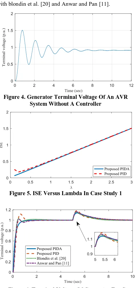
The terminal voltage unit step response of an AVR system without controller for case study 1 is as shown in Fig. 4 and observe that the percent overshoot (Mp ) is 50.6 %, the
settling time (ts) is 6.98 s, and steady state error (es) is 9.09
%.
The reference model has been considered for an AVR system at λ=0.2 and r=1. The proposed PID and PIDA
controller has been obtained as
s s
s
KCPID( )0.7140.4760.257 and
2 019 . 0 257 . 0 476 . 0 714 . 0 )
( s s
s s
KCPIDA , respectively. A test
signal step input is applied at t=0 sec, while load disturbance step input is applied at t=5 sec in the AVR system for case study 1. Fig. 5 shows that the ISE of an AVR system w.r.t time constant of desired closed loop transfer function. Fig. 6 demonstrate that the terminal voltage response for case study 1 with proposed PIDA controller is much better than the blondin et al. [20] and Anwar and Pan [11]. To estimate the performance of proposed controller in terms of maximum sensitivity ( max 1
1 ( ) ( )
0
k j p j
Ms
), percent overshoot
(Mp), and settling time (ts), the integral of square error
(ISE), GM and PM are considered.
International Journal of Innovative Technology and Exploring Engineering (IJITEE) ISSN: 2278-3075, Volume-8 Issue-10, August 2019
To check the robustness of controller, maximum sensitivity and uncertainty in system parameter is considered. For case study 1 with +50% variation in Jg and
g
[image:5.595.310.548.59.215.2] are considered and obtained simulation response for terminal voltage as shown in Fig. 8 and table 3 shows that the proposed PIDA has better performance in comparison with blondin et al. [20] and Anwar and Pan [11].
Figure 4. Generator Terminal Voltage Of An AVR System Without A Controller
[image:5.595.56.293.129.633.2]Figure 5. ISE Versus Lambda In Case Study 1
Figure 6. Terminal Voltage Of Generator For Case Study 1
[image:5.595.313.546.226.366.2]Figure 7. Controller Output For Case Study 1
Figure 8. Terminal Voltage Of Generator For Case Study 1 With +50% Variations In Jg And g
Figure 9. ISE Versus Lambda In Case Study 2
Case study 2. An AVR system parameters taken from [11] as given below:
12
a
J , a0.09, Je10,
e
0
.
5
, Jg 0.1,
g
1
.
0
, 1
s
J , s0.02.
The proposed PID controller has been designed with desired reference model at λ=0.2 and r=1 is
s s
s
KCPID( )0.6400.3780.168 . The proposed PIDA controller has been designed with desired reference model at λ=0.2 and r=1 is ( ) 1.175 0.694 0.485s 0.036s2
s s
KCPIDA . The
performance of AVR system is shown in Figs. 10, 11 and table 4 due step input test signal apply at t=0 sec and step disturbance test signal apply
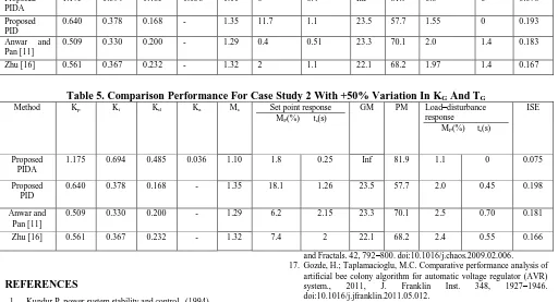
[image:5.595.314.548.395.569.2]The proposed PIDA shows much improved performance than the proposed PID , Anwar and Pan[11] and Zhu [16] in terms of set-point (percent overshoot , settling time ), load –disturbance (percent overshoot , settling time), ISE, GM and PM for nominal AVR system in case study 2.
To emphasize the robustness of proposed PID and PIDA controller, maximum sensitivity and +50% variation in Jg and g are considered. From Fig. 12 and table 5 observe that the terminal voltage of perturbed AVR system is stable and provide better performance than proposed PID, Anwar and Pan [11], Zhu [16].
III. CONCLUSION
In this paper, the PID and PIDA controllers have been proposed for an AVR system using frequency response matching. The maximum sensitivity, ISE, ts, %OS, GM, PM
[image:6.595.310.551.59.194.2]has been considered to demonstrate the performance of the proposed controller. The proposed PIDA controller results show much better than the prevalent design methods.
[image:6.595.42.558.384.785.2]Figure 10. Terminal Voltage Of Generator For Case Study 2
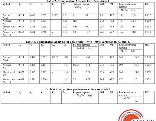
Table 2. Comparative Analysis For Case Study 1
Method Kp Ki Kd Ka Ms Set point response
MP(%) ts(s)
GM PM Load–disturbance
response MP(%) ts(s)
ISE
Proposed PIDA
0.714 0.476 0.257 0.019 1.03 0 0.8 Inf 87.2 13.9 2.58 0.132
Proposed PID
0.714 0.476 0.161 - 1.35 11.7 1 27.8 57.4 18.4 2.54 0.200
Blondin et al. [20]
0.673 0.595 0.262 - 1.33 3.06 0.91 25.4 66.9 15.5 2.07 0.158
Anwar and Pan [11]
0.652 0.434 0.236 - 1.32 2.0 1.22 26.1 67.7 16.4 2.80 0.173
Table 3. Comparative analysis for case study 1 with +50% variation in Kg and Tg
Method Kp Ki Kd Ka Ms Set point response
MP(%) ts(s)
GM PM Load–disturbance
response MP(%) ts(s)
ISE
Proposed PIDA
0.714 0.476 0.257 0.019 1.03 2.82 1.63 Inf 87.2 14.6 2.49 0.130
Proposed PID
0.714 0.476 0.161 - 1.35 18.32 1.14 27.8 57.4 19.5 2.46 0.206
Blondin et al. [20]
0.673 0.595 0.262 - 1.33 8.2 2.28 25.4 66.9 16.1 2.00 0.159
Anwar and Pan [11]
0.652 0.434 0.236 - 1.32 7.4 0.73 26.1 67.7 17.2 2.7 0.173
Table 4. Comparison performance for case study 2
Method Kp Ki Kd Ka Ms Set point response
MP(%) ts(s)
GM PM Load–disturbance
response MP(%)
ts(s)
International Journal of Innovative Technology and Exploring Engineering (IJITEE) ISSN: 2278-3075, Volume-8 Issue-10, August 2019
Proposed PIDA
1.175 0.694 0.485 0.036 1.10 0 0.4 Inf 81.9 0.8 0 0.076
Proposed PID
0.640 0.378 0.168 - 1.35 11.7 1.1 23.5 57.7 1.55 0 0.193
Anwar and Pan [11]
0.509 0.330 0.200 - 1.29 0.4 0.51 23.3 70.1 2.0 1.4 0.183
[image:7.595.46.558.57.334.2]Zhu [16] 0.561 0.367 0.232 - 1.32 2 1.1 22.1 68.2 1.97 1.4 0.167
Table 5. Comparison Performance For Case Study 2 With +50% Variation In KG And TG
Method Kp Ki Kd Ka Ms Set point response
MP(%) ts(s)
GM PM Load–disturbance
response MP(%) ts(s)
ISE
Proposed PIDA
1.175 0.694 0.485 0.036 1.10 1.8 0.25 Inf 81.9 1.1 0 0.075
Proposed PID
0.640 0.378 0.168 - 1.35 18.1 1.26 23.5 57.7 2.0 0.45 0.198
Anwar and Pan [11]
0.509 0.330 0.200 - 1.29 6.2 2.15 23.3 70.1 2.5 0.70 0.181
Zhu [16] 0.561 0.367 0.232 - 1.32 7.4 2 22.1 68.2 2.4 0.55 0.166
REFERENCES
1. Kundur P. power system stability and control., (1994)
2. Zamani, M.; Karimi-ghartemani, M.; Sadati, N.; Parniani, M. Design of a fractional order PID controller for an AVR using particle swarm
optimization. 2009, 17, 1380–1387.
doi:10.1016/j.conengprac.2009.07.005
3. Tang, Y.; Cui, M.; Hua, C.; Li, L.; Yang, Y. Optimum design of fractional order PIλDμcontroller for AVR system using chaotic ant swarm. Expert Syst. Appl., 2012, 39, 6887–6896. doi:10.1016/j.eswa.2012.01.007
4. Aguila-Camacho, N.; Duarte-Mermoud, M.A. Fractional adaptive control for an automatic voltage regulator. ISA Trans., (2013) 52, 807–815. doi:10.1016/j.isatra.2013.06.005.
5. Das, S.; Pan, I. On the Mixed Loop-Shaping Tradeoffs in Fractional-Order Control of the AVR System., (2014), 10, 1982–1991. 6. Zeng, G.Q.; Chen, J.; Dai, Y.X.; Li, L.M.; Zheng, C.W.; Chen, M.R.
Design of fractional order PID controller for automatic regulator voltage system based on multi-objective extremal optimization.
Neurocomputing., 2015 160, 173–184.
doi:10.1016/j.neucom.2015.02.051.
7. Sikander, A.; Thakur, P.; Bansal, R.C.; Rajasekar, S. A novel technique to design cuckoo search based FOPID controller for AVR in power systems. Comput. Electr. Eng., 2017 0, 1–14. doi:10.1016/j.compeleceng.2017.07.005
8. Jung, S.; Dorf, R.C. Analytic PIDA Controller Design Technique for A Third Order. IFAC Proc. 1996, Vol. 29, 2–7. doi:10.1016/S1474-6670(17)57819-2.
9. Puangdownreong, D. Application of Current Search to Optimum PIDA Controller Design. Intell. Control Autom., 2012, 03, 303–312. doi:10.4236/ica.2012.34035.
10. Sahib, M.A. A novel optimal PID plus second order derivative controller for AVR system., 2015, Eng. Sci. Technol. an Int. J. 18, 194–206. doi:10.1016/j.jestch.2014.11.006.
11. Anwar, M.N.; Pan, S. A Frequency Domain Design of PID Controller for an AVR System., 2014, J. Zhejiang Univ. C (Computers Electron. 15, 293–299. doi:10.1631/jzus.C1300218.
12. Mukherjee, V.; Ghoshal, S.P. Intelligent particle swarm optimized fuzzy PID controller for AVR system., 2007, 77, 1689–1698. doi:10.1016/j.epsr.2006.12.004.
13. Shayeghi, H.; Younesi, A.; Hashemi, Y. Optimal design of a robust discrete parallel FP + FI + FD controller for the Automatic Voltage Regulator system., 2015, Int. J. Electr. Power Energy Syst. 67, 66–75. doi:10.1016/j.ijepes.2014.11.013.
14. Al, A.J.H.; Mustafa, M.W.; Al-geelani, N.A.; Alsaedi, M.A. Sugeno fuzzy PID tuning , by genetic-neutral for AVR in electrical power generation., 2015, 28, 226–236 .
15. Ribeiro, R.L.A.; Neto, C.M.S.; Costa, F.B.; Rocha, T.O.A.; Barreto, R.L. A sliding-mode voltage regulator for salient pole synchronous generator. 2015, 129, 178–184.
16. Zhu, H.; Li, L.; Zhao, Y.; Guo, Y.; Yang, Y. CAS algorithm-based optimum design of PID controller in AVR system., 2009, Chaos, Solitons
and Fractals. 42, 792–800. doi:10.1016/j.chaos.2009.02.006. 17.Gozde, H.; Taplamacioglu, M.C. Comparative performance analysis of
artificial bee colony algorithm for automatic voltage regulator (AVR) system., 2011, J. Franklin Inst. 348, 1927–1946. doi:10.1016/j.jfranklin.2011.05.012.
18.Hasanien, H.M.; Member, S. Design Optimization of PID Controller in Automatic Voltage Regulator System Using Taguchi Combined Genetic Algorithm Method., 2013, 7, 825–831.
19.Chatterjee, S.; Mukherjee, V. PID controller for automatic voltage regulator using teaching-learning based optimization technique., 2016, Int. J. Electr. Power Energy Syst. 77, 418–429. doi:10.1016/j.ijepes.2015.11.010.
20.Blondin, M.J.; Sanchis, J.; Sicard, P.; Herrero, J.M. New optimal controller tuning method for an AVR system using a simplified Ant Colony Optimization with a new constrained Nelder–Mead algorithm.,
2018 Appl. Soft Comput. 62, 216–229.
doi:10.1016/j.asoc.2017.10.007.
21.Máslo, K.; Kasembe, A.; Kolcun, M. Simplification and unification of IEEE standard models for excitation systems., 2016, Electr. Power Syst. Res. 140, 132–138. doi:10.1016/j.epsr.2016.06.030.
AUTHORS PROFILE
ANAND KUMAR: He completed Bachelor of Engineering (B.E) degree in Electrical and Electronic Engineering from OIST, Bhopal, India, in 2013. Presently pursuing M.Tech-PhD dual degree program from NIT, Patna since 2015 in Department of Electrical Engineering. His area of interest includes linear control theory, power system stability control, PID controller, PIDA controller. List of publication includes 2 international conferences.