City, University of London Institutional Repository
Citation
:
Jones, S., Maiden, N., Manning, S. and Greenwood, J. (2004). Human Activity
Modelling in the Specification of Operational Requirements: Work in Progress. Paper
presented at the 26th International Conference on Software Engineering, 23 -28 May 2004,
Edinburgh, UK.
This is the unspecified version of the paper.
This version of the publication may differ from the final published
version.
Permanent repository link:
http://openaccess.city.ac.uk/2809/
Link to published version
:
Copyright and reuse:
City Research Online aims to make research
outputs of City, University of London available to a wider audience.
Copyright and Moral Rights remain with the author(s) and/or copyright
holders. URLs from City Research Online may be freely distributed and
linked to.
City Research Online:
http://openaccess.city.ac.uk/
[email protected]
Human Activity Modelling in the Specification of Operational Requirements:
Work in Progress
S. Jones, N.A.M. Maiden, S. Manning, J. Greenwood
1Centre for Human-Computer Interaction Design, City University, London
1National Air Traffic Services, London, UK
Contact e-mail:
[email protected]
Abstract
This paper describes our experience of integrating HCI concepts and techniques into a concurrent requirements engineering process called RESCUE. We focus on the use of a model of current human activity to inform specification of a future system. We show how human activity descriptions, written using a specially designed template, can facilitate the authoring of use case descriptions to be used in the elicitation of requirements for complex socio-technical systems. We describe our experience of using descriptions of human activity, written using the template, to support specification of operational requirements for DMAN, a system to support air traffic controllers in managing the departure of aircraft from airports. We end with a discussion of lessons learnt from our experience and present some ideas for future development of work in this area.
1.
Introduction
This paper describes our experience of applying HCI concepts and techniques in the specification of operational requirements for complex socio-technical systems in the domain of air traffic management. Our aim has been to develop a practical means by which requirements and systems engineers could use inputs from the HCI community to improve their practice in the specification of socio-technical systems. With this in mind, we have developed a process called RESCUE -Requirements Engineering with Scenarios for a User-centred Environment – a concurrent engineering approach, which allows us to integrate current HCI techniques and research perspectives with current best practice in relation to use-case based requirements specification.
RESCUE is aimed at the specification of operational
requirements – relatively high-level requirements of the kind which are sometimes referred to within the requirements community as ‘stakeholder requirements’. These requirements are typically concerned with the overall functionality of the socio-technical system, the division of labour between human and technical components of the system, and basic statements of non-functional requirements or constraints concerning usability, training, look and feel etc. Detailed specification of presentation in the user interface, user interaction and information architecture comes at a later stage in the development lifecycle. As an example of the typical level of detail of requirements included in an operational requirements document, a sample of requirements from the DMAN project (to be described below) is:
FR18: DMAN shall allow the ATCO [air traffic controller] to find a flight by stand or by destination.
LFR2: DMAN information shall not be displayed in a new HMI [Human Machine Interface], but shall be integrated to any controller working position as much as possible.
USR100: DMAN shall allow all controllers to retain flexibility in their operational procedures.
Thus, in terms of the taxonomy presented by Paech and Kohler [10], we are concerned primarily with:
• Decisions about the user tasks
• Understanding of the as-is activities
• Decisions about the to-be activities
• Decisions about the system responsibilities
• Understanding of the domain data relevant for a task
• Decisions about the system functions and
• Decisions about user-system interaction.
decisions, are made by a different team who specify systems in more detail and develop operational prototypes.
In this paper, we present an overview of the RESCUE process, and then describe in more detail the main part of the process in which HCI techniques and concepts are applied to facilitate the authoring of use case descriptions. We end with a discussion of lessons learnt from our experience and present some ideas for future development of work in this area.
2.
RESCUE Process Overview
Our process, RESCUE, was initially developed to specify operational requirements for a system called CORA-2, a system that will provide computerised assistance to air traffic controllers to resolve potential conflicts between aircraft. The RESCUE process has since been applied in the specification of requirements for DMAN, a system to support controllers in scheduling and managing the departure of aircraft from major European airports. This is the project from which examples presented in this paper will be drawn. The process is also currently being applied in the specification of MSP, a system for scheduling aircraft from gate to gate across multiple, multi-national sectors.
The RESCUE process was developed by academic researchers from the domains of HCI and requirements engineering, working with staff at Eurocontrol (the European Organisation for the Safety of Air Navigation), and was specifically targeted towards the needs of the domain of air traffic management. Thus RESCUE focuses on specification of requirements for critical systems, where development of new systems is evolutionary rather than revolutionary, and where the emphasis is on getting requirements right, rather than speed to market.
The CORA-2, DMAN and MSP projects in which RESCUE has been, and is being, applied, are part of the ASA (Automated Support to Air Traffic Services) programme, whose aim is to develop concepts, requirements and procedures for the provision of tools to enhance the air traffic control decision-making process. The ASA programme as a whole has adopted the principle of ‘human-centred automation’ [4]. This principle asserts that ‘the human bears the ultimate responsibility for the safety of the aviation system’, and that the controller must therefore remain in command of the system. The system, in turn, must provide information consistent with controllers’ responsibilities, and presented in a format meaningful to controllers in a given context so that controllers can monitor and understand what their automated systems are
doing. Proper consideration of the human element in the system therefore had to be included in our process.
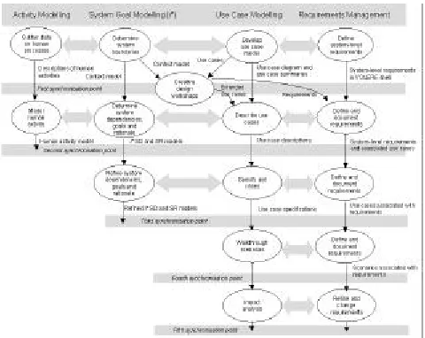
The RESCUE process consists of a number of sub-processes, organised into 4 ongoing streams. These streams run in parallel throughout the requirements specification stage of a project, and are mutually supportive. An overview of the process is provided in figure 1.
The four RESCUE streams focus on the areas of:
• Analysis of the current work domain using human
activity modelling (based on work described in [2], [12] and [14]) – this stream will be described in more detail below;
• System goal modelling using the i* goal modelling approach [15];
• Use case modelling and specification, followed by systematic scenario walkthroughs and scenario-driven
impact analyses using the SAVRE and CREWS-ECRITOIRE approaches [13];
• Requirements management using VOLERE [11] implemented in Rational’s requirements management tool RequisitePro in current rollouts of RESCUE.
In addition to these four streams, the RESCUE process uses the ACRE framework to select techniques for requirements acquisition [8], and creativity workshops,
[image:3.596.314.554.457.648.2]based on models of creative and innovative design [7], to discover candidate designs for the future system, and to analyse these designs for fit with the future system’s requirements.
Figure 1: Overview of the RESCUE process
process is checked at five different ‘synchronisation points’ during the process, as shown in figure 1.
3.
Modelling Human Activity in RESCUE: A
Case Study
In this paper, we focus on work in the activity modelling stream of RESCUE, and its implications for the rest of the process. This is the part of the process which draws most directly on HCI concepts and techniques. We describe this work using examples from the DMAN project.
3.1
Writing Human Activity Descriptions
As stated above, our aim in defining the human activity modelling stream in RESCUE was to develop a framework within which practicing requirements and systems engineers could capture and record information about human elements of an existing socio-technical system, in order to inform their specification of a future system. In particular, we were looking for a way in which HCI input could be harnessed to facilitate the authoring of use cases, which are central to the RESCUE process.
Human activity modelling (shown as ‘activity modelling’ in figure 1) focuses on the human users of the technical system, in line with the principle of human-centred automation defined in the previous section. In this stream, the project team must understand and model the controllers’ current work – its individual cognitive and non-cognitive components and social and co-operative elements – in order to facilitate the specification of technical systems that can better support that work. The stream consists of two sub-processes – data gathering and human activity modelling.
During the first sub-process (‘gather data on human processes’ in figure 1), data about all components of the activity model are gathered and recorded, initially in a relatively unstructured way. Techniques to gather this data are familiar to those in the domains of both HCI and RE and include: observation of current system use; informal scenario walkthroughs, using scenarios that describe how the current system is used; interviews with representative human users; and analysis of verbal protocols, or recordings of users talking through scenarios or tasks.
For DMAN, data was collected during the course of 2 half day visits to the control tower at Heathrow, which involved observation and interviews with controllers, and
1 scenario walkthrough session with air traffic controllers from Heathrow and Gatwick.
In the second sub-process (shown as ‘model human activity’ in figure 1) the project team creates a ‘human activity model’ (HAM) by generating a number of ‘human activity descriptions’ (HADs) corresponding to each of the major types of activity in the current system. This is analagous to the creation of a use case model, consisting of a number of related use case descriptions (UCDs).
A human activity model is a repository of information about various aspects of the current system. One key concept in an activity model is goals - states of the system which one or more actors wish to bring about. Goals may be: (i) high-level functional goals relating to the system as a whole, or local goals relating to particular tasks; (ii) individual goals, relating to single actors, or collective goals, relating to teams of actors; (iii) prescribed goals or non-prescribed goals. Other aspects to describe in a model include:
• Human actors - people involved in system;
• Actions - undertaken by actors to solve problems or achieve goals;
• Resources – means that are available to actors to achieve their goals, for example flight strips and information about a flight;
• Resource management strategies – how actors
achieve their goals with the resources available, for example writing down flight information on the flight strips;
• Contextual features – situational factors that influence decision-making, for example priorities are given to incoming aircraft; and
• Constraints - environmental properties that affect decisions, for example the size of the flight strip bay, which limits the number of strips to work with.
These categories of concepts were chosen with reference to the literature of task analysis (eg [2]), cognitive task analysis (eg [12]) and cognitive work analysis (eg [14]) as explained below.
Task analysis has been used a great deal within the HCI community for a number of purposes, including the elicitation of requirements for a new system. By modelling the existing system in terms of goals, tasks (or actions), objects (or resources) and other related concepts, a task analysis of an existing system helps clarify and organise the analyst’s knowledge about that system.
apply current concepts in cognitive psychology to the analysis of complex decision-making tasks such as those involved in air traffic control. A cognitive task analysis typically begins by identifying what type of knowledge is used in the task of interest, and therefore what knowledge representations should be used in modelling task performance. We decided to model activity in terms of a script-like representation, as the majority of the knowledge to be modelled was procedural, concerning the sequences of actions which take place under various circumstances. A script typically comprises a number of elements, including
• entry conditions: conditions that must be satisfied for the script to be activated – corresponding to the triggering event in our HAD template;
• results: conditions that will be true after the script is terminated – corresponding to goals in our template;
• props: objects or resources involved in the events described in the script;
• roles: groups of actions performed by particular
participants – corresponding to our actors;
• scenes: sequences of events that occur,
corresponding to our normal courses; and
• tracks: alternative scenarios corresponding to our variations
[3].
In addition to task analysis and CTA, we wished to draw on recent work on cognitive work analysis [14] whose focus is on designing computer-based systems to support human adaptation to novel circumstances in complex socio-technical systems such as nuclear power plants and intensive care units. This incorporates the notion of work domain analysis, which focuses on analysing the work domain rather than the task itself. It is from this field which we have drawn the need to model the additional concepts of
• resource management strategies, used by actors to achieve their goals using whatever means are available to them,
• constraints in the environment, whether social,
organisational or physical, which may affect an actor’s ability to achieve their goals, and
• contextual or situational factors of any kind which may also influence an actor’s behaviour.
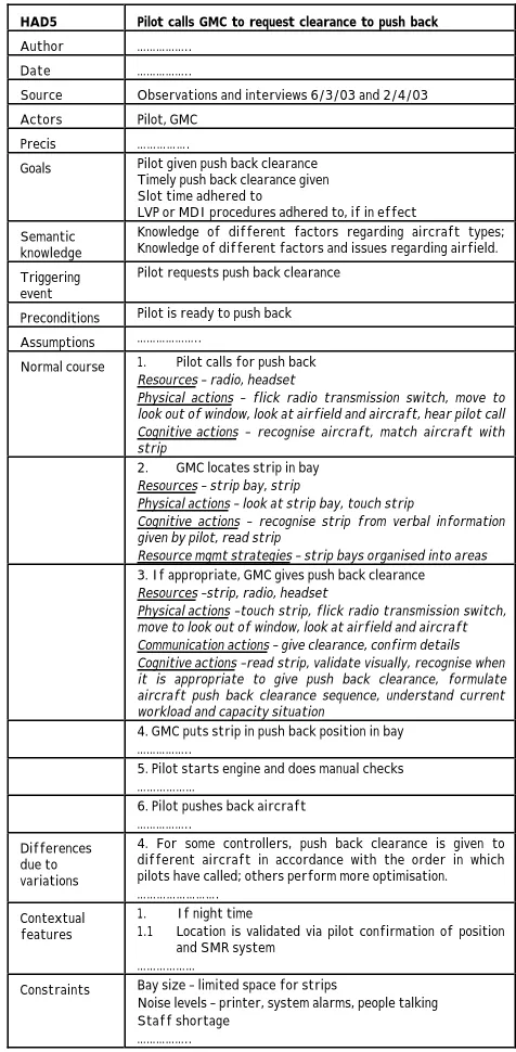
Data relating to all of the above aspects of the current work to be supported is structured into human activity descriptions such as the one presented in figure 2. As can be seen from the figure, the human activity description template provides place holders for each of the types of information identified above. It has been designed in a
similar way to our use case description template (shown in figure 4 below) in which we describe the desired behaviour of the future system. This means that information about how work is currently done can be used quite easily to help develop and check proposals for the future system to support that work.
HAD5 Pilot calls GMC to request clearance to push back
Author ……….. Date ………..
Source Observations and interviews 6/3/03 and 2/4/03 Actors Pilot, GMC
Precis ……….
Goals Pilot given push back clearance Timely push back clearance given Slot time adhered to
LVP or MDI procedures adhered to, if in effect Semantic
knowledge
Knowledge of different factors regarding aircraft types; Knowledge of different factors and issues regarding airfield. Triggering
event
Pilot requests push back clearance
Preconditions Pilot is ready to push back Assumptions ………..
Normal course 1. Pilot calls for push back Resources – radio, headset
Physical actions – flick radio transmission switch, move to look out of window, look at airfield and aircraft, hear pilot call Cognitive actions – recognise aircraft, match aircraft with strip
2. GMC locates strip in bay Resources – strip bay, strip
Physical actions – look at strip bay, touch strip
Cognitive actions – recognise strip from verbal information given by pilot, read strip
Resource mgmt strategies – strip bays organised into areas 3. If appropriate, GMC gives push back clearance Resources –strip, radio, headset
Physical actions –touch strip, flick radio transmission switch, move to look out of window, look at airfield and aircraft Communication actions – give clearance, confirm details Cognitive actions –read strip, validate visually, recognise when it is appropriate to give push back clearance, formulate aircraft push back clearance sequence, understand current workload and capacity situation
4. GMC puts strip in push back position in bay ………..
5. Pilot starts engine and does manual checks ………
6. Pilot pushes back aircraft ………..
Differences due to variations
4. For some controllers, push back clearance is given to different aircraft in accordance with the order in which pilots have called; others perform more optimisation. ……….
Contextual features
1. If night time
1.1 Location is validated via pilot confirmation of position and SMR system
………
Constraints Bay size – limited space for strips
Noise levels – printer, system alarms, people talking Staff shortage
[image:5.596.311.549.172.657.2]………..
Figure 2 shows extracts from one of the HADs developed for the DMAN project. It describes what happens when a pilot calls one of the air traffic controllers, the GMC (Ground Movement Controller), to request clearance to push back, or leave the stand ready for take-off.
Different parts of the description relate to the activity as a whole or to particular actions, thus providing a structured but flexible description of current work practices. For example, actors, goals, contextual features and constraints relate to the activity as a whole, while different resources and resource management strategies may relate to different actions.
Note also that actions in the normal course of the human activity description are broken down into their physical, cognitive, and communicative components. This information is used in generating scenarios to walk through in the use case modelling stream - see Maiden (2004) for more information.
For DMAN, the major effort of producing the HAM involved one full-time worker approximately 6 weeks. The human activity model for DMAN consisted of 15 separate human activity descriptions, each involving between 1 and 7 actors, and where the normal course contained between 5 and 12 actions.
Activity models developed in this way provide important sources of data for the development of use case models and use case authoring, as described in the following section.
3.2
Using Human Activity Descriptions to Write
Use Case Descriptions
It was envisaged that the introduction of DMAN would affect some activities in the domain more than others. For those activities where the course of events would remain essentially unchanged after the introduction of DMAN, the HADs could be used quite directly in writing use case descriptions (UCDs) for the future system.
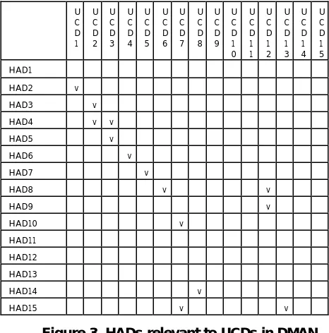
Figure 3 shows where HADs had a direct relationship to UCDs for DMAN. HAD1 (‘receive and prepare flight strip’), HAD11 (‘departure/air controller gives take off clearance’) and HAD 12 (‘flight strip logging’) do not correspond directly to any UCDs as these are activities in which DMAN will not play any role. On the other hand, it is interesting to note that much of the human activity described in HAD8 (‘departure/air controller calculates departure sequence’) and HAD9 (‘optimisation sequence’) is to be taken over by the DMAN system.
According to feedback from the engineer responsible for writing the UCDs, the HADs were most useful in writing UCDs involving sequences of prescribed behaviours, for example in interactions between pilots and controllers. U C D 1 U C D 2 U C D 3 U C D 4 U C D 5 U C D 6 U C D 7 U C D 8 U C D 9 U C D 1 0 U C D 1 1 U C D 1 2 U C D 1 3 U C D 1 4 U C D 1 5 HAD1 HAD2 v HAD3 v
HAD4 v v
HAD5 v
HAD6 v
HAD7 v
HAD8 v v
HAD9 v HAD10 v HAD11 HAD12 HAD13 HAD14 v
[image:6.596.314.547.146.382.2]HAD15 v v
Figure 3. HADs relevant to UCDs in DMAN
The list of actors in the HADs were used to check that a complete set of actors had been included in the relevant UCDs. Variations identified in HADs were also useful in identifying variations which needed to be specified in UCDs. However, information about resources was considered less useful as the resources available once DMAN was introduced would be different. The engineer did not make significant use of goals, resource management strategies, contextual features or constraints in writing UCDs.
Figure 4. Part of a DMAN Use Case Description
3.3 Using HADs to Check Other Models
At the end of each stage in RESCUE, we apply a number of ‘synchronisation checks’ to ensure that models developed in different streams remain consistent, and work done in the activity modelling and system goal modelling streams is fed through effectively into the specification of use cases, and hence requirements .
In this section, we focus on checks where the human activity model is used to validate i* models (developed in the system goal modelling stream) and use case descriptions.
At Stage 1, the relevant checks are:
At Stage 2, most cross checking is done in order to bring the human activity and first-cut i* models to bear on the development of correct and complete use case descriptions. Relevant checks are:
In DMAN, synchronisation with the human activity model was verified using checks 1.1, 1.2 and 2.2. Check 2.1 was not applied in DMAN due to lack of resources. Check 2.3 was carried out at a later stage in the project as a strategic decision was made to delay entering requirements into the requirements database until stage 4 of the process.
Check 1.1 revealed 3 current human activities that were not included in a DMAN use case – subsequent analysis revealed that these activities were not part of the DMAN socio-technical system, and no model changes were needed, and the rationale for this was documented. Likewise, check 1.3 revealed that 4 human actor roles missing from the context model were no longer roles in the new DMAN system, and no changes were made to the model.
Check 2.2 was applied on an ongoing basis, throughout stage 2 of the process, as the engineer who had been responsible for writing the HADs checked UCDs written by another engineer. Numerous issues were identified. For example, comparing HAD2 with UCD1, it was noted that some actions involved in communications between pilots and ATCOs had been omitted, and comparing HAD7 with UCD5, it was noted that the actions of transfering a flight strip to the next controller and advising a pilot of the next radio frequency to use had been omitted. At the end of stage 2, check 2.2 was applied
UCD3 Give push back clearance
Author ……….. Date ……….. Source RESCUE stage 1 Actors Pilot, Ground ATCO
Problem statement Need to improve the way in which clearances to push back from the stand are given to assist runway sequencing ….. Precis ……….
………….. ……….
Triggering event Pilot requests push back clearance Preconditions
Assumptions ……….. ………
Normal course 1. The Pilot calls the Ground ATCO and requests push back 2. The Ground ATCO looks for the flight info on the DMAN display
3. The Ground ATCO checks that the status of the flight in DMAN is ‘OK to push’
4. The Ground ATCO looks at the aircraft and nearby traffic
5. The Ground ATCO decides that the flight can push back 6. The Ground ATCO gives the push back clearance to the pilot
7. The pilot acknowledge the clearance
8. The Ground ATCO checks that the readback is correct 9. The Ground ATCO enters ‘pushback given’ to DMAN by touching an area on the electronic strip
10. DMAN records the time of push back clearance and updates the status of the flight to ‘Cleared to Pushback’ 11. The Pilot initiates push back
………..
Variation 1 If the aircraft is calling too early for its slot, then replace step 3 with:
3.1 The Ground ATCO sees that the status of the flight in DMAN is not ‘OK to push’
3.2 The Ground ATCO assesses the situation regarding workload and aircraft already remote holding
…………..
Check 1.1 Every major human activity is a candidate for one
or more use cases in the use case model.
Check 1.2 Every actor identified in human activity modelling
is a candidate actor for the context model (developed in the system goal modelling stream).
Check 2.1 Actors, resources, goals, actions and resource
management strategies identified in activity
modelling should be represented in the i* SD and
SR models as appropriate.
Check 2.2 Actors, resources, goals, actions, differences due
to variations, and differences due to contextual features in the activity models should appear in relevant use case descriptions.
Check 2.3 Goals identified in the activity models should be
with respect to the completed use case descriptions, and one further issue arose. The activity model revealed the importance of removing flights completely from the departure sequence – activities without responding use cases and actions in the use case description. The issue led to a pending change to the use case model.
4. Discussion
In RESCUE we have been able to integrate HCI concepts and techniques into a concurrent requirements engineering process in a number of different ways. Some parts of the RESCUE process, which draw on HCI process and practice in various ways are presented in more detail elsewhere. For example parallels with techniques such as those used in participatory design may be identified in our creativity workshops [6], and the way in which knowledge from HCI and cognitive psychology is used in generating and walking through scenarios to identify requirements is described in [5]. We note some commonalities between the RESCUE process, and the usage-centred design approach described by Constantine et al [1], and share the view expressed in that paper that integration of HCI with established software engineering techniques is relatively unproblematic in this case.
In this paper we have focused on the use of a model of current human activity to inform specification of a future system. We have looked in particular at the way in which human activity descriptions, written using a specially designed template, can facilitate the authoring of use case descriptions to be used in requirements elicitation. In developing our template, we aimed to address the lack of integration of techniques from cognitive task analysis and work domain analysis identified by practitioners in those fields [12], [14], and at the same time to provide better support for practicing requirements and systems engineers in specifying complex socio-technical systems.
Our human activity description template has been used successfully within the DMAN project. The Eurocontrol customer for the project was particularly impressed by the Human Activity Model and thought it was a helpful way to present current tasks, giving him a good way in to understanding descriptions of the future system. The engineer responsible for generating a specification of the future system also found human activity descriptions useful in writing and checking use case descriptions, as described earlier in the paper. Even where elements of the human activity descriptions were not used directly, we believe that the development of the human activity model gave the requirements team a better
understanding of the work and application domains, which is essential for effective requirements acquisition.
Following our experience on the DMAN project, we have some thoughts regarding the way in which benefits from this work may be increased in future projects.
Firstly, it was suggested that we might, in future, think of providing some way of structuring the HADs within the HAM, to enable the HAM reader to get an overview of the whole model, as well as a detailed view of each HAD. Mechanisms from use case modelling could be used here – for example, providing a ‘human activity diagram’ analogous to a use case diagram, to give an overview of what actors are involved in which key activities, or using the ‘include’ mechanism to avoid repetition where different HADs involve some similar lower level sequences of actions.
Feedback from the engineer who specified the use case descriptions also suggested that future projects should target the production of human activity descriptions more carefully at the areas of current functionality most likely to be directly affected by the introduction of the new system. For example, in the case of DMAN, it would have been helpful to have more detail in the human activity model about the way in which controllers handle their strips – a part of their work which will be strongly influenced by the introduction of DMAN -and less on how they use the radio – a part of the current socio-techjnical system which will not be greatly affected by the introduction of DMAN.
There is also an issue regarding the scale of effort required to produce a complete HAM. In DMAN, effort was focused on discovering what happens in a single control tower, in the key sequence of activities into which the future DMAN system would be integrated. For a system to be used in more than one location, the HAM would ideally be broader - drawing from observations in a range of locations, and going into more detail for some activities of particular relevance. However, it was not clear to the project manager that the benefits of doing this would outweigh the costs.
disciplines. In future projects, we would begin with more training in this area, to give engineers greater confidence in recording and using data relating to each of these concepts. We would also suggest that use case descriptions should be written in a more collaborative manner with inputs from engineers with experience in both requirements engineering and HCI.
This leads us to our final point: the need for multi-disciplinary requirements and design teams. On the basis of our experience, we argue that those involved in the development of socio-technical systems must stop thinking in terms of the narrow disciplines of software engineering or HCI, but rather in terms of a broader discipline researching the design and engineering of socio-technical systems, in which work design, interaction design and software design are all interdependent.
In addition, collaboration between members of such a multi-disciplinary team must be facilitated by the use of design artefacts which all can comprehend. On the basis of our experience in DMAN, we believe that human activity models, comprising human activity descriptions written using the template presented in this paper can provide this kind of support. Use cases and scenarios are now very commonly used in requirements engineering practice - Neill and Laplante [9] report that they are used for requirements elicitation in over 50% of projects. Our work aims specifically to provide a way of dovetailing a range of HCI concerns with current best practice in use case authoring. We are therefore optimistic that our work might provide a useful basis for increasing collaboration between those from backgrounds in HCI and requirements or systems engineering in the specification of requirements for socio-technical systems.
5.
Acknowledgements
The authors wish to thank all members of the DMAN project team for their participation and support throughout the project, and all those at NATS, Sofreavia and Eurocontrol who have contributed to the development of the RESCUE process as a whole.
6.
References
[1] Constantine L, Biddle R. and Noble J., “Usage-Centred Design and Software Engineering: Models for Integration”, in Bridging the Gaps between Software Engineering and Human-Computer Interaction, IEEE CS Press, 2003.
[2] Diaper D (ed), Task Analysis for Human-Computer Interaction, Ellis-Horwood, 1989.
[3] Dix A, Finlay J, Abowd G and Beale R, Human-Computer Interaction, 2nd edition, Prentice Hall, 1997.
[4] ICAO, ‘Human Factors in CNS/ATM systems. The development of human-centred automation and advanced technology in future aviation systems’ ICAO Circular 249-AN/149, 1994.
[5] Maiden N, “Systematic Scenario Walkthroughs with ART-SCENE”, to appear in Alexander I & Maiden N (eds), ‘Scenarios in Practice’, John Wiley, 2004.
[6] Maiden N, Manning S, Robertson S and Greenwood J, “Integrating Creativity Workshops into Structured Requirements Processes”, to appear in Proc DIS2004, 2004.
[7] Maiden N. and Gizikis A, “Where Do Requirements Come From?”, IEEE Software, Sept/Oct, 18(4), 10-12, 2001.
[8] Maiden N, and Rugg G, “ACRE: Selecting Methods For Requirements Acquisition”, Software Engineering Journal 11(3), 183-192, 1996.
[9] Neill C and Laplante P, “Requirements Engineering: The State of the Practice,” IEEE Software, Nov/Dec, 40–45, 2003.
[10] Paech B and Kohler K “Usability Engineering integrated with Requirements Engineering”, in Bridging the Gaps between Software Engineering and Human-Computer Interaction, IEEE CS Press, 2003.
[11] Robertson S. and Robertson J, Mastering the Requirements Process, Addison-Wesley-Longman, 1999.
[12] Schraagen J, Ruisseau J, Graff N, Annett J, Strub M, Sheppard C, Chipman S, Shalin V and Shute V, “Cognitive Task Analysis”, RTO Technical Report 24, North Atlantic Treaty Organisation, 2000.
[13] Sutcliffe A, Maiden N, Minocha S, Manuel D, “Supporting Scenario-Based Requirements Engineering”, IEEE Trans Software Engineering, 24(12), 1072-1088, 1998.
[14] Vicente, K., Cognitive Work Analysis, Lawrence Erlbaum Associates, 1999