D
etection
F
or
D
s
-
cdma
W
ireless
N
etworks
A thesis submitted for the degree of Doctor of Philosophy of The Australian National University
Peter Koon Pong Cheung
B.E. (Hon. 1), University of Queensland, Australia.
Telecommunications Engineering Group
Research School of Information Sciences and Engineering The Australian National University
The contents of this thesis are the result of original research and have not been submitted for a higher degree to any other university or institution.
Much of the work presented in this thesis has been published or will be sub mitted for publication as journal or conference papers. Following is a list of these papers. In some cases, the conference papers contain material overlapping with the journal papers.
J o u rn a l P a p ers
• P.K.P.Cheung and R.A.Kennedy, “Robust Blind Adaptive Detection for Synchronous Multiuser CDMA Systems,” submitted for IEE Proc. Com- mun., Aug. 1997.
• P.K.P.Cheung and P.B.Rapajic, “CMA-based Code Acquisition Scheme for DS-CDMA Systems,” submitted for IEEE Trans. Commun., (subject to revision), Oct. 1997.
• P.K.P.Cheung, P.B.Rapajic, R.A.Kennedy and I.Fijalkow, “Blind Multiuser Multiple Sensor Receiver for DS-CDMA Systems over Frequency Selec tive Multipath Channels,” submitted for IEEE J. Selected Areas Commun., Sept. 1998.
C o n feren ce P a p e r s
• P.K.P.Cheung, R.A.Kennedy, “Improved Blind Adaptive Detection for Syn chronous Multiuser CDMA Systems,” in Proc. IEEE Workshop on Signal Processing Adv. in Wireless Commun., pp.249-252, Paris, France, 16-18 Apr. 1997.
• P.K.P.Cheung and P.B.Rapajic, “Blind Adaptive Code Acquisition for Mul tiuser DS-CDMA Systems,” in Proc. IEEE Personal, Indoor, Mobile Radio
Conf., pp.337-341, Helsinki, Finland, 1-4 Sept. 1997.
• P.K.P.Cheung, P.B.Rapajic and R. A.Kennedy, “Effect of new users on blind adaptive synchronous multiuser DS-CDMA detection,” in Proc. IEEE Int. Conf. on Commun., Atlanta, USA, 7-11 Jun. 1998.
• P.K.P.Cheung and P.B.Rapajic, “CMA-based Blind adaptive detection for Synchronous DS-CDMA systems over Frequency-selective Channels,” in Proc. IEEE Int. Symp. on Inf. Theory, p.184, Cambridge, USA, 16-21 Aug. 1998.
Most of research presented in this thesis has been performed jointly with Dr Rodney A. Kennedy and Dr Predrag B. Rapajic. The work related to con strained CMA-based receiver in Chapter 5 was done in collaboration with Dr Inbar Fijalkow (Equipe de Traitement des Images et des Signaux (ETIS), Ecole Nationale Superieure de l’Electronique et de ses Applications (ENSEA) - Uni versity de Cergy-Pontoise, France). However, the majority of the work, approxi mately 90%, was my own.
My Ph.D. would not have been possible without the support of the following people and organisations.
First and foremost, I am thankful to my family, the most caring people for supporting me for the past twenty-five years. From day one, both of my parents and all of my brothers Ben, Eddie and David have always stood by me. T would never thank my family enough for their continuous encouragement, especially during those times when I was truly down and out. Although I have been a problem child all my life, my family has always been patient and caring.
My supervisors Dr Rod Kennedy and Dr Predrag Rapajic deserve many thanks for their guidance and insight. Special thanks to Rod for his help in my enrolment and scholarship applications, overseas and interstate trips, and career advice. As for Predrag, I am particularly impressed with his own (dry) humour and drawings, during those countless visits to his office.
I would like to thank Dr Inbar Fijalkow (Universitee de Cergy-Pontoise, France) for many useful discussion and comments regarding the CM A, during those final months of my Ph.D.
My gratitude to Dr Brian Hart and Dr Lei Wei for their tuitions on many important topics. Of course, thanks must go to both Rod and Brian for their readiness in running the Canberra fun run and the City-to-Surf race.
My thanks to the departmental visitor Mr Julio Castro (New Mexico State University) for proof-reading my thesis, during the final few months of my Ph.D.
For the opportunity to visit Cornell University, I thank Mr Raul Casas and Prof. Rick Johnson (also Phil Schniter for his advice). In particular, many thanks to Raul for putting me up during the visit and his helpful tuitions during the early months of my Ph.D. Also, I would like to thank Dr Miro Kraetzl and Dr Langford White for the visit to Defence Science and Technology Organization (DSTO) in Salisbury, South Australia.
A big “thank you” to all my friends in Canberra, interstate and overseas. In particular, my appreciation to Allen (thanks Allen for his 10-years long loyalty and friendship), Geoff (thanks Geoff for reading my thesis draft and his many encouragement) and Tim (thanks Tim for putting me up in Sydney) who have never lost faith in me and have never failed to show. Thanks to my friends in Ursula College who have seen my best and worst. In particular, I am deeply indebted to Mel for her continuous counsel to keep me from going insane. Also, special thanks to Luciana in Hong Kong for those never-ending well wishes and supports she gave me from her letters.
As business and domestic activities become globalised, wireless telecommunica tion must be able to provide mobile communications “anywhere” and “anytime”. The Code Division Multiple Access (CDMA) technology has been proposed to implement the future wireless communication systems, mainly due to its promise of capacity improvement over the traditional multiple access schemes based on non-overlapping frequency bands or time slots. Since the same channel resource is shared by all users, signals from other users would appear as Multiple Access Interference (MAI) to the signal of interest. Unlike the conventional Matched Filter (MF) approach, multiuser detection does not treat MAI as structure-less Gaussian noise. This thesis considers the problem of “blind” adaptive linear mul tiuser detection for Direct Sequence (DS) - CDMA systems. The blind terminol ogy means that the receiver has only the knowledge of the transmitted signature waveform of the desired user, and training data is not available.
For a synchronous DS-CDMA without multipath channels, two new blind detectors, one based on a constrained Minimum Output Energy (MOE) and one based on the Constant Modulus Algorithm (CMA), have been proposed as robust alternatives to the popular MOE detector. It is shown that the CMA-based detector exhibits a desirable lock convergence property which in the absence of channel noise, nulls all interferers. Unlike the CMA-based single-user channel equaliser, robust initialisation for lock convergence is possible.
mul-tiuser detection, it fully exploits the benefits of multiple sensors. It highlights the limitations of using MF based beamforming in multiuser detection. The pro posed second detector is based on the constrained inverse filtering approach which forces the multipath induced interference to be zero. Under some general condi tions, lock convergence is always ensured for the constrained CMA in the second method, regardless of its initialisation. Also, the constrained CMA is modified to blindly acquire the timing delay of the desired user. The idea is that lock con vergence should only occur for the filter associated with the correct hypothesised delay.
D e c la r a tio n iii
A c k n o w le d g e m e n ts v
A b s tr a c t v ii
G lo ssa r y x v
1 I n tr o d u c tio n 1
1.1 B ack g ro u n d ... 1
1.1.1 Concepts of Wireless Personal Communication Systems . . 1
1.1.2 Basic Cellular System ... 3
1.1.3 Multiple Access T ec h n iq u e s... 5
1.1.4 Application of CDMA in P C S ... 9
1.2 Practical PCS S ta n d ard s... 11
1.2.1 First Generation ... 11
1.2.2 Second G e n e ra tio n ... 13
1.2.3 Third G eneration... 15
1.3 Thesis Overview... 15
1.4 Thesis Contribution... 19
2 O v e r v ie w o f M u ltiu se r D e te c tio n 21 2.1 Chapter O u tlin e... 21
2.2 Two Approaches in CDMA System D e sig n ... 21
2.3.1 System Configuration... 25
2.3.2 T ra n s m itte r... 26
2.3.3 C h a n n e l... 28
2.3.4 R eceiv er... 33
2.3.5 List of General A ssum ptions... 35
2.4 Background of Multiuser D e te c tio n ... 38
2.4.1 Problem Statement of Multiuser D e te c tio n ... 38
2.4.2 L im ita tio n s ... 39
2.4.3 Potential B enefits... 40
2.4.4 Concept of Blind Multiuser D etection... 40
2.5 Literature Review of Multiuser D etection... 41
2.5.1 Synchronous DS-CDMA Signal Model ... 42
2.5.2 Asynchronism ... 42
2.5.3 Conventional DS-CDMA d e te c to r ... 43
2.5.4 Optimum Multiuser D etectio n ... 45
2.5.5 Linear Multiuser Detection... 46
2.5.6 Non-Linear Multiuser D e tectio n ... 48
2.5.7 Adaptive Multiuser D e te c tio n ... 49
2.5.8 Blind Multiuser D e te c tio n ... 51
2.6 Chapter S u m m a r y ... 56
3 T w o B lin d L in ea r M u ltiu se r D e te c to r s — M in im u m O u tp u t E n e r g y (M O E ) an d C o n sta n t M o d u lu s A lg o r ith m (C M A ) 57 3.1 Chapter O u tlin e... 57
3.2 System M odelling... 58
3.3 Review of MOE D etector... 58
3.3.1 Canonical Representation of Linear Multiuser Detectors . . 59
3.3.2 MOE Detector ... 60
3.3.3 Benefits of MOE D e te c to r ... 60
3.3.4 Weaknesses of MOE D e te c to r ... 61
3.4 Robust Alternative to M O E ... 63
3.5 Steady State Behaviour... 65
3.5.1 Lock and Capture Analysis of C M A ... 66
3.5.2 Capture A voidance... 67
3.5.3 Global Convergence of M O E ... 71
3.6 Transient Behaviour ... 72
3.6.1 Convergence Rate of C M A ... 72
3.6.2 Convergence Rate of M O E ... 76
3.7 Signature Mismatch Problem ... 78
3.7.1 Constrained Surplus E n e rg y ... 78
3.7.2 Selection of Linear C o n s tra in t... 78
3.8 Simulation R e s u l ts ... 80
3.8.1 System P a ra m e te rs... 80
3.8.2 Performance M e a s u re s ... 80
3.8.3 Discussion... 81
3.9 C onclusions... 85
4 C M A -b a se d R A K E -ty p e R e c e iv e r 87 4.1 Chapter O utline... 87
4.2 Literature Review ... 88
4.3 Space-Time P rocessing... 89
4.3.1 Concept of Receiver D iv e rs ity ... 89
4.3.2 2-D RAKE R e c e iv e r ... 90
4.4 System M odelling... 92
4.4.1 Channel M o d e l... 92
4.4.2 Received Signal M o d e l... 93
4.5 Receiver Structure ... 94
4.5.1 B e n e fits ... 95
4.5.2 Windowed Chip Rate S a m p lin g ... 95
4.5.3 Generalisation to Multiple Sensors ... 97
4.5.5 Linear Diversity C om biner... 99
4.6 CMA-based Adaptation ...100
4.6.1 O b je c tiv e ...100
4.6.2 A lg o rith m ...100
4.7 Analysis of CMA-based RAKE-type Receiver ...101
4.7.1 Lock and Capture Analysis ... 101
4.7.2 Robust In itia lis a tio n ... 103
4.7.3 Convergence R a te ... 104
4.7.4 Channel Order M ism atch... 105
4.8 Simulation R e s u l t s ...106
4.8.1 System P a ra m e te rs... 106
4.8.2 Performance M e a s u re s... 106
4.8.3 Comparison to Other Multiuser D e te c to r s ...107
4.8.4 D iscussion...109
4.9 C o n clu sio n s... 114
5 C o n s tr a in e d C M A -b a se d R e c e iv e r 115 5.1 Chapter O u tlin e...115
5.2 System M o d e l... 116
5.2.1 Model Assum ptions... 116
5.2.2 Received Signal M o d e l... 116
5.3 Inverse Filtering C r ite r io n ...119
5.3.1 Decorrelating D e te c to r... 120
5.3.2 MMSE D etector...120
5.4 Constrained CMA A pproach... 120
5.4.1 Constrained P aram eterisatio n ... 121
5.4.2 Constrained CMA A d ap tatio n ... 123
5.5 Convergence A nalysis...123
5.5.1 Stationary P o in ts ...124
5.5.2 Stability of Class 1 ...126
5.5.3 Stationary Points in Class 2 ... 127
5.6.3 D iscussion...131
5.7 C onclusions...134
6 E ffe c t o f A rriv a l o f A d d itio n a l U se r s 135 6.1 Chapter O utline... 135
6.2 M otivation... 136
6.3 Literature R eview ...136
6.4 System M odelling...138
6.4.1 Signal M o d e l ...138
6.4.2 Robustness in terms of User Gains ...139
6.5 Change in the CM, MSE and MOE Costs ...140
6.5.1 CM C o s t...140
6.5.2 MSE C o s t ...142
6.5.3 MOE C o s t... 143
6.5.4 Comparison of CM, MSE and MOE co sts...144
6.6 Simulation R e s u l t s ... 144
6.6.1 System Parameters and Performance M easures... 145
6.6.2 D iscussion...145
6.7 C on clu sio n s... 148
7 C o n str a in e d C M A -b a sed C o d e A c q u is itio n S c h e m e 149 7.1 Chapter O u tlin e...149
7.2 B ack g ro u n d ... 150
7.3 System M odelling...151
7.3.1 Discrete-Time Received Signal M o d e l...151
7.3.2 Equivalent Synchronous Model . ... 152
7.4 Literature R eview ...154
7.5 CMA-based Code Acquisition Scheme... 156
7.5.1 Problem statement of Code A cquisition...157
7.5.3 Convergence Analysis of Constrained C M A ... 159
7.5.4 Two Decision Variables: Decorrelation and Average Out put Energy C riteria...162
7.6 Simulation R e s u l t s ... 164
7.6.1 Other Acquisition Methods ... 164
7.6.2 Simulation Parameters and Performance M e a s u re ... 166
7.6.3 D iscussion... 167
7.7 C onclusions... 169
8 C o n c lu sio n s and F u tu re R e se a rc h D ir e c tio n s 175 8.1 C onclusions... 175
8.2 Future Research Directions...177
A S ta tio n a r y P o in ts o f C M A 179
eaMTfttb
PhD Thesis
ex*M«\ets! R&fozh
...
A b b r e v ia tio n s
AM PS Advanced Mobile Phone System
AWGN A dditive W hite G aussian Noise
B E R B it Error R ate
B P F Bandpass Filter
B PSK B inary Phase Shift Keying
CDMA Code Division M ultiple Access
CM C onstant Modulus
CM A C onstant M odulus A lgorithm
conv. convolutional
CSMA C arrier Sense M ultiple Access
CT-2 Second G eneration Cordless Telecom munications
dB decibel
DD Decision D irected
D E C T D igital European Cordless Telecom m unications
D Q PSK Differential Q u ad ratu re Phase Shift Keying
DS D irect Sequence
EM estim atio n /m ax isatio n
ESN Electronic Serial N um ber
FDD Frequency Division Duplex
FD M A Frequency Division M ultiple Access
FH Frequency Hopping
F M F re q u e n c y M o d u la tio n
F P L M T S F u tu r e P u b lic L a n d M o b ile T e le c o m m u n ic a tio n s S y s te m s
G M S K G a u s sia n M in im u m S h ift K e y in g
G SM G lo b a l S y s te m fo r M o b ile c o m m u n ic a tio n
H O S H ig h e r O rd e r S ta tis tic s
IC I In te r-C h ip -In te rfe re n c e
IM T -2 0 0 0 I n te r n a tio n a l M o b ile T e le c o m m u n ic a tio n
IS I n te r im S ta n d a r d
ISI In te r-S y m b o l-In te rfe re n c e
IT U I n te r n a tio n a l T e le c o m m u n ic a tio n U n io n
LM S L e a st M ean S q u a re s
LO S L in e-o f-S ig ht
L P C L in e a r P r e d ic tiv e C o d e
L P F Low pass F ilte r
L T I Li n e a r-T i m e -In v a ria n t
M A M u ltip le A ccess
M A I M u ltip le A ccess In te rfe re n c e
M B S M o b ile B r o a d b a n d S y s te m s
M C M u lti-C a rrie r
M F M a tc h e d F ilte r
M IM O M u ltip le - I n p u t M u ltip le - O u tp u t
M L M a x im u m L ik elih o o d
M L S E M a x im u m L ik elih o o d S e q u e n c e E s tim a tio n
M M S E M in im u m M e a n S q u a re d E rro r
M O E M in im u m O u tp u t E n e rg y
M S E M e a n S q u a re d E r r o r
M T S O M o b ile T e le p h o n e S w itc h in g O ffice
M U S IC M u lti p le S ig n a l C la ssific a tio n
N A N o rth A m e ric a n
N B I N a rro w b a n d In te rfe re n c e
P A C S P e rs o n a l A ccess C o m m u n ic a tio n s S y s te m
P C S P e rs o n a l C o m m u n ic a tio n s S y s te m s
P D C P e rs o n a l D ig ita l C e llu la r
p .d .f. p ro b a b ility d e n s ity f u n c tio n
P H S P e rs o n a l H a n d y p h o n e S y s te m
P N P se u d o -N o ise
P R M A P a c k e t R e s e rv a tio n M u ltip le A ccess
P S K P h a s e S h ift K ey in g
P S T N P u b lic S w itc h in g T e le p h o n e N e tw o rk
Q C E L P Q u a lc o m m C o d e E x c ite d L in e a r P re d ic tiv e
R L S R e c u rs iv e L e a st S q u ares
R P E R e g u la r P u ls e E x c ita tio n
S D M A S p a c e D ivisio n M u ltip le A ccess
S IR S ig n a l-to -In te rfe re n c e R a tio
S N R S ig n a l-to -N o ise R a tio
S O S S e c o n d O rd e r S ta tis tic s
s td . s ta n d a r d
T A C S T o ta l A ccess C o m m u n ic a tio n s S y s te m
T D D T im e D iv isio n D u p lex
T D M A T im e D ivisio n M u ltip le A ccess
T H T im e H o p p in g
U M T S U n iv e rs a l M o b ile T e le c o m m u n ic a tio n s S y s te m
VA V ite rb i A lg o rith m
V S E L P V e c to r S u m E x c ite d L in e a r P re d ic tiv e
N o ta tio n s
(,)T M a tr ix o r v e c to r tra n s p o s e
I ' l M o d u lu s o f a sc a la r
II ' l l 2 -n o rm o f a v e c to r
r a n k ( - ) R a n k o f a m a tr ix * C o n v o lu tio n o p e ra to r
(•)* C o m p le x c o n ju g a tio n
L - J F lo o r o p e r a to r
«(•) D ira c d e lta fu n c tio n
De c(-) D ecisio n d ev ice o p e ra to r
s g n ( - ) S ig n u m fu n c tio n
Re(-)
R e a l p a r t o f a co m p le x sc a la rn
S et o f re a l n u m b e rsl x ( X x X )-s iz e id e n tity m a tr ix
( X ) n , m T h e ( n ,m ) - t h c o m p o n e n t o f m a tr ix X
V XQ D e riv a tiv e o f Q w ith re s p e c t to x
diagCX.) M a tr ix e x tr a c te d fro m X w ith th e sa m e d ia g o n al e n trie s , a n d 0 e lsew h ere
h (X ) T h e &th eig en v alu e o f X X t P se u d o -in v e rs e o f X
t r a c e ( X . ) T ra c e o f th e sq u a re m a tr ix X
1.1 Overview of a cellular system... 4 1.2 Classification of the Multiple Access techniques [1]... 6 2.1 A block diagram of an asynchronous TT-user DS-CDMA system
with generalised multiuser detection... 25 2.2 A block diagram of DS-CDMA transmitter for the kth user. . . . 27 2.3 Illustration of a typical mobile radio environment... 28 2.4 Tapped delay line model of a DS-CDMA frequency selective chan
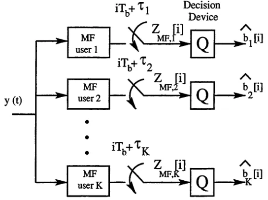
nel for the kth. user... 31 2.5 A block diagram of DS-CDMA receiver with generalised multiuser
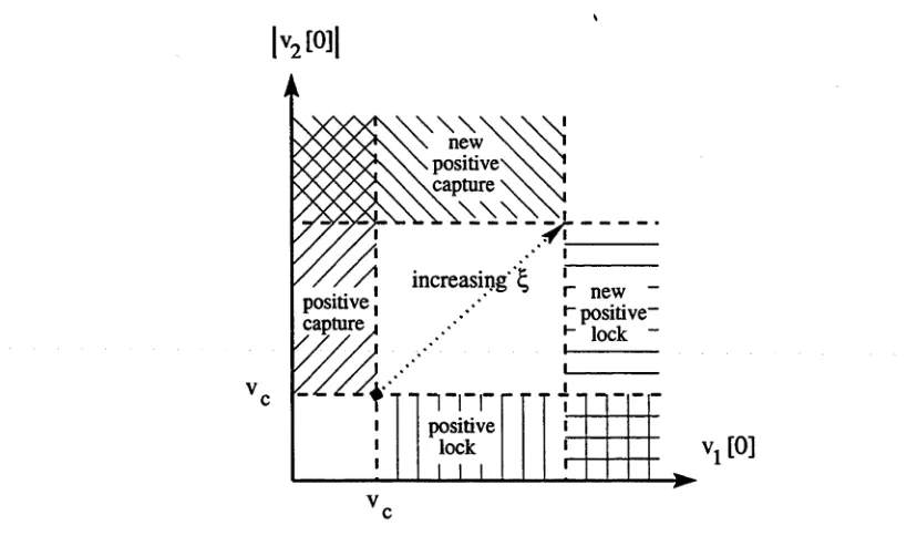
detection for user 1 [2]... 34 2.6 The conventional DS-CDMA detector: a bank of MFs... 44 3.1 The canonical representation of a linear multiuser detector [3] . . 59 3.2 Capture avoidance of the CMA by scaling the received signal by v. 69 3.3 Capture avoidance of the CMA by increasing the modulus radius f . 69 3.4 Region of annulus S that contains all CM local minima and saddle
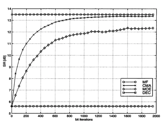
points [4]... 75 3.5 Filter constraint to avoid the complete desired signal cancellation. 79 3.6 The transient SIR for different multiuser detectors: K = 10, N F R =
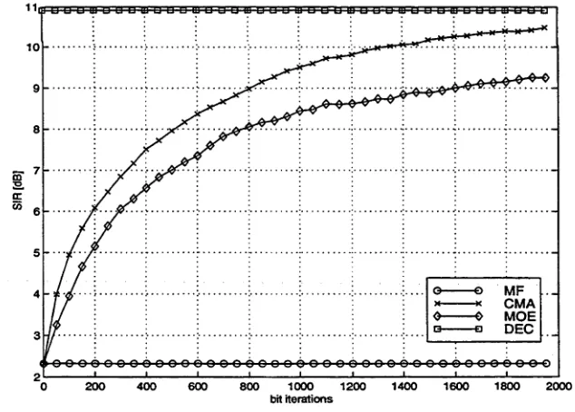
0dB, S N R ( k = 1) = 12d B... 82 3.7 The transient SIR for different multiuser detectors with near far
condition: K = 10, N F R = 6d£, S N R ( k = 1) = 12d B... 83 3.8 The transient SIR for different multiuser detectors with increased
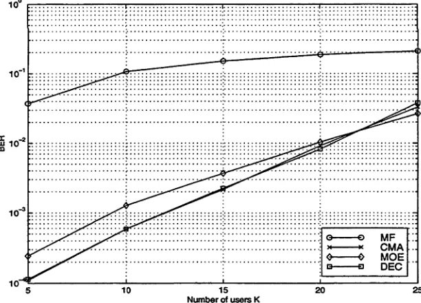
3.9 The steady state BER vs. S N R ( k = 1) for different multiuser detectors: K = 10 and N F R = 3d B... 84 3.10 The steady state BER vs. K for different multiuser detectors:
S N R { k = 1) = 9dB and N F R = 3d B... 84 3.11 The steady state BER vs. N F R for different multiuser detectors:
K = 10, S N R ( k = 1) = 10d B... 85 4.1 Structure of the proposed blind multiuser multiple sensor receiver. 94 4.2 The ISI-free observation interval with the time window TC( N — L +1). 97 4.3 The transient SIR for single sensor based blind methods: M = 1,
N = 31, K = 10, SNR( k = 1) = 12dB, N F R = 3dB, L = 3. . . . I l l 4.4 The steady state BER vs. S N R ( k = 1) for single sensor based
blind methods: M = 1, N = 31, K = 10, N F R = 3dB, L = 3. . . I l l 4.5 The steady state BER vs. channel order L for single sensor based
blind methods: M = 1, N = 31, K = 5, S N R ( k = 1) = 12dB, N F R = 3dB... 112 4.6 The steady state BER vs. N F R for multiple sensors based blind
methods: N = 31, K = 10, S N R ( k = 1) = 12dB, M £ {1,2,3}, L = 3... 112 4.7 The probability of non-lock convergence initialisation vs. various
actual channel orders L a, for the single sensor based proposed re ceiver under channel undermodelling: M = \, N = 3\, K = 10, S N R ( k = 1) = 12dB, N F R £ {OdB, 3dB, 6dB}, and modelled channel order is L = 2...113 5.1 Percentage of rank = 2 K —2 vs. number of users K, using
500 Monte Carlo runs with = 31, M £ {1,3} and L £ {1,3,6,9}. 129 5.2 The transient SIR [dB] performance of the constrained CMA, con
strained MOE and MMSE detectors: N = 31, M = 1, K = 10 and S N R ( k ) = lbdB Vfc € { 2 ,... , 1 0 } ... 132 5.3 The transient SIR [dB] performance of the constrained CMA, con
and S N R = \5dB for all users... 133 6.1 The transient SIR performance of the training-based MMSE, the
CMA, the constrained MOE and the MF detectors, when there are sudden arrivals of 5 new users every 5000 bits: N F R = 6dB and S N R ( k = 1) = 10 d B...146 6.2 The transient normalised MSE performance of Figure 6.1...147 7.1 Left and right partitions of the discrete-time signature of the kth
user, in an one-shot signal model [5,6]... 153 7.2 Magnitude of converged user gains |uA;i„[is]| vs. delay hypotheses
n and user indices k using the equivalent 2A-user synchronous model: N = 31, T\ = 0 , is = 500, and S NR( k ) = 15dB Wk £
{2 170
7.3 Magnitude of converged user gains |ufc>n[z5]| vs. delay hypotheses n and user indices k using the equivalent 2A-user synchronous model: N = 31, T\ — N /2, is = 500, and SNR{k) = 15dB Vfc £
{ 2 ,... , K]... 171. 7.4 Probability of acquisition vs. NFR: N = 31, K = 10, and
S NR{ k) = !5dB Vfc£ { 2 ,... ,10}... 172 7.5 Probability of acquisition vs. N F R for the proposed method
with various filter scaling ß: N = 31, K = 10, and S N R ( k ) = 15dB VJb€{2,... ,10}...172 7.6 Probability of acquisition vs. K: N = 31, S NR( k ) = 15dB Wk £
{2,... , A}, and equal-power users ... 173 7.7 Probability of acquisition vs. K: N = 31, S NR( k ) = 15dB \/k £
In trod u ction
In this introductory chapter, background material for the wireless Personal Com munication Systems (PCS) is presented. For the purpose of illustration, some practical PCS standards are discussed. This is followed by an overview of this thesis and its contributions. The purpose of this chapter is to provide a concrete foundation of existing multiple acces techniques, and their implementations. In accordance with the focus of this thesis, emphasis is place on the application of the Code Division Multiple Access (CDMA) in PCS.
1.1
B a ck g ro u n d
1.1.1
C on cep ts o f W ireless Personal C om m unication S ys
tem s
The purpose of Personal Communications Systems (PCS) is to provide customers with wireless access to information services [8]. It has been predicted that [9] future PCS may one day replace the wireline telephone and transform the world into a global wireless network. The ultimate goal of PCS is to achieve high-speed, high-quality and secure communication, in any place, at any time, in any form, through any medium, at minimum cost, by using hand-held terminals.
Chapter 1: Introduction
unified PCS. These present PCS families are:
• M obile C om puting — this was propelled by the popularity of portable personal computers and networking. For example, wireless local area net works provide high throughput communications (Mb/s) for slowly moving terminals in a small coverage area (tens of meters).
• M obile Satellite System — this uses satellites as base stations. They provide the largest coverage (continental or global service area) but deliver the lowest bit rate services (10kb/s or less).
• Low-Tier System — this is designed to serve pedestrian users with low mobility, namely residential cordless phones. A common example of cordless telephone is the telepoint which provides an alternative to wired public tele phone systems. Also, paging is an important precursor in low-tier systems and is the simplest, cheapest PCS.
• H igh-Tier System — this is designed for high mobility, vehicle-borne users with voice and data services, namely cellular networks. It has the largest commercial impact with revenues currently growing at about 40% per year [10]. In the United States, the cellular market exceeds 15% for individuals and 30% for households [8]. The popularity of cellular service is further fuelled by the continuing advances in integrated circuit technology giving low-power micro-processors that are sufficiently powerful to permit complex call control protocols.
With the explosive growth of wireless PCS in this decade, there is the need for new technology devised to meet the technical challenges. These challenges are translated into the following figures of merit [7,8]:
• Service Quality — near-wireline voice quality, enhanced in-building pene tration, easy-to-use user interface, lower probability of call blocking, shorter setup time, ability to overcome transmission impairments (e.g., multiple fading), enhanced privacy (i.e., prevent eavesdropping), enhanced mobility, fewer dropped calls, longer talk times and lower power requirements (e.g., longer battery life).
• O perating Company — lower infrastructure and operating cost (e.g., fewer base stations), higher spectral efficiency (e.g., increase subscriber ca pacity), enhanced network security to prevent unauthorised access, early deployment and adaptability by anticipating future technology advances.
1.1.2
B asic Cellular System
Most PCSs employ some forms of cellular technology, either in cellular frequency bands or PCS bands [7,8]. Depending on government policies, regulatory agencies in different countries have allocated limited bandwidth to PCS. Hence, advanced PCS technology must achieve high spectral efficiency. In general, there are two ways to define spectral efficiency:
1. The maximum number of channels or users that can be supported per unit service area per given bandwidth (commonly known as channel capacity); 2. Erlangs1 per unit service area per given bandwidth.
For telephony, the first definition measures the maximum number of simultaneous conversations per base station per MHz, and is to be used throughout this thesis. The second measure is related to the average traffic load that a base station can handle, while meeting a specified call blocking objective.
For example, in the United States, regulators issue two cellular radio licenses in each geographical area. The resultant bandwidth allocations are 25MHz for cellular operators2, and three 30MHz plus three 10MHz allocations for wideband
Chapter 1: Introduction
microwave links or T-carriers
mobile terminal Base Station
interface
standard voice trunks
PSTN
MTSO
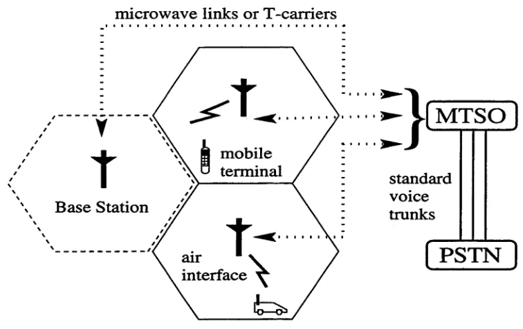
Figure 1.1: Overview of a cellular system.
PCS service. The cellular and PCS services have different frequency assignments with carrier frequencies in the vicinity of 850MHz and 1.9GHz respectively.
[image:28.525.69.447.89.327.2]Over the air interface, the assigned spectrum is split into two directions of communications: the reverse link or uplink (i.e., mobile-to-base-station), and the forward link or downlink (i.e., base-station-to-mobile). For information transfer over air interface, each mobile terminal can only use one communication channel at a time. A channel can be mathematically represented by a frequency band, a time slot or a code. Between the base station and MTSO, microwave radio links or T-carriers (i.e., wired telephone lines) are used to carry both voice and data. Finally, standard voice trunks are used to connect PSTN and MTSO.
Wireless PCSs can also be classified in terms of their transmission methods as simplex, half-duplex and full-duplex. Simplex PCSs provide one-way commu nication, and the best known example is the paging system. Half-duplex and full-duplex PCSs both allow two-way communications by using the same and different radio channel respectively. Full-duplex PCSs can be supported by Fre quency Divison Duplex (FDD) or Time Division Duplex (TDD), which represent by a pair of reverse and forward channels that are separated in different frequency bands or time slots respectively. Most existing PCSs are full-duplex using FDD, although new cordless telephones are using TDD.
W ith a call in progress, whenever the mobile terminal crosses the boundary between two cells, its communication channel is switched from one base station to another. This procedure is referred to as handoff or handover and is carried out without either interrupting the call or alerting the user. Another common scenario is roaming where a mobile terminal is operating outside its home service area. Since the early 1990s, the trend in cellular industries is to adopt open interfaces between equipments, rather than proprietary ones. As a result, equipment from different manufacturers can now be assembled together to facilitate mobility and roaming.
1.1.3
M ultiple A ccess Techniques
Chapter 1: Introduction
f Scheduling M A j f Random Access MA J [ CDMA) ( SD M A ]
DS FH TH Chirp Hybrid
TDMA
FDMA PollingToken Passing p-ALOHA Fixed
Assignment DemandAssignment RepeatedRandom Access
Random Access with Reservation
Multiple Access Techniques
CSMA etc. r-ALOHA PRMA etc.
Figure 1.2: Classification of the Multiple Access techniques [1].
scarceness of channel resource (i.e., bandwidth), MA techniques are used to share the common transmission channel among all users in the system. The MA tech nology should be robust to channel impairments and changing conditions (e.g., traffic load is not spatially nor temporally uniform); and the receiver should be able to separate the desired signal from interfering signals.
As shown in Figure 1.2, the MA techniques can be classified into four main groups as follows [1,11].
1. Scheduling M A — it avoids simultaneous access from multiple users by scheduling all transmissions. This scheduling protocol can either be imple mented as a fixed assignment where the channel capacity is divided among the users in a static fashion, or as a demand assignment where the scheduled transmission takes place only if the user is active. Unlike the fixed assign ment, the demand assignment does not waste channel capacity on idle users, albeit additional overhead and delay are introduced to sort out active users. Examples of demand assignment MA protocols include roll-call polling and token-passing [1].
[image:30.525.52.466.92.295.2]di-vide a single high-capacity MA channel into smaller orthogonal channels. This is typically done by channel partition in terms of disjoint frequency bands known as Frequency Division Multiple Access (FDMA), disjoint time slots known as Time Division Multiple Access (TDMA), or both (i.e., hy brid FDMA/TDMA). Hence, their capacities correspond to the number of channel partitions. To avoid co-channel interference (i.e., overlapping of different transmissions), guard times and bands are inserted between ad jacent transmissions in TDMA and FDMA respectively. In cellular radio
systems, to avoid co-channel interference, the concept of frequency reuse is used to place a minimum distance between cells using the same frequency set. A well-designed frequency reuse plan respects a compromise between high reception quality (i.e., low reuse factor) and high spectral efficiency (i.e., high reuse factor). Both TDMA and FDMA. provide a simple MA so lution in a steady or slowly varying traffic network. It is noted that FDMA is simpler than TDMA, since no synchronisation between users is required. 2. Random Access M A — it resolves the contention (or collision) that
occurs when several users transmit simultaneously. The first random ac cess system, known as ALOHA, was proposed for packet radio network in 1969 [12]. The family of ALOHA protocols assumes that there is the possi bility of contention with every transmission. If the contention is detected, the user can defer its own transmission until the channel is free. Based on its access scheme, random access can be further divided into repeated random access and random access with reservation [1]. Some examples of both random access MA systems include p(ure)-ALOHA, Carrier Sense Multiple Access (CSMA), r(eservation)-ALOHA and Packet Reservation Multiple Access (PRMA). In general, random access MA is most suitable for bursty channels whereby the probability of simultaneous transmissions of more than one user occurring is sufficiently low.
Chapter 1: Introduction
more users are added. It was originally developed for use in military appli cations due to its anti-jamming property and low probability of detection. Its central concept is the usage of the spread spectrum modulation which expands the bandwidth of information-bearing signal.
In CDMA, each user is assigned a unique code such that its transmitted signal is spread into a wideband signal. At the Matched Filter based (MF) receiver (i.e., correlating the received signal with the desired user’s code, as discussed in Section 2.5.3), assuming quasi-orthogonal codes, only the desired signal is “de-spread”, and other signals remain wideband and appear as noise. Thus, CDMA is sometimes referred to as spread spectrum MA. Based on the modulation methods that generate spread spectrum signals, CDMA signals can be divided into a number of groups as follows.
• D irect Sequence (DS) — the information-bearing signal is directly multiplied by the spreading sequence. The usual form of modulation scheme is some form of Phase Shift Keying (e.g., Binary Phase Shift Keying (BPSK)). The one difference which sets DS-CDMA apart from all other CDMAs is the interference in the DS case is reduced by averaging it over a wide time interval, while interference in the others is reduced by avoiding it for most of the time.
• Frequency Hopping (FH) — the carrier frequency “hops” around pseudo-randomly according to the spreading sequence. A FH-CDMA system occupies only a fraction of spread bandwidth (i.e., hop bin) at one time, while a DS-CDMA system uses the entire spread band width. Because of the difficulty of maintaining phase references as the frequency hops, non-coherent demodulations are normally used. Com pared with DS-CDMA, FH-CDMA has less stringent synchronization requirement and is less sensitive to channel gain and phase fluctua tions.
the spreading sequence. Although its implementation is simpler than that of FD-CDMA, the required synchronization time in TH-CDMA is longer. It is noted that if all users’ transmissions are synchronised, TH-CDMA is similar to a TDMA protocol.
• Chirp M odulation — this modulation is almost exclusively used in military radars, rather than PCSs. The radar transmits a low power signal whose frequency is varied continuously over a wide range. • Hybrid M odulation — this modulation combines various CDMA
signalling methods, in order to mitigate some of their disadvantages. A hybrid CDMA which has received much attention recently is the Multi- Carrier (MC)-CDMA. The MC-CDMA is a combination of CDMA and orthogonal frequency division multiplex signalling. In MC-CDMA, the information-bearing signal is spread using a given code in the frequency domain, and is potentially robust to frequency selective fading chan nels [1].
4. Space D ivision M ultiple Access (SD M A ) — it controls the radiation pattern of each user in space [13,14]. A common application of SDMA is the use of sectorized/adaptive antennas. The direction of these anten nas can be fixed or adjusted dynamically, in order to steer in the direction corresponding to the desired signal. Thus, through antenna gain, the inter fering signals that lies outside the antenna’s mainbeams can be attenuated. This SDMA results in spatial separation of users and is a useful method to suppress co-channel interference.
1.1.4
A pplication o f C D M A in PC S
DS-Chapter 1: Introduction
CDMA signal presents a popular choice for practical PCSs, and is the focus of this thesis. The system modelling for DS-CDMA is to be discussed in Section 2.3.
In comparison with the conventional TDMA and FDMA, some benefits of using CDMA in PCSs are briefly discussed as follows [1,15,16].
• Due to the use of orthogonal signalling in TDMA and FDMA, the given channel is partitioned into independent, single-user subchannels as disjoint time-frequency slots. Unlike TDMA and FDMA, CDMA can trade off re ception quality for increased capacity. That is, the capacity of CDMA is interference-limited (i.e., soft capacity), while it is bandwidth-limited in TDMA and FDMA.
• The biggest benefit of CDMA is its higher spectral efficiency (i.e., capacity), as defined in Section 1.1.2, compared with TDMA and FDMA. The key to its high capacity is to use a coordinated power control scheme such that the received powers from all users are approximately equal. This usage of stringent power control is one simple method to solve the near far problem3 which, in the past, has greatly reduced its capacity.
• CDMA offers protection against multipath interference and narrowband interference. As a result, the received voice quality can be dramatically improved.
• CDMA permits soft handoff which is characterised by transferring commu nication with a new base station on the same frequency assignment. Hence, the incidence of handoff failures is reduced, particularly in a multi-way si multaneous soft handoff scenario [15].
First Generation Second Generation Third Generation AMPS (N.America)
NTT’s std. (Japan) TACS (U.K.) NMT (Scandinavia)
C-450 (Germany) NEC’s std. (Australia etc.)
GSM (Europe) IS-95 (N.America) IS-54/136 (N.America)
PHS/PDC (Japan) PACS (N.America) DECT/CT-2 (Europe)
UMTS (Europe/Global) IMT-2000 (N.America/Global)
MBS (Global) WCPNs (Global) FPLMTS (Global)
Table 1.1: Some practical wireless PCS standards [1,7].
narrowband channels, without causing significant rise in the background noise level [16].
• Apart from using directional antennas, CDMA capacity can also be in creased by using variable-bit-rate speech transmission. That is, by exploit ing its voice activity, a speech coder can reduce its transmission rate when a silent input is detected. This procedure can considerably reduce the average interference and battery drain from each transmitter.
1.2
P ractical P C S Standards
In this section, a brief description for each of the three generations of wireless PCS standards are given. For the purpose of illustration, some practical PCS standards are summarised in Table 1.1 and four common high-tier PCS standards are summarised in Table 1.2. In Table 1.2, both the cellular and PCS frequency bands are listed in the order of reverse link followed by forward link.
1.2.1
First G eneration
Chapter 1: Introduction
AMPS IS-54/136 GSM IS-95
C ellular frequency 824-849 824-849 890-915 824-849
bands (M Hz) 869-894 869-894 935-960 869-894
PCS frequency
bands (M Hz)
1850-1910 1930-1990 (DCS-1800) 1710-1785 1805-1885 (DCS-1900) 1850-1910 1930-1990 1850-1910 1930-1990
C arrier spacing (kHz) 30 30 200 1230
C hannels per carrier 1 3 8 soft capacity
MA techniques FDM A T D M A /
FDMA
T D M A /
FH-FDM A
CDMA
D uplex FDD FDD FDD FD D
Spectral efficiency
(ch an n el/cell/M H z)
2.3 7.0 5.0-6.6 12.1-45.1
M odulation m ethod FM tt/4-D Q PSK GMSK PSK
Frequency reuse factor 7 7 3 1
C hannel ra te 10 k b /s 48.6 k b /s 270.833 1.23 M chips/s
M odulation efficiency
(b /s /H z )
0.33 1.6 1.4 1.0
Speech coding analog FM VSELP R PE -L PC Q C ELP
Speech ra te (k b /s) — 13 22.8 variable
A u th en ticatio n ESN A-key Ki-key long code
m ask
Fram e d u ratio n (ms) — 40 4.6 20
M ax. term in al
tra n s m itte r power (W)
4 4 8 6.3
C hannel coding BCH
block code
1/2 ra te
conv. code
1/2 ra te
conv. code
1/2 Sz 1/3 ra te
conv. code
technique used is FDMA. In particular, their network architectures and signalling systems are all similar to Advanced Mobile Phone System (AMPS). Hence, AMPS is to be used as a case study here.
AMPS has been designed to deliver basic telephony and some supplementary services (e.g., voice mail and call forwarding). Although AMPS had major success in terms of technological advances and commercial feasibility, it suffers from the following problems [8] which eventually gave rise to the second generation of PCSs.
• Lim ited capacity — capacity is traditionally increased by either cell split ting or assignment of additional spectrum allocation. However, cell splitting incurs high overhead costs as more base stations are required. Also, as in the United States in the 1980s, the Federal Communications Commission announced that no additional cellular bands would be available.
• R oam ing problem s — AMPS does not specify communications between base stations and MTSOs. Since there is no coordination between switches produced by different manufacturers, roaming became rather tedious (e.g., requires dialling of special codes). As a result, IS-41 was developed in 1991 to deliver calls and to handoff calls to roaming users.
• Poor network security — The AMPS authentication procedures reply on each term inal’s Electronic Serial Number (ESN). Because mobile terminal transmit their ESNs through the air interface, ESN is subject to interception and fraudulent use.
1.2.2
Second G eneration
Chapter 1: Introduction
have dual-mode capability such that they are compatible with areas covered by AMPS. Except for IS-95 which is based on CDMA, TDMA is used as the MA technique. The following case study is concerned with IS-95 which is summarised as follows [17,18].
• IS-95 is a DS-CDMA system developed by Qualcomm, Inc. and its charac teristics are listed in Table 1.2.
• Compared to AMPS, IS-95 can operate with much larger co-channel in terference due to the inherent interference resistance properties of CDMA. This translates to a lower Signal-to-Noise Ratio (SNR) requirement which provides a large capacity improvement [19].
• IS-95 uses a different spreading techniques for the forward and reverse links which have coherent and non-coherent demodulations respectively4. More details on the forward and reverse channels for IS-95 can be found in [18]. • IS-95 uses the Qualcomm Code Excited Linear Predictive (QCELP) coder
for speech coding. This vocoder detects voice activity and adjusts its data rate according: 1.2 kb/s (silent period), 2.4 kb/s, 4.8 kb/s and 9.6 kb/s (full-rate).
• As discussed in Section 1.1.4, tight control of transmitted power from each user is required, in order to avoid near-far problem. IS-95 uses a combina tion of open-loop and fast closed-loop power control (e.g., signalling rate of 800 b/s in reverse link).
• IS-95 incorporates the same authentication procedures used in IS-54/136. In addition, IS-95 operates with a combination of private and public long code mask.
• IS-95 specifies global position system receiver to be installed in all base stations to maintain synchronism (e.g., to enable soft handoff).
1.2.3
Third G eneration
The third generation PCS will evolve from mature second generation systems and is expected to be deployed by the year 2000. Its service is predicted to penetrate up to 50% of the telecommunication services population [1]. Its goal is to provide global access with a wide range of PCS applications, in any location at any time. As discussed in Section 1.1.1, the distinctions between different existing PCSs will disappear (e.g., public or private, wired or wireless, and outdoor or indoor). For example, apart from the traditional mobile voice communication, it will use Broadband Integrated Services Digital Network to provide a diverse range of services (e.g., multimedia capabilities, Internet access, imaging and video conferencing).
About ten years ago, the International Telecommunication Union (ITU) has started to develop the third generation PCS within the framework of Future Public Land Mobile Telecommunication Systems (FPLMTS). Since the acronym FPLMTS is difficult to pronounce, the new name “International Mobile Telecom munication” (IMT-2000) has been adopted by ITU, and other names include
“Universal Mobile Telecommunications System” (UMTS) within the European community. In 1992, ITU has decided to unifty both the satellite and terrestrial links in IMT-2000 with 230 MHz spectrum in the 2 GHz band [9]. Also, a flexible, variable-rate access with data rate near 2 Mb/s has been proposed for IMT-2000 systems. Currently, it appears that the MA technique for the third generation PCS will be a hybrid combination of wideband CDMA and TDMA [1].
1.3
T h e sis O v erv iew
Blind multiuser detection5 is concerned with the scenario where no training phase is available. It is assumed that only the spreading sequence of the desired user is known. This thesis deals with various aspects of blind linear multiuser detection for DS-CDMA systems. In particular, Chapters 3 to 7 present the original con tributions and serve as the main body of this thesis. The performance of blind
Chapter l: Introduction
methods studied are verified by analysis and simulations. The specific content of each chapter is briefly summarised as follows.
• C h a p ter 2: O v e rv iew o f M u ltiu se r D e te c tio n
This chapter gives a tutorial on multiuser detection in DS-CDMA system. First, the two different design concepts in CDMA are discussed. These two design classes differ by their usages of spreading codes, one uses long codes while another uses short codes. In accordance with multiuser detection which is the core subject of this thesis, short codes are to be used throughout this thesis. Second, the system model of DS-CDMA is presented in terms of its transmitter, channel and receiver. This mathematical model provides an intuitive understanding of problem setting in this thesis, and is to be further refined in each chapter. Third, background material on multiuser detection is given, including its problem statement, limitations and potential benefits. This introductory chapter ends with a general survey of previously proposed multiuser detection techniques for DS-CDMA systems. For each detection scheme, both its advantages and deficiencies are reviewed. To facilitate the comparisons made in the later chapters, more emphasis is placed on the topic of blind multiuser detection.
• C h a p ter 3: T w o B lin d L in ear M u ltiu se r D e te c to r s — M in im u m
O u tp u t E n e r g y (M O E ) and C o n sta n t M o d u lu s A lg o r ith m (C M A )
(i.e., imprecise knowledge of the received, desired signature waveform) is discussed .
• C h a p ter 4: C M A -b a sed R A K E -ty p e R e c e iv e r
Unlike Chapter 3, Chapter 4 incorporates the usage of multiple sensors to induce spatial diversity to the receiver. Also, frequency selective multipath channels are included in the system model. Literature survey shows that the conventional blind 2-D RAKE receiver, which consists of a bank of beamformers and a temporal RAKE receiver is the first to exploit spatial diversity. However, this 2-D RAKE receiver is essentially a single user detection scheme, and is susceptible to near far effect, given non-orthogonal signature waveforms.
To overcome the deficiencies suffered by the 2-D RAKE receiver, a CMA- based RAKE-type receiver is proposed. To exploit the temporal and spatial diversities in a joint fashion, the proposed receiver performs linear multiuser detection within a RAKE-type processing. In the same manner as in Chap ter 3, its lock convergence behaviour and convergence rate are analysed, as well as the effect of channel order mismatch.
• C h a p te r 5: C o n stra in ed C M A -b a sed R e c e iv e r
In Chapter 5, although the problem considered is similar to that of Chapter 4, a few assumptions that were used to simplify the analysis have been removed. A constrained CMA-based blind method is proposed where by using orthogonal projection matrices, the adaptation of the CM A is now constrained in the desired subspace. In the same manner as the MOE-based receiver, the overall linear filter is decomposed into a fixed and an adaptive component. As a result, the multipath effect of the desired signal can be decoupled and removed. For its convergence analysis, all stationary points and their stabilities are derived, and the significance of the modulus radius is discussed.
Ch a pt e r 1: Introduction
is because that the constraints involved ensure that the only stable station ary point is the desired local minimum.
• C h a p te r 6: E ffect o f A rrival o f A d d itio n a l U se r s
Chapter 6 studies the effect of arrival of additional users to the MOE-based and the CMA-based blind multiuser detectors. Under a synchronous and noiseless assumption without signature mismatch, the MOE- and CMA- based detectors are compared with the training-based Minimum Mean Squared Error (MMSE) detector. The perturbations caused by the birth of inter feres are examined from the viewpoint of the change of respective cost functions. In terms of its robustness, the tradeoff involved in the choice of modulus modulus in the CMA is discussed.
• C h a p te r 7: C o n str a in e d C M A -b a sed C o d e A c q u is itio n S c h e m e
Unlike Chapter 3 to 6, the focus of Chapter 7 is on the problem of code acquisition, or the estimation of time delay of the desired user within one chip interval. The uncertainty of the estimated delay is discretized and translated into a number of hypotheses. Using an equivalent synchronous model, the aim is to derive a blind, near far resistant acquisition scheme which selects the correct hypothesis. A literature survey has shown that the Second Order Statistics (SOS) based blind acquisition schemes are non- adaptive, as they rely on the correlation matrices of the received signal. Without the need to estimate its correlation matrices, a blind, near far resistant code acquisition scheme is proposed and is reminiscent of the con strained CMA-based receiver in Chapter 5. In the same manner as the MOE-based detector, hypotheses are chosen based on their respective out put energies. Using appropriate linear constraints, it is shown that the lock convergence will always occur for the correct hypothesis. For all incorrect hypotheses, their filter trajectories are most likely to be trapped within some saddle points, given sufficiently small step sizes.
This final chapter contains concluding remarks and some possible directions for future work.
• A ppendix A
In Appendix A, the stationary points and their stabilities of the CMA-based multiuser detector are derived.
1.4
T h e sis C o n trib u tio n
The major contributions made in this thesis to the concept of blind multiuser detection in DS-CDMA systems are listed as follows.
• A linearly constrained MOE-based blind method is proposed. It is shown that this method is robust against finite precision errors of the original MOE method in [3]. The selection of the constraint involved, reflects a tradeoff between the Signal-to-Interference Ratio (SIR) optimisation, and robustness to the signature mismatch.
• In comparison with the popular MOE-based blind method, a CMA-based blind linear multiuser detector is proposed and is seen as a potentially more robust alternative (e.g., effect of channel noise). In the vicinity of its desired local minimum, the CMA converges twice as fast as the MOE case.
• It is shown that in the absence of channel noise, the CMA exhibits a lock convergence property which locks onto the desired signal and nulls all other interfering signals (i.e., a decorrelating property). Initialisation scheme for this lock convergence is simple and robust under practical near far condi tions.
Chapter 1: Introduction
from the multipath effect to the desired signals. In both methods, multiple sensors are incorporated such that both time and space diversities can be jointly exploited.
• The transient performance perturbations caused by arrival of additional interferers into the system for the MOE-based, the CMA-based and the training-based MMSE detectors are examined. If the additional number of users entering the system is small enough, it is shown that both the CMA with an appropriate choice of modulus radius, and the MOE methods have similar instantaneous drops in the SIR performance to the MMSE case. Also, the robustness of the CMA with respect to adding interferers to a large user population is less than the same addition of new users to a smaller user population.
O verview o f M u ltiu ser D etectio n
2.1
C h a p ter O u tlin e
This chapter aims at giving an introductory level tutorial to multiuser detection in general, and provides a foundation for the rest of this thesis. In Section 2.2, to distinguish between the concept of multiuser detection and single user detection, two different types of CDMA system design are discussed. In Section 2.3, the system model of DS-CDMA system is presented, as well as the general assump tions made in this thesis on the signal model. In Section 2.4, introduction to the concept of multiuser detection is presented with its problem statement, limita tions and potential benefits. The conventional DS-CDMA detection and blind multiuser detection are discussed as special cases of multiuser detection. Finally, in Section 2.5, a literature review on multiuser detection is given.
2.2
T w o A p p ro a ch es in C D M A S y s te m D e s ig n
Chapter 2: Overviewof Multiuser Detection
As reflected in the apparent “divorce” between the IS-95 CDMA cellular standard [18] and most CDMA literature, there are fundamentally two differ ent CDMA design approaches [20]. They differ by the type of Pseudo-Noise (PN) sequences which are used as spreading codes, and are listed as follows.
1. Long Codes — or aperiodic codes, use extremely long PN sequences whose waveform period is much larger than the symbol period.
2. Short Codes — or periodic codes, use PN sequences whose length spans only one symbol interval.
Historically, the long code design approach originated from Viterbi’s interpre tation [21] of the third lesson of Shannon’s Information Theory [22]:
“/n the presence of interference or jamming, intentional or otherwise, the communicator, through signal processing at both transmitter and receiver, can ensure that performance degradation due to the interfer ence will be no worse than that caused by Gaussian noise at equivalent power levels.”
That is, when its variance is constrained, the worst case MAI to any user is Additive White Gaussian Noise (AWGN) [20]. Thus, the usage of long code is fundamentally a minimax design solution, such that MAI appears as wideband AWGN. Using the Central Limit Theorem, it is argued that the contribution of MAI from many interferes of equal received power can be accurately approxi mated by a Gaussian random variable [20]. In general, the IS-95 CDMA format adopts the long code approach, and this has the following consequences.
• The only short code used for spreading is the set of 64 Walsh codes. How ever, the usage of Walsh codes are different in the reverse and forward channels1.
• The two long codes used have periods of 242 — 1 and 215 chips and are used for DS signal spreading and quadrature spreading (i.e., separated into I and Q channel) respectively. On the reverse link, the first long code is channel-unique, and the second one is used for signal randomization [24] to yield the desired wideband spectral characteristics (i.e., signal spectrum is uniformly distributed over the frequency).
• Essentially a single user detection scheme, a conventional Matched Filter (MF) which correlates the received signal with the spreading signal (its mathematical representation is presented in Section 2.5.3), is used. The MF receiver was believed to be quasi-optimal due to its Gaussian approximation. In particular, the non-coherent RAKE receivers used in base stations are implemented as a bank of delayed MFs2.
• Overall, highly redundant error control codes are employed to mitigate the effect of MAI. On the reverse link, low rate (i.e., 1/3 rate) orthogonal con volutional codes are used to provide a robust link over fading channels with low SNR at the symbol level.
As discussed in [16,23], there are misconceptions concerning the usage of MF and long codes. These misconceptions are addressed as follows.
• Unless the SNR is very low (e.g., less than lOdB), the Gaussian approxi mation is invalid, even in the ideal situation of perfect power control with moderate MAI level. Furthermore, the system parameters (e.g., number of users) encountered in practical situation render the Gaussian approximation useless.
Chapter 2: Overviewof Multiuser Detection
• The inaccuracy of the Gaussian approximation lies in the fact that only the total power of MAI is considered, but not the number of users nor the received power of an individual interferer.
• In fact, the optimality of MF is incorrect because the demodulation of desired user restricted to its MF output does not constitute a sufficient statistics [16]. Conversely, the structure of MAI contains valuable infor mation for the required demodulation, but would be lost if the Gaussian approximation is used.
• The near far problem is not an inherent flaw of CDMA systems, but results from the Gaussian approximation of the MF.
• Most benefits of spread spectrum as discussed in Section 1.1.4 depend di rectly on the spreading gain, rather than the periodicity of the spreading code. For instance, privacy is more robust by using cryptography, rather than the long code.
AWGN
+ NBI Decision
device
Transmitter 1
Transmitter 1
Transmitter 1
Channel Channel
Channel
Decision feedback MAI canceller
Linear
Multiuser
Detection
Figure 2.1: A block diagram of an asynchronous /C-user DS-CDMA system with generalised multiuser detection.
2.3
S y s te m M o d e llin g o f D S -C D M A S y s te m
In this section, the system configuration is discussed and models for the trans mitter, the channel and the receiver are described. In addition, the list of general assumptions regarding the signal model that are made in this thesis is given.
2.3.1
S ystem Configuration
The most common form of CDMA, a DS-CDMA system, is considered. A block diagram of an asynchronous DS-CDMA system with multiuser detection gener alised from both linear and nonlinear formats, is shown in Figure 2.1. Let the total number of users be K with the user index denoted by k € { 1 ,... ,/C}. Throughout this thesis, it is assumed that user k = 1 corresponds to the desired user.
Chapter 2: Overviewof Multiuser Detection
(FIR) hk(t), and output signal yk(t)- To model the lack of the time alignment of the users’ transmissions, symbol-epoch offsets are introduced. Hence, the total received signal y(t) is modelled as the sum of the delayed contributions of yk{t) from all users. The signal model above represents an asynchronous CDMA system with different channel and delay for each user, and is typical for the reverse link. It is noted that the forward link is a special case of this model, where all users are synchronized and broadcast through the same channel (i.e., = r and hk(t) = h(t) Wk € { 1 ,... , A'}), to the mobile of interest.
The total received signal y(t) is subject to distortions due to AWGN, Nar rowband Interference (NBI), channel impairments and MAI. Typically, AWGN consists of receiver thermal noise, while NBI may originate from intentional jam ming or from the coexistance of existing narrowband channels [16]. From the viewpoint of the desired user (i.e., k = 1), the contribution of MAI from the kth interfering user is denoted as MAA, where k 6 { 2 ,... , A^}. The multiuser detector has been generalised3 into two parts: a linear component and a deci sion feedback MAI canceller. For the kth. user, the multiuser detector outputs Zk[i]- By applying Zk[i\ to the decision device (i.e., quantizer), its corresponding estimated symbol bk[i] is obtained.
2.3.2
T ransm itter
The DS-CDMA transmitter model is shown in Figure 2.2. The original informa tion is first formatted in digital form as a sequence of binary data bits. Then, the data passes through an encoder which embodies several functions: source coding, encryption and channel coding. Respectively, these functions are used for data compression, induced secrecy and increased robustness against channel impairments. Next, the mapper assigns the encoded bits to specific symbols bk[i], in accordance with the given signal constellation.
Spread spectrum
modulator ConvertorU p Encoder Mapper
Source
RF oscillator Code generator
Chip waveform generator
Figure 2.2: A block diagram of DS-CDMA transmitter for the kth user.
sk(t). This bandwidth expansion factor is commonly known as spreading factor or processing gain, and is defined as follows
A Tb W Rb ’
(2.1)
where Tb and Tc are the symbol and chip duration, and Rb = 1 /Tb and W = l /T c are the data and chip rate, respectively. The choice of N is crucial in CDMA system design [16], since N determines its spread spectrum properties (e.g., anti jamming). In DS-CDMA systems, the spread spectrum modulator consists of two generators, which produce a chip waveform xf(t) and PN sequence Ck[n]. For the kth user, the modulating carrier, the DS signature waveform with duration N TC is obtained and is written as
N
Sk{t) = yjTJ Ck[n]'il>(t-nTc). (2.2)
n = l
![Figure 1.2: Classification of the Multiple Access techniques [1].](https://thumb-us.123doks.com/thumbv2/123dok_us/1885793.145997/30.525.52.466.92.295/figure-classification-multiple-access-techniques.webp)

![Figure 3.4: Region of annulus S that contains all CM local minima and saddle points [4].](https://thumb-us.123doks.com/thumbv2/123dok_us/1885793.145997/99.525.158.393.92.284/figure-region-annulus-contains-local-minima-saddle-points.webp)