Abstract: CSIs are noticeable highlights contrasted with VSI. The CSIs are a reduced amount of influenced by grid voltage changes, their control is straightforward and they have natural short circuit security. This investigation proposes a novel seven level CSI. The proposed methodology is performed with parallel association of two-switch modules. The estimation of current sources in every module, can be worked in two ways of task: symmetric and asymmetric. In this purposed topology the CHB created as far as the quantity of switches, the quantity of sources, add up to device switch power, and power misfortunes. It demonstrates an extraordinary change in execution of the projected symmetric and asymmetric Configurations are contrasted with customary structures. The projected circuit demonstrates a fascinating element which is the CE linking of the main switches. This course of action prompts straightforward gate drive circuits. The seven-level symmetric topology and fifteen-level asymmetrical topology are reenacted and the research facility models of them are materialized. The presented simulation results validate the feasibility of proposed topologies.
Index Terms: Multilevel voltage source inverter (MVSI), Multilevel current source inverter (MCSI), current cell, and LS-PWM.
I. INTRODUCTION
Recent days, the development of highly -efficient semiconductor devices like MOSFET, IGBT gate, integrated gate-switching thyristor (IGCT), double thyristor switched port (GCT), and the deactivation thyristor transmitter (ETO) have conducted several investigations trends in advanced-power rectifiers, such as multilevel inverters [1, 2]. alter benefits of multilevel inverters [3, 4] are THD and voltage in inductors and switches, reducing change in voltage or reducing change in current in high power applications and reducing EMI.Multilevel rectifiers are categorized into two types: MVSI and MCSI. Numerous articles have been developed to improve MVSI in the designate of devices, the amount of voltage levels, nominal power, etc. [5, 6]. Furthermore, one of the Endeavor solutions to deal with the harmonic output current of the inverter and the THD obligatory by various external standards such as IEEE-1547, IEEE-929. In high-energy industrial applications where high voltages and currents are needed, such as IM drives [4], stable The reactive power correction [7], the power systems [8] and the integration of the renewable energy network, the MCSI show authentic operation. some MCSI topologies have been improved in the literary review [2-5, 9, 10]. The parallelism of
Revised Manuscript Received on December 22, 2018.
E. Himabindu, Assistant Professor, Department of EEE, Geethanjali Collee of Engg & Tech, Hyderabad, Telangana INDIA.
M. Gopichand Naik, Professor, Andhra University, Vishakhapatnam, Andrapradeh, INDIA.
the current cells of the source bridge inverter H (CSI)is called as CHB (H cascade bridge) here is the uncomplicated method to create the multilevel current waveform [10]. In [4], three-level MCSI was presented in parallel with two-tier CSIs. The disadvantages of this topography are multiple isolated direct current sources and complex control algorithms. They introduced a MCSI variant using a cell inducing connected to the H bridge. This topology no longer requires isolated DC sources and the control method's complexity is moderate. But this is still an expensive, high-volume and multi-value inductor [5]. Another single-stage MCSI circuit configuration was suggested in [11]. In this structure, a fundamental H connection CSI that functions as the primary inverter creates a multilevel current waveform with the associated inductive cells in shunt. Each inductive unit consists of 4-unidirectional control switches transversely with an inductive cell on the circuit. The point of the cells that they induce is to produce moderate levels of waveform performance without additional sources of outermost Direct Current control. Be that as it may, the control of the extent of induction currents is the difficulty of this circuit, particularly when the number of supplies that induce is expanded. Furthermore, the introduction of inducing cells in parallel with H-connect converter was introduced in [12]. In [10], a new multilevel Current Source Inverter connected to the network is suggested. This paper presented a modern design supported on 2-switch modules and HBC. attention to the measure of the currents in the modules, symmetric and asymmetric topologies are verified. appropriate association of introductory component produces the positive current steps and an HBC is utilized to allow negative steps. One of the features of the given configuration is the CE joining of primary switches which contribute to easy gate drive path. furthermore, the number of switches, CS’s, and Plosses are scrutinized and comparability training shows
that the projected topologies have exceed execution in terms of CS’s, Plosses, and IGBT’s.
II. PROPOSEDCSMI
This slice proposes a new CSMI topology with reduced switches. The foremost characteristic of MCSI is the condition for pulsating DC current switches that must be executed by IGBT / diodes,a diode attached in series. In addition, a capacitor is connected in shunt with output in the MCSI. It is not only reproducing the function of the filter in the proposed CSI; it also
protects the converters from current variations due to the
presence of inductive
Modular Current Cell Topology Of Seven And
Fifteen Level CSI With Reduced Count
fundamentals in the output current. The recommended topology has an advantage, such as the decrease in the number of mechanisms, decrease in amount of direct CS’s and less execution costs owing to the connection of mutual IGBT emitters when correlated with conventional structures. Taking into account of CS, the projected configuration can be used in symmetric and asymmetric methods . In the symmetric type, the values of the direct CS’s are identical; In adding, in the asymmetric, their standards must be different. These two belongings are explained below
A. symmetrical mode
Figure 1 exemplifies the projected symmetrical construction in which the CS have identical values. The existing construction is designed through a combination of "current base" and the bridge converter cells in H. Each current cell is collected from a source of direct current and two IGBT in which they are switched on and off by means of a reasonable method . One of the IGBT is parallel to the DC power source. When it is activated, the Direct current is controlled in the network and this parameter will not contribute to the output stages. The current inserted by a DC’s at the load side. Presumptive that the determined output current is IDC, to create balanced stages in the Io, the peak of the CS’s should be considered as
{𝐼𝐷𝐶,1=𝐼𝐷𝐶,2=⋯=𝐼𝐷𝐶,𝑁𝑠𝑜𝑢𝑟𝑐𝑒
[image:2.595.310.549.110.240.2]𝐼𝐷𝐶,𝑖= 𝐼𝐷𝐶𝑁𝑠𝑜𝑢𝑟𝑐𝑒 𝑖=1,……..,𝑁𝑆𝑜𝑢𝑟𝑐𝑒 (1)
Fig. 1. Proposed symmetrical structure.
NSource is number of CS’s. Each CS is made by connecting a
Vs and an inductor(L) in series. The current source value is measured by governing the control of the voltage source. It is cornered that a gliding diode is connected parallel to the cascaded connection of the VDC and the circuit breaker, as shown in Fig.1.
Fig.2 demonstrates in the projected method, +Ve stages are produced by shunting the basic lockups, and the -Ve stages are formed by the HBC in the transferring frequency is low. The relation amid NLevel and NIGBT can be expressed as follows
𝑁𝐿𝑒𝑣𝑒𝑙=𝑁𝐼𝐺𝐵𝑇− (2)
In direction to produce NLevel stages in I0, the following
expression can be obtained
(3)
In case that 0-level is produced using an HCB, then 2-unifacial adjustments of the former component must be rejected and the enhanced symmetric construction is as given in Fig. 2.
Fig. 2. suggested regular structure.
The eqn-3 can be revised intended for enhanced symmetric topology
(4)
(5)
The transferring conditions of enhanced projected converter are itemized in Table 1. By executing the switching conditions in the table and LS-PWM technique, the projected converter is controlled as given in fig 3.
Table1. Switching conditions of projected MCSI (symmetrical mode)
Fig. 3. Modified Suggested 7-level MCSI
Switching settings of projected 7-level CSMI in balanced method are mined from Table-1, and itemized in Table 2. Results of improved projected 7-level symmetric CSMI is given away in Fig.4.
[image:2.595.52.296.388.520.2]MCSI in symmetrical mode.
B. Design of Cp (Capacitor)
As stated in topography, Cpout, perform two important roles
in CSI’s:
(i) THD mechanisms of PWM flow over the Cp.
(ii) Due to inductive load, the Cp is compulsory to reduce unexpected current variations.
In similar manner, in light of the way that the inverter goes as a present source, so the overall impedance related with the yield of CSI’s would be a capacitive. Concerning break even with circuit of yield sort out, which showed up in Fig. 8, the degree of capacitor is figured as takes
(6)
The following Equation (6) expresses the fo of the output phase. The Cp must be selected equation (6) is not fulfilled
(7)
[image:3.595.47.276.76.148.2]III. SIMULATIONRESULTS
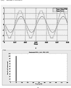
Fig. 4. Results of the improved projected 7-level symmetric method.
a) VL & I0 b) THD for I0
The MOSFET switching Plosses are planned for an equal power adjustment and then the results are comprehensive for the proposed CSI. The total switching Ploss is collected by two elements:
[image:3.595.312.565.132.444.2](i) IGBT (P losses) (ii) diode Plosses.
Fig. 5. Results of 15-level projected asymmetric method Io, VL and THD for Io.
A. Symmetrical Configurations
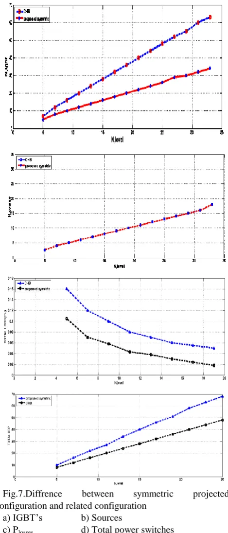
The considered asymmetrical configuration is contrasted and the configuration is proposed in [13] and the deviated CHB. The quantity of IGBTs V/s the quantity of current levels is appeared in Fig. 7a. This figure demonstrates that the projected inverter wants to bring down the quantity of IGBTs. Figs 7b– d demonstrates the quantity of sources, add up to controlling the misfortune and aggregate SDP, individually. Like symmetric approach, the quantity of sources in the projected method and CHB are equivalent [13]. The other angle which must looked at is the additive misfortunes. Thinking about Fig. 7c, because of a smaller number of active switches, the proposed asymmetrical method has brought down aggregate misfortunes divergence with uneven CHB and [13]. Be that as it may, the aggregate SDP of the uneven CHB configuration is lesser than the majority of the configurations, the quantity of IGBT’s diminished essentially in the projected construction. Different power converters, the quantity of IGBT’s decides
Fig. 6. Proposed asymmetrical fifteen-level structure
Fig.7.Diffrence between symmetric projected
Configuration and related configuration a) IGBT’s b) Sources
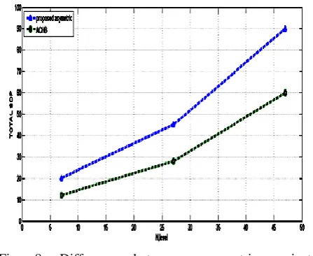
Fig. 8. Difference between asymmetric projected Configuration and related Configuration
a) IGBT’s b) Sources
c) Plosses d) Total power switches
IV. CONCLUSION
It projected new symmetric and asymmetric MCS formations are projected. The purposed CSI employs a pointed number of strategies associated with traditional structures. Further, it desires a smaller number of DC’s, “switches, and gate driver circuits”. A lesser number of compulsory devices prompt the lessening of aggregate usage price of rectifiers Likewise, the execution and governor will be basic. The projected inverter is contrasted and CHB’s and an as of late proposed converter and the examination comes about approve the highlights of proposed structures.
REFERENCES
1. Rodriguez, J., J.-S. Lai, and F.Z. Peng, Multilevel inverters: a survey of topologies, controls, and applications. IEEE Transactions on industrial electronics, 2002. 49(4): p. 724-738.
2. Veenstra, M. and A. Rufer, Control of a hybrid asymmetric multilevel inverter for competitive medium-voltage industrial drives. IEEE Transactions on industry applications, 2005. 41(2): p. 655-664. 3. Sivakumar, K., et al., A hybrid multilevel inverter topology for an
open-end winding induction-motor drive using two-level inverters in series with a capacitor-fed H-bridge cell. IEEE Transactions on Industrial Electronics, 2010. 57(11): p. 3707-3714.
4. Wiechmann, E.P., et al., On the efficiency of voltage source and current source inverters for high-power drives. IEEE Transactions on Industrial Electronics, 2008. 55(4): p. 1771-1782.
5. Ajami, A., et al., Developed cascaded multilevel inverter topology to minimise the number of circuit devices and voltage stresses of switches. IET Power Electronics, 2013. 7(2): p. 459-466.
6. Banaei, M.R., M.R.J. Oskuee, and F.M. Kazemi, Series H-bridge with stacked multicell inverter to quadruplicate voltage levels. IET Power Electronics, 2013. 6(5): p. 878-884.
7. Kadir, M.A., S. Mekhilef, and H. Ping, Voltage vector control of a hybrid three-stage 18-level inverter by vector decomposition. IET Power Electronics, 2010. 3(4): p. 601-611.
8. Turner, R., S. Walton, and R. Duke, Stability and bandwidth implications of digitally controlled grid-connected parallel inverters. IEEE Transactions on Industrial Electronics, 2010. 57(11): p. 3685-3694.
9. Li, H., Y. Luo, and Y. Chen, A fractional order proportional and derivative (FOPD) motion controller: tuning rule and experiments. IEEE Transactions on control systems technology, 2010. 18(2): p. 516-520.
AUTHORSPROFILE
Mrs. Himabindu, M. Tech (Ph.D.) presently working as Asst.Prof in Geethanjali college of Engineering and technology. She has 12 years of teaching experience. She obtained B. Tech in Electrical and Electronics Engineering with distinction and M. Tech in power electronics and industrial drives with distinction. She is pursuing Ph.D. from “Andhra University”, Vishakhapatnam. Area of Interest is electric drives and renewable energy sources.
[image:5.595.58.282.54.237.2]