SALMIDI BIN TARAJI
B050810274
UNIVERSITI TEKNIKAL MALAYSIA MELAKA
DIE DESIGN AND OPTIMIZATION TO REDUCE
UNIVERSITI TEKNIKAL MALAYSIA MELAKA
DIE DESIGN AND OPTIMIZATION TO REDUCE CAVITY IN
EXTRUSION PROCESS
This report submitted in accordance with requirement of the Universiti Teknikal Malaysia Melaka (UTeM) for the Bachelor Degree of Manufacturing Engineering
(Manufacturing Design)
by
SALMIDI BIN TARAJI B050810274
UNIVERSITI TEKNIKAL MALAYSIA MELAKA
BORANG PENGESAHAN STATUS LAPORAN PROJEK SARJANA MUDA
TAJUK: Die Design and Optimization To Reduce Cavity In Extrusion Process
SESI PENGAJIAN: 20010/11 Semester 2
Saya SALMIDI BIN TARAJI
mengaku membenarkan Laporan PSM ini disimpan di Perpustakaan Universiti Teknikal Malaysia Melaka (UTeM) dengan syarat-syarat kegunaan seperti berikut: 1. Laporan PSM adalah hak milik Universiti Teknikal Malaysia Melaka dan penulis. 2. Perpustakaan Universiti Teknikal Malaysia Melaka dibenarkan membuat salinan
untuk tujuan pengajian sahaja dengan izin penulis.
3. Perpustakaan dibenarkan membuat salinan laporan PSM ini sebagai bahan pertukaran antara institusi pengajian tinggi.
4. **Sila tandakan (√)
SULIT
TERHAD
TIDAK TERHAD
(Mengandungi maklumat yang berdarjah keselamatan atau kepentingan Malaysia yang termaktub di dalam AKTA RAHSIA RASMI 1972)
(Mengandungi maklumat TERHAD yang telah ditentukan oleh organisasi/badan di mana penyelidikan dijalankan)
Alamat Tetap:
No. 129 Sahabat 05 Blok 07, Desa Kencana, Peti Surat 61694 91125, Lahad Datu, Sabah.
Tarikh: _________________________
Disahkan oleh:
PENYELIA PSM
Tarikh: _______________________
DECLARATION
I hereby, declared this report entitled “Die Design and Optimization to Reduce Cavity in Extrusion Process” is the results of my own research except as cited in
references.
Signature : ……….
Author’s Name : SALMIDI BIN TARAJI
APPROVAL
This report is submitted to the Faculty of Manufacturing Engineering of UTeM as a partial fulfillment of the requirements for the Degree in Bachelor of Manufacturing Engineering (Manufacturing Design). The member of the supervisory committee is as follow:
……… Supervisor
ABSTRAK
ii
ABSTRACT
ACKNOWLEDGEMENT
First of all I am thankful to Almighty ALLAH, with His bless and mercy, I was successfully completed the PSM report as well. I would like to thank my family who has scarified so much of all that was they to give me good education. I cannot even begin to thank them for all they have done for me.
DEDICATION
This work is dedicated to My Father & Mother Taraji Bin Sanusi and Langka Binti Dammang their love and inspiration, my supervisor, my friend and who passed on a love of reading and respect for education.
TABLE OF CONTENTS
Abstrak i
Abstract ii
Acknowledgement iii
Dedication iv
Table of Contents v
List of Tables x
List of Figures xi
1.0 INTRODUCTION 1
1.1 Introduction 1
1.2 Problem Statement 1
1.3 Objective 2
1.4 Scope 2
1.5 Parts of The Extrusion Process 3
1.5.1 Die Assembly 4
2.0 LITERARTURE REVIEW 6
2.1 Introduction 6
2.2 Overview of Extrusion 6
2.3 History of Extrusion 8
2.4 Extrusion Process 10
2.4.1 Basic Principles Of Extrusion 10
2.4.2 Types of Extrusion 11
2.4.3.1 Direct Extrusion 11
2.4.3.2 Indirect Extrusion 12
2.4.3.3 Impact extrusion 12
2.4.3 Advantages of Extrusion 13
2.4.4 Limitations of Extrusion 13
2.5 Types of Equipment Used 14
vi
2.6 Standard Extrusion Shape 15
2.7 The Extrusion Product 15
2.8 Heat Treatment Process 16
2.8.1 Solution Heat Treatment and Age Hardening 16
2.8.2 Solution Heat Treating 17
2.8.3 Aging 19
2.9 Selection Material (Workpieces) 20
2.9.1 Guidelines For Alloy Selection 21
2.10 Die Design 22
2.10.1 Dimensions and Shapes of Extrusions 22
2.10.2 Dimensional Tolerances 22
2.10.3 Considerations in Die Design 23
2.10.4 Tolerances 23
2.10.5 Angular Dimensions 24
2.11 Theory Of Calculation For Extrusion Process 24
2.11.1 Extrusion Force 24
2.11.2 Extrusion ratio 25
2.11.3 Material Reduction 27
2.12 Theory of Plasticity 29
2.12.1 Applications of the Theory of Plasticity 30
2.12.2 Stress-Strain Behavior 30
2.13 Theory of elasticity 32
2.14 Finite Element Methods (FEM) 33
2.15 Finite element analysis (FEA) 34
2.15.1 Explicit Dynamic 35
2.15.2 DEFORM 3D 36
2.15.2.1 Analyzing Manufacturing Processes 37
3.0 METHODOLOGY 38
3.1 Introduction 38
3.2 Flow Chart 38
3.3 Project Details 39
3.3.1 Data mining 39
3.3.1.2 Die Design Information 41
3.4 Literature Review 42
3.5 Develop Design 42
3.5.1 Design Sketch 43
3.5.2 Comparison 43
3.5.3 CAD Design 44
3.5.4 Design Considerations 44
3.6 Finite Element Model 44
3.7 Boundary Condition 45
3.8 Simulation 45
3.8.1 Finite Element Analysis Stages 45
3.8.1.1 Pre-Processing 47
3.8.1.2 Simulation 47
3.8.1.3 Post-Processing 47
3.8.2 Analyze the Result 48
4.0 DETAIL DESIGN 48
4.1 Introduction 48
4.2 Design of Extrusion Die 48
4.3 Detail Design 51
4.4 Die Land Plate 52
4.5 Pre-land Plate 53
4.6 Transition Plate 54
4.7 Die Adapter Plate 56
4.8 Extruder Mounting Plate 57
4.9 Heater Band 58
4.10 Adding the standard component 59
5.0 ANALYSIS PROCEDURE 61
5.1 Introduction 61
5.2 Create The Database 61
5.2.1 Project Name and Title 62
5.2.2 Process Setting 63
viii
5.3.1 Primary Die (Pdie) 64
5.3.2 Object Type (OBJTYP) 65
5.3.2.1 Rigid 65
5.3.2.2 Elasto-Plastic (Ela-Pla) 65
5.3.3 Geometry Model 66
5.3.4 Model Meshing 66
5.4 Material properties 69
5.5 Model movement 70
5.5.1 Speed Control 70
5.6 Boundary conditions 71
5.6.1 Contact 71
5.6.2 Heat Exchange With The Environment 72
5.6.3 Temperature 73
5.6.4 Diffusion With The Environment 73
5.7 Contact Boundary Conditions 74
5.8 Stopping Controls 76
5.9 Step Controls 76
5.10 Database Generation 77
5.11 Simulate 78
5.12 Post-Processor 79
6.0 RESULT AND DISCUSSION 81
6.1 Introduction 81
6.2 Results of Worm Aluminium Extrusion Process 81
6.3 Total Structure Deformation 83
6.3.1 Strain 83
6.3.2 Stress 84
6.4 Thermal Stress 88
6.5 Comparison & Discussion 90
7.0 CONCLUSION AND RECOMMENDATION 92
7.1 Conclusion 92
x
LIST OF TABLES
2.1 A brief summary of extrusion history 8
2.2 Show the effect of aging on the properties of Aluminium Alloy 2014. 20
2.3 Alloy Selection 21
3.1 The material information of aluminium 41 3.2 The information of design extrusion Die 41
5.1 Data of object type for geometry model 65
5.2 The meshing data of all geometry 67
5.3 The material properties with application 69
5.4 Parameter data speed control 70
5.5 The contact relation Data of other component 75
5.6 The simulation control data 77
LIST OF FIGURES
1.1 The Extrusion Process 3
1.2 Schematic outline of forward extrusion process 4
2.1 Direct extrusion 11
2.2 Indirect extrusion 12
2.3 Impact extrusion 13
2.4 Standard extrusion shape 15
2.5 Scheme of direct extrusion 15
2.6 Extrusion principle 16
2.7 Age -hardening heat treatment phase diagram 17 2.8 Show the result the tensile strength of the material 18
2.9 Show the Changes in Microstructure 18
2.10 The hardness and tensile strength variation during aging and overaging 19
2.11 Direct Extrusion Process 25
2.12 Extrusion constant as a function of temperature for assorted metal.
Alter P. Lowenstein, ASTME paper 28
2.13 Microstructure of extruded UO2: (A) parallel to the extrusion direction
(B) Perpendicular to the extrusion direction. For Nuclear Metal.Inc 28 2.14 The Stress-Strain Curve with Effects of Unloading 31 2.15 Particles displacement simulation in the structure 32
2.16 Nominal and tangential constraints 33
3.1 Methodology of the Project 39
3.2 Flowchart of the develop design 43
3.3 The flow charts DEFORM 3D finite element analysis (FEA) stages. 46
4.1 External View of the Extrusion Die (Isometric View) 50 4.2 Explode View of the Extrusion Die (Isometric View) 50 4.3 Third angle projection view of the Extrusion Die (Four Views) 51
xii
4.5 Top view die land plate 52
4.6 Show the section view of die land plate and zooming curve on
details shape die 53
4.7 Top view die pre-land plate 53
4.8 The Dimension Curve Details in Shape Pre-land Die Plate, the
Section View of Die Land Plate and 3D-Solidmodel 54 4.9 Model of die transition plate (isometric view) 54 4.10 Top view and section detail dimension of die transit plate 55
4.11 Front view of die transit plate 55
4.12 The curve of die transit plate 55
4.13 3D model of die adapter plate 56
4.14 The details dimension curve of die adapter plate 56 4.15 First angle projection view of die adapter plate 57
4.16 3D model of extruder mounting plate 57
4.17 First angle projection view of extruder mounting plate 58
4.18 3D model of Heater Band 58
4.19 First angle projection view of Heater Band 59
4.20 Hex Flange Bolt Small ISO 59
4.21 Specific dimension of Hex Flange Bolt Small ISO 60
5.1 Opening DEFORM 3D Pre- Processor window 62
5.2 The Project Window. 63
5.3 Process setting window. 63
5.4 Pre-processor with the object tree in project view 64 5.5 For Geometry data options import with red box step 66
5.6 The model meshing window 67
5.7 The Remeshing Criteria Window 68
5.8 Result Meshing Workpiece (Aluminium) 68
5.9 The material library DEFORM 3D 69
5.15 Result the heat exchange defined 73 5.16 The parameter temperature and node contact condition 73 5.17 The result diffusion with environment on aluminium 74 5.18 The contact relation data of with other component 75
5.19 The simulation stopping control 76
5.20 The simulation control 77
5.21 The input checking and generate database 78
5.22 The simulate window 78
5.23 The simulate graphics 79
5.24 The post-processor window 79
5.25 Simulation Summary Window 88
6.1 The FEM model and extrusion parameters 82 6.2 The billet extended with different design die standard (a) and
optimization (b) 83
6.3 The result graph standard die design of the total strain-time 84 6.4 The result graph new die design of the total strain-time 84 6.5 The contours distribution of stresses for extrusion with different
standard die design (a) and new die design (b) 85 6.6 The result graph standard die design of the total stress-time 85 6.7 The result graph new die design of the total stress-time 86 6.8 (a),(b) Effective stresses and (c),(d) effective strain of the standard
die and new die design 87
6.9 The result graph standard die of the total stress-strain 87 6.10 The result graph new die design of the total stress-strain 88 6.11 The comparison result from standard die design and new die
design of the total temperature-time 88
6.12 The comparison result from standard die design and new die
design of the total heat flux 89
LIST OF ABBREVIATIONS
CAD - Computer Aided Design
FEM - Finite Element Modelling
FEA - Finite Element Analysis
ISO - International Organization for Standardization
CHAPTER 1
INTRODUCTION
1.1 Introduction
The die design, a large division of tool engineering, is a complex, fascinating subject. It is one of the most exciting of all the areas the general field of tool engineering. The word ‘die’ is very general one and it may be well to define its meaning as in this project report. It is used in two distinct ways. When employed in general sense, its mean an entire press tool with all component taken together. When used in a more limited manner, it refer to that components which is machined to receive the blank, as differentiated from the component called the ‘punch’ which is its opposite member.
In this project, the new die design of a proper punch and die will be discussed. Starting by designing model of extrusion die and optimize the main parameter are geometry model of punch and the angle of the die has been analyze using finite element analysis (FEA) software. Then few proposed optimization will be developed and be evaluated to find the best solution for the cavity problem.
1.2 Problem Statement
2
software allows the extrusion die to be turned three-dimensionally and for improvements to be made easily. Many specifications that must be considered before design the extrusion die.
Die design for a new product is developed on the basis of previous experience and experimentation. It is effective for analysis of material flow, temperature distribution and load estimation if die design is specified. But 3D simulation becomes time consuming when many simulation trials are required for development of die shape and searching for optimal position of orifice. By using the new software today, we not only can design the die extrusion but also can analysis the product in details. The defects from the design can be detected when doing a simulation on the product. By using FEA simulation software (Deform V10), the more precise and accurate result will be get.
1.3 Objective
The main objectives that have to be in consideration for this project; stated as below:
a) To design an extrusion die by using SolidWork software.
b) To simulate an extrusion die by using the DEFORM 3D FEA software c) To optimize the geometries parameters of extrusion die.
1.4 Scope
l.5 Parts of The Extrusion Process
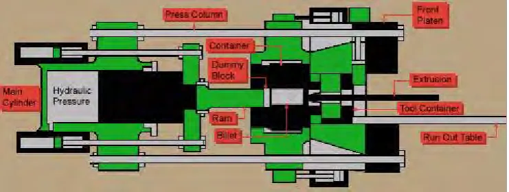
[image:23.595.135.506.221.361.2]Understanding how an extrusion press works requires identifying the press parts and explaining their use. An extrusion press is made up of a front platen and back platen held together by four tie rods. The parts of the press that actually make the extrusion are as follows:
Figure 1.1: The Extrusion Process (http://www.aec.org/techinfo/expro.html)
a) Main Cylinder- Chamber and cylinder of an extrusion press into which
hydraulic fluid is pumped to generate the desired ram pressure and movement.
b) Hydraulic Pressure- Pressure used to move the ram forward at the required
Pounds Per Square Inch.
c) Ram- A steel rod attached to the main cylinder with a dummy block on the
end that enters the container and applies pressure to the billet.
d) Dummy Block- A tight fitting steel block attached to the ram stem on a press
which seals the billet in the container and prevents metal from leaking backward.
e) Billet- Aluminium log cut to specific lengths which are fed into the press as
extrusion materials.
f) Container- Chamber in an extrusion press which holds the billet as it is
4
g) Tool Stack (Die Assembly)- solid: die ring, die, backer, bolster, and
sub-bolster (Sub-sub-bolsters are not used in Carthage or Newnan). Hollow: die ring, die mandrel, die cap, bolster, sub-bolster
l.5.1 Die Assembly
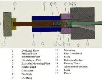
[image:24.595.152.481.320.582.2]Extrusion apparatus for extruding aluminium materials wherein the material is introduced into an extrusion chamber and through a plurality of extrusion orifices located in an extrusion plate closing off one end of the extrusion chamber. The extrusion orifices are circumferentially spaced about the center of the die plate.
Figure 1.2: Schematic outline of forward extrusion process (http://www.extrudedprofilesworld.com/extrusion-press.html)
a) Die Holder- Container of the tool stack.
b) Die Lock- Locks the die into the die holder.
c) Log Oven/ Billet Oven- Press component used to heat the logs/ billets to