This is a repository copy of
On the calculation of energy release rate in composites by
Finite Elements, Boundary Elements and Analytical Methods
.
White Rose Research Online URL for this paper:
http://eprints.whiterose.ac.uk/90589/
Version: Accepted Version
Article:
Tafazzolimoghaddam, B. and Curiel-Sosa, J.L. (2015) On the calculation of energy release
rate in composites by Finite Elements, Boundary Elements and Analytical Methods.
Composites: Mechanics, Computations, Applications, An International Journal, 6 (3). 219 -
237. ISSN 2152-2057
https://doi.org/10.1615/CompMechComputApplIntJ.v6.i3.40
[email protected] https://eprints.whiterose.ac.uk/ Reuse
Unless indicated otherwise, fulltext items are protected by copyright with all rights reserved. The copyright exception in section 29 of the Copyright, Designs and Patents Act 1988 allows the making of a single copy solely for the purpose of non-commercial research or private study within the limits of fair dealing. The publisher or other rights-holder may allow further reproduction and re-use of this version - refer to the White Rose Research Online record for this item. Where records identify the publisher as the copyright holder, users can verify any specific terms of use on the publisher’s website.
Takedown
If you consider content in White Rose Research Online to be in breach of UK law, please notify us by
__________________________________________________________ * Corresponding author. Tel.: +44 - (0)114-22-26077
Email: [email protected]
On the calculation of energy release rates in composite laminates by
Finite Elements, Boundary Elements and Analytical Methods
B. Tafazzolimoghaddam, J.L. Curiel-Sosa
Department of Mechanical Engineering, University of Sheffield, Sir Fredric Mappin Bld., Mappin St., Sheffield, S1 3JD, UK
________________________________________________________________________________________________________________
Key Words: J-Integral, Energy Release Rate, Finite Element Analysis, Boundary Element Method, Transversal Crack, Virtual Crack Closure Technique
A B S T R A C T
_________________________________________________________________
To characterise a transversal crack evolution in a cross-ply [0/90]s fibre reinforced composite laminate, the associated energy release rate (ERR) was calculated by means of the J-integral embedded into the Finite Element Method (FEM). The ERR values computed for the propagation of the transversal crack were correlated to the ones obtained by using the Virtual Crack Closure Technique (VCCT) embedded within the Boundary Element Method (BEM). In addition, the results were compared with analytical values. The results correlated well except when the crack length was approximately 80% of the ply thickness. In such case, ERR values showed some discrepancies between FEM and BEM. The reason stems from the fact that in the VCCT used not all components of the stresses are considered, resulting in smaller ERR values. In addition, the results proved that transversal cracks can influence each other only in a limited distance.
1. Introduction
Matrix cracks often appear prior to other damage modes in composite materials. It is well known that the fracture process starts at micro-level as soon as the laminate is subjected to loading. In cross ply fibre reinforced laminates subjected to unidirectional loading micro-cracks appear immediately in the 90 plies. Increasing the load can lead to their coalescence and formation of macro-transverse cracks [1],[2]. Propagation of transverse cracks toward the interface can lead to other failure modes such as delamination or fibre fracture [3]. To assess the integrity of the laminate, transversal cracks can be modelled; although this has proved challenging due to shortcomings such as gradual redistribution of stress during fracture and degradation of mechanical properties [4], [5].
Characterizing the conditions which lead to failure of a composite laminate due to transversal cracks triggering delamination between laminae is a long-standing research topic [6], [7], [8], [9]. Studies on related engineering applications such as helicopter rotor blades prone to matrix cracking preceding fibre breaking [10], [11], cracking of large laminates used in wind turbines [12], damage created by hail ice impacts on leading-edge, control surfaces, engine nacelles, fan blades of aircrafts [13], and soft body impact [14] can be found in the literature. εodelling
progressive damage [15] and [16], and prediction of fracture in composite laminates with different techniques, such as extended Finite Element εethod (XFEε) [17], is another area of interest for obvious critical-safety reasons.
Researchers have attempted to predict different modes of failure in composite materials by using the energy release rate (ERR) as a fracture criterion. The modes of failure include but not limited to: compressive and inter-laminar
shear failure in aerospace laminates [18], delamination growth due to buckling [5] and inter-ply cracking in
adhesive-bonded aircraft composite joints [19].
ERR calculation for delamination and the singular stress at the crack tip is represented in terms of the stress resultant jumps across the delamination front. This approach can eliminate the oscillations in stress when incorporated in a finite element framework [5]. Conversely, VCCT with solid finite elements results in oscillatory stresses and displacements in front of the crack tip, which may cause divergence [22]. The use of VCCT within a boundary element framework (BEε) is deemed more appropriate because the boundaries of the problem are directly related to the problem features such as fracture parameters (see París et al.[1]). París and co-workers [1] considered different
conditions (e.g. models with and without delamination) and calculated the ERR for different crack lengths. Their results were in good agreement with the analytical results by εcCartney [23].
The J-integral approach as a measure of the energy release rate associated with crack propagation whereby a criterion
can be introduced in terms of a bounding limit value has been studied in [24], [25] among others. One of the advantages of using J-integral is that under quasi-static conditions, it is equal to the energy release rate G for linear
elastic materials. For two dimensional problems in a mixed fracture mode (mode I and mode II) loading the relation between stress intensity factor and J-Integral is
(1)
where J denotes J-integral and, KI and KII are the stress intensity factors corresponding to mode I and mode II
fracture, respectively. E and v denote elastic modulus and Poisson’s ratio respectively. The domain integral method is often integrated in commercial packages, e.g. Abaqus, to take advantage of J-integral path independency.
In this paper, parametric studies by finite element analysis with different specimen and crack lengths are conducted and compared with results by VCCT-BEε and analytical means. Results showing the stress distribution in the
composite laminate are provided for better assessment of the structural integrity of the composite. In addition, discussion about finite element modelling features for ERR calculation is presented.
2. Background: J-integral
2.1 Finite element J-Integral calculation
J. R. Rice in 1968 [25] formulated Eshelby’s [26] contour integral for crack problems. For an edge crack in a nonlinear elastic body the J-integral equals the rate of change (with respect to crack growth, da) in potential energy
Up:
(2)
By definition, J-integral is equal to ERR if the material behaviour is linear and elastic. This definition is between
Griffith’s model of fully elastic and that of Irwin’s with a small crack tip plasticity [27]. Fig.1. shows the contour surrounding crack tip singularity in a semi-infinite two dimensional body.
Fig.1. Integration path around crack tip
X1
X2
The change in potential energy for infinitesimal crack extension is:
lim (3)
Where is the crack growth and A is the area encompassed by the contour, W is the elastic strain energy, ui is the
displacement, is the traction and ds is an infinitesimally small section of contour .
Applying the Green’s theorem, it is possible to write Eq. (3) in the form of a line integral:
with
(4)
(5)
nj is the normal vector to the integration path and is the stress component on . The density of energy is expressed
as:
(6)
For linear elastic material elastic strain energy is related to stress and strain as:
(7)
The material within the contour integral is assumed homogeneous and the process is time independent. δine integrals have difficulty of implementation in FE and domain integrals are preferred [28]; unlike VCCT which uses nodal values for ERR calculation. δi et al [29] showed that line integral can be transformed into an equivalent area integral as shown in Fig.2.
Fig.2. Domain definition for area integral
lim n (8)
The process is assumed isothermal and body forces are neglected. n is the unit vector normal to and 1i is the
Kronecker delta. This formula can be rewritten in the form
(9)
C is the closed curve C=C1+C++C-- and q1 is a smooth function in C domain which is unity on and 0 on C1, m1=0
and m2=±1 on the crack surfaces and mj=-nj on . The second integral vanishes because of traction free surfaces of
the crack. By applying the divergence theorem to the close contour (9):
(10)
A is the area enclosed by C. To implement this integration within the FEε, Shih et al [28] formulated the discretized form of Eq.(10) by means of Gaussian integration:
(11)
Where
(12)
For a quadrilateral element. ζI are the shape function and Q1I is the nodal value for Ith node. Q1I is zero on C1 and 1
on . Using the chain rule we have:
(13)
where is the inverse Jacobean matrix of transformations:
, i=1,2 (14)
Nk are the shape functions.
3. Modelling of Transverse Crack in [0/90]s laminate
A schematic view of the tested laminate composite HexPly8552 is shown in Fig.3. The thickness of each lamina is
When the [0/90]s laminae is under uniaxial loading, transversal cracks appear on the 90º ply and, then, progress
towards the interface with the 0º ply. Further details of this can be found in the works by Dvorak and δaws [31] and Wang [32]. As the crack is assumed to be through the width [1]. A two dimensional model is justified for analysis.
[image:6.595.205.413.140.254.2]
Fig. 3. Transverse crack in [0/90]s laminate
The properties for the laminate used are extracted from Hexcel datasheets [33]. This toughened epoxy resin system is made of unidirectional glass fibres. It is used in aerospace structures present in commercial airplanes, helicopters and jet engine parts.
Table1. Material properties for Hexeply8552. All the values for E and G are in GPa. E11 represents fibre direction elastic module.
E11 E22 E33 G12 G23 G13 12 13 23
141.3 9.85 9.58 5 3.5 5 0.3 0.3 0.32
The fibre tensile strength is 2207 εPa. The transversal –resin- strength is 81 εPa. The laminate thickness is much
smaller than the other two dimensions, i.e. width and length. Therefore, the strain in perpendicular direction can be neglected and, hence, a plane strain state can be assumed.
εcCartney proposed the ERR analytical solution for the [0/90]s laminae. His calculation is based on the Gibbs free
energy [1]:
(15)
By substituting = E, renders that,
(16)
The ERR is calculated as the infinitesimal variation of G respect to the crack propagation (∂a):
(17)
In εcCartney’s solution, , E and are axial components of stress, Young’s modulus and strain in the first principal direction respectively. In this case, the principal direction is denoted as y-direction. París et al [1] calculate ERR by
means of VCCT-BEε. VCCT calculates the ERR by multiplying the displacement of crack face nodes by the force
required for crack closure at each node [1]. The interested reader is referred to reference [34] for further details.
4. 2D Cross-ply Laminate Model
The cross section of the laminate is modelled as two sections with separate material definition. ζo adhesive layer exists at the interface. The model represents half of the specimen in both vertical and horizontal directions where
y z x
symmetric boundary conditions can apply. In this case only one surface of the crack is drawn, Fig.4. The analysis is quasi static and Abaqus standard solver is used.
Fig.4. Boundary conditions and crack illustration.
In order to evaluate the results, the work by Blázquez et al [1] using VCCT-BEε and the work by εcCartney [23]
using analytical methods are used for comparison. Four contours were used in the test to check the consistency of the results. As the model dimension relatively large in to z direction, plain strain element is used. Furthermore, it is necessary to define the mesh such that the contour does not overlap the adjacent ply and to remain neatly homogeneous. The crack length was varied between 0 and 0.55 mm (which is 90 plies thickness) at 0.1mm intervals (smaller intervals were used near the interface as the mesh had to be refined). Four different model lengths, δ, were tried (0.5mm, 1mm, 2mm, and 4 mm).
5. Results and Discussion
5.1 ERR for Different Crack δengths
Fig.(5) shows the ERR calculated for δ=2mm from three different methods (FEε, theoretical and Bδε). J-integral
values are slightly higher than those of BEε and analytical solutions. FE solver considers transverse stresses which are not considered in VCCT. Therefore g higher value of ERR is achieved. The maximum value is observed approximately at a=0.4 mm. Theoretically, the crack progresses if ERR is beyond the critical value Gc.
Fig.5. ERR for L=2 mm. The crack will extend unstably after a = 0.1 mm
0o ply =0.01, =0
=0 =0
Crack a
L
u= 0
0.55mm 0.55mm
uy= 0
0 0.2 0.4 0.6 0.8 1
0 0.1 0.2 0.3 0.4 0.5
ER
R
(
K
J/
m
2)
FEM Analytical BEM
For Hexply8552 Gc is equal to 0.3 KJ/m2 for mode one crack opening [33]. For this load setting Gc is attained
approximately a=0.1mm. When this value is reached the crack extends until somewhere between the maximum ERR and the interface where ERR becomes zero [1]. Theoretically because the ERR decreases to very small amount near the interface the crack must stop just before reaching the 0 ply. In the stress analysis it is clearly visible that for cracks so close to the interface the normal tension at the interface is much larger than the material strength and delamination might happen prior to the crack reaching the interface.
5.2 Transverse Crack Separation Length
Fig.(6) shows the variation of J-integral at similar strain for different model lengths (δ=0.5mm, 1mm, 2mm and 4
mm). At δ=2 mm, which is twice as large as the model thickness, the neighbouring cracks do not have influence on each other and larger specimens have the same ERR curve (Fig.6). This means that the crack existence does not affect the stress distribution on distances twice as large as the models’ thickness.
Fig.6. Comparison of ERR for different specimen length. If L greater than 2mm, the ERR for different lengths have small difference
There is a specific pattern for transverse cracks in composite materials which is related to the geometry and material that also constrains the number of cracks that can develop in the matrix. This limit is known as upper limit or
“saturation state” [3] which can be related to the separation length. The stress releases because of the crack occurrence can only influence within certain distance.
5.3 Effect of mesh size and contour path
ABAQUS uses the contour integral method to calculate J-integrals. It automatically selects a node at the crack tip for
the inner contour and the outer contours that pass through adjacent nodes. The contour should be confined within the homogeneous area. Fig.(7) depicts distinct contour . εesh size analysis showed that for mesh sizes as large as 0.2 mm to very small mesh sizes (mesh size 0.01mm) convergence is attainable. It also showed independence of J
-integrals to mesh size.
Fig.7. Contours around crack tip singularity in ABAQUS.
0 0.2 0.4 0.6 0.8 1
0 0.1 0.2 0.3 0.4 0.5
ER
R
(
K
J/
m
2)
a (mm) L=2 mm
The first contour shows slightly higher value compared to the larger contours. ζo matter what the mesh size is Fig.(9). ABAQUS help suggests mesh refinement for accurate results and neglecting the first two contour outcomes. The approximation of FEA slightly affects the results of J-integrals but it must be noted that mesh refinement should
not be related to contour integral accuracy. For the first contour, the error stem from crack tip singularity definition. This means mesh refinement does not increase the J-Integral accuracy anyway. This was also argued by Brocks and
Scheider [35].
ABAQUS can use quarter-node element to create r-1/2 singularity at crack tip by shifting the mid node of quadrilateral
element toward the singularity (Fig.9). Barsoum [36] proposed this method for elastic and plastic crack tip region but Carka and δandis [37] suggested it is more suitable for linear elastic material.
Fig.8. Quarter-point element technique shifts mid-node in 8 node quadrilateral element toward the crack tip to model singularity
The stress distribution close to the singularity is strongly dependant on the distance between the singularity and the mid-element node. In order to clarify the effect of quarter-point element on the J-integrals a test was run by changing
the position of mid-element node along element side. The results show that the optimum position for the shifted node
is around 25% of the element side length (Fig.9).
This might also show that this distance gives more accurate stress distribution for singularity, as it produced closer results for the J-integral.
Fig.9. First contour integral result is ruled by the position of mid-node. lqp is the mid-node distance to singularity and le is the length of the element. 5.4 Stress Distribution
When the crack progresses toward the interface, the normal stress and shear stress are changed significantly and can trigger other forms of failure including delamination. Figs.10a and 10b show the change in normal stress at the interface as the crack tip gets closer. The crack tip exerts large tensile force on the interface ahead of the crack.
0.74 0.75 0.76 0.77 0.78 0.79 0.8 0.81 0.82 0.83
0.2 0.25 0.3 0.35 0.4 0.45 0.5 0.55 0.6 0.65 0.7 0.75 0.8
ER
R
(
K
J/
m
2)
lqp/l
first contour
second contour third contour
(a) (b)
Fig.10. (a) Normal stress distribution along the interface for L=2mm and crack very close to the interface (b) Zoom in normal stress close to the crack tip area along interface for L=2mm and the crack near the interface
(a)
(b)
(c)
(d)
(e)
(f)
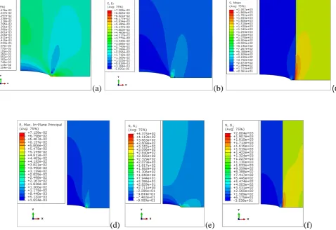
Figure 11 (a) Strain in transverse direction (zoomed) (b) Strain in loading direction (zoomed) (c) von Mises stress (zoomed) (d) Maximum in-plane principal strain (e) Stress in normal direction to loading and (f) Stress in loading direction for L=2 mm and a=0.5mm
The normal stress has a sudden increase when the crack is about to reach the interface and pushes normal stress to above the yield strength of the resin (approximately 81εPa). Concurrently, the normal stress decreases moving away from y=0 axis and between 0.1mm and 1mm, it is mostly compressive force at the interface. For cracks this close to the interface the specimen is experiencing large stresses but the J-integral does not predict crack propagation.
Fig.(11) provides stress and strain contours as well as von εises stress for a=0.5mm.
-50 0 50 100 150 200 250 300 350
0 0.5 1
a=0.45 mm a=0.5mm a=0.52mm a=0.54mm S tr ess x (M p a)
stress at the interface y (mm)
-50 0 50 100 150 200 250 300 350 400
0 0.1 0.2 0.3
a=0.45 mm a=0.5 mm a=0.52 mm a=0.54 mm S re ss x ( M P a)
[image:10.595.45.559.91.243.2] [image:10.595.67.546.313.641.2] [image:10.595.89.506.483.642.2]For shear stress (Fig.12) there is an alteration of direction at distances close to y=0. For a=0.54 mm (Fig.12), the shear stress is not zero at y=0 -unlike other crack lengths- because of the singularity definition.
As the tensile stress is far greater than the strength of resin at the interface, it is not realistic to consider a transverse crack without addressing delamination. París et al. investigated ERR for transverse crack when there is a delamination and the results showed that the ERR is the same for most of the crack lengths for cases when the crack tip is further than 0.1mm from the interface [1]. Also in an experimental study, París et al. verified their results on the transverse crack arresting just before reaching the interface and the effect of such cracks on delamination [42].
Fig.12. Shear stress at interface
6. Conclusion
ERR is a key factor in fracture analysis and, therefore, there is a genuine interest by engineers in developing accurate tools for its evaluation. The present study has compared three different methodologies for the calculation of the ERR associated to transversal crack in a [0/90]s laminate. Those are:
- The J-integral embedded into FEε.
- The VCCT embedded within BEε and,
- Analytical means.
The following remarks can be highlighted:
ERR values were well-correlated by all three methodologies except when the crack length was
approximately 80% of the ply thickness, i.e. to a 20% distance of the interface between distinct plies. VCCT neglects the transversal stress in this implementation of BEε and also the analytical expression that is the possible reason for smaller value of ERR. Therefore, it results in a certain difference only at the aforementioned distance in which that neglected component is significant.
ζo mesh dependence was observed with the FEε for the calculation of the J-integral, although the number
of contours used can effect at some point.
The effect of displacing the mid-element node was investigated in this work. It was showed that the
inaccuracy of the J-integral first contour is due to the definition of the singularity. The first contour provided
the closest result when the mid node is placed at ¼ element length from the singular point.
-30 -10 10 30 50 70
0 0.5 1 1.5 2
a=0.45 mm a=0.5 mm a=0.52 mm a=0.54 mm
S
h
ea
r
S
tr
ess
(
M
P
a
)
The stress distribution at the interface was also presented. It was observed that the stress reaches the maximum allowable at the interface between distinct plies when the transverse crack is very close to the interface.
Acknowledgment
The author would like to thank Dr. A. Blázquez for providing data for this analysis.
References
[1] F. París, A. Blázquez, L. N. McCartney and V. Manticˇ, “Characterization and evolution of matrix and interface related damage in [0/90]S
laminates under tension. part I: Numerical predictions,” Composites science and technology, pp. 201. 70 (7), 1168-1175, 2010.
[2] J. Berthelot, “Transverse cracking and delamination in cross-ply glass-fibre and carbon-fibre reinforced plastic laminates: static and fatigue
loading,” Appl Mech Rev, pp. 56:111-47, 2003.
[3] K. L. Reifsnider, “Fatigue of Composite Materials,” vol. 4, 1991.
[4] E. J. Barbero and D. H. Cortes, “A mechanistic model for transverse damage initiation, evolution, and stiffness,” vol. 124–132, 2010.
[5] Z. Zou, S. R. Reid, S. Li and P. D. Soden, “General expressions for energy-release rates for delamination in composite laminates,”
Proceedings of the Royal Society A: Mathematical, Physical and Engineering Sciences, pp. 458(2019): p. 645-667, 2002.
[6] S. Lim and S. Li, “Energy release rate for transverse cracking and delaminations induced by transverse cracks in laminated composites,
Comput Part A:,” Appl Sci Manuf, p. 36(11):1467–76, 2005.
[7] J. Wang and B. Karihaloo , “Matrix crack-induced delamination in composite laminates under transverse loading,” Compos Struct, p. 38:661–
6., 1997.
[8] Z. Petrossian and M. Wisnom, “Prediction of delamination initiation and growth from discontinuous plies using interface elements,”
Composites A, p. 29:503–15., 1998.
[9] J. Zhang, J. Fan and K. P. Herrmann, “Delaminations induced by constrained transverse cracking in symmetric composite laminates,” Int. J
Solids Struct, p. 36:813–46., 1999.
[10] P. M. Pawar and R. Ganguli, “Modeling multi-layer matrix cracking in thin walled composite rotor blades,” Journal of the American Helicopter
Society, pp. 50(4): p. 354-366., 2005.
[11] N. Roy and R. Ganguli, “Helicopter rotor blade frequency evolution with damage growth and signal processing,” Journal of Sound and
Vibration, pp. 283(3-5): p. 821-851, 2005.
[12] L. Overgaard, E. Lund and P. P. Camanho, “A methodology for the structural analysis of composite wind turbine blades under geometric and
material induced instabilities,” Computers and Structures, pp. 88(19-20): p. 1092-1109., 2010.
[13] H. Kim and K. T. Kedward, “Modeling hail ice impacts and predicting impact damage initiation in composite structures,” AIAA Journal, pp. 38(7): p. 1278-1281, 2000.
[14] A. F. Johnson and M. Holzapfel, “Modelling soft body impact on composite structures,” Composite Structures, pp. 61(1-2): p. 103-113, 2003.
[15] J. L. Curiel Sosa , S. Phaneendra and J. J. Munoz, “Modelling of mixed damage on fibre reinforced composite laminates subjected to low
velocity impact,” Int J Damage Mechanics, Vols. 22(3), 356-374, 2013.
[16] J. L. Curiel-Sosa, “Finite element analysis of Progressive Degradation versus failure stress criteria on Composite damage mechanics. In: Brahim Attaf (ed.). Advances in composite materials - ecodesign and analysis,” InTech, p. 429, 2011.
[17] J. L. Curiel Sosa and N. Karapurath, “Delamination modelling of GLARE using the extended finite element method,” Composites science and technology, pp. 72 (7), 788-791, 2012.
[18] M. L. Costa , S. F. S.F.M. De Almeida and M. C. Rezende, “Critical void content for polymer composite laminates,” AIAA Journal, pp. 43(6): p.
1336-1341., 2005.
[19] A. Chadegani, S. S. Smeltzer and C. Yang, “Adhesive-bonded composite joint analysis with delaminated surface ply using strain-energy
release rate,” Journal of Aircraft, pp. 49(2): p. 503-520, 2012.
[20] Banks-Sills and Leslie, “Application of the finite element method to linear elastic fracture mechanics,” Applied mechanics reviews, pp. 44 (10), 447-461, 1991.
[21] D. Xie, A. M. Waas, W. K. Shahwan, A. J. Schroeder and G. R. Boeman, “Computation of Energy Release Rates for Kinking Cracks based
on Virtual Crack Closure Technique,” Vols. CMES, vol.6, no.6, pp.515-524, 2004.
[22] I. S. Raju, M. A. Aminpour and J. H. Crews Jr, “Convergence of strain energy release rate components for Edge-Delaminated composite laminates,” Engineering Fracture Mechanics, pp. 30 (3), pp. 383-396, 1988.
[23] L. N. McCartney, “ Predicting transverse crack formation in cross-ply laminates,” Composites science and technology, pp. 58 (7), 1069-1081.,
1998.
[24] L. J. Lee and D. W. Tu, “J-integral for delaminated composite laminates,” Composites Science and Technology, pp. Volume 47, Issue 2,
1993, Pages 185-192, ISSN 0266-3538.
35, pp. 379-386, 1968.
[26] J. D. Eshelby, “The Determination of the Elastic Field of an Ellipsoidal Inclusion and Related Problems,” Solid State Physics, vol. Series:A.
Vol. 241, p. Vol.3, 1957.
[27] J. Lemaitre and J. L. Chaboche, Mechanics of solid materials, Cambridge U.P., 1994.
[28] C. F. Shih, B. Moran and T. Nakamura, “Energy release rate along a three-dimensional crack front in a thermally stressed body,” International
Journal of Fracture, pp. 30 (2), pp. 79-102, 1986.
[29] F. Z. Li, C. F. Shih and A. Needleman, “A comparison of methods for calculating energy release rates,” Engineering Fracture Mechanics, pp.
21 (1985) 405-421.
[30] C. Atkinson and J. D. Eshelby, “The flow of energy into the tip of a moving crack,” International Journal of Fracture, pp. 4, pp. 3–8., 1968.
[31] L. N. Dvorak GJ, “Analysis of progressive matrix cracking in composite laminates. II. First ply failure,” J Comput Mater , p. 21:309–29, 1987.
[32] A. Wang, “Fracture mechanics of sublaminate cracks in composite materials,” ComputTechnol Rev, p. 6(2):45–62, 1984.
[33] Hexcel Composites, “HexPly 8552,” Feburary 2013. [Online]. Available:
http://www.hexcel.com/Resources/DataSheets/Prepreg-Data-Sheets/8552_eu.pdf. [Accessed 2013].
[34] R. Krueger, “Virtual crack closure technique: History, approach, and applications,” Applied mechanics reviews, pp. 57 (1-6), 109-143, 2004.
[35] W. Brocks and I. Scheider, “Reliable J-Values - Numerical Aspects of the Path-Dependence of the J-Integral in Incremental Plasticity,”
Materialprüfung, pp. Vol. 45, 6, 264 - 275, 2003.
[36] R. Barsoum, “Triangular Quarter-Point Elements as Elastic and Perfectly-Plastic Crack Tip Elements,” International Journal for Numerical
Methods in Engineering, pp. , vol. 11, 1977, pp. 85-98.
[37] D. Carka and C. Landis, “On the Path-Dependence of the J-Integral Near a Stationary Crack in an Elastic-Plastic Material,” J. Appl. Mech.,
pp. 78(1):011006-011006-6. doi:10.1115/1.4001748, 2010.
[38] ABAQUS, “ABAQUS Tutorial/documentation. Help within ABAQUS program for users,” 2011. [Online]. [Accessed 10 2012].
[39] L. SH and S. Li, “Energy release rate for transverse cracking and delamination induced by tharsverse crack in laminated composites,” Applied
Science and Manufacturing, p. Computational Part A, 2005.
[40] D. Broek, “The practical use of fracture mechanics,” Kluwer. Springer., 1989.
[41] R. Krueger, “The Virtual Crack Closure Technique: History, Approach and Applications,” Vols. ICASE Report No. 2002-10, no.
NASA/CR-2002-211628, 2002.
[42] París, F., Blázquez, A., McCartney, L.N., Barroso, A. "Characterization and evolution of matrix and interface related damage in [0/90]S
![Fig. 3. Transverse crack in [0/90]s laminate](https://thumb-us.123doks.com/thumbv2/123dok_us/7916551.190939/6.595.205.413.140.254/fig-transverse-crack-in-s-laminate.webp)