UNIVERSITI TEKNIKAL MALAYSIA MELAKA
AUTOMATIC PET FEEDER USING RASPBERRY PI
This report is submitted in accordance with requirement of the Universiti Teknikal Malaysia Melaka (UTeM) for the Bachelor of Computer Engineering Technology
(Computer Systems) with Honours
by
NURNABILAH BINTI ZAKARIA B071310772
941108-03-5710
UNIVERSITI TEKNIKAL MALAYSIA MELAKA
BORANG PENGESAHAN STATUS LAPORAN PROJEK SARJANA MUDA
TAJUK: Automatic Pet Feeder using Raspberry Pi
SESI PENGAJIAN: 2016/17 Semester 1
Saya NURNABILAH BT ZAKARIA
mengaku membenarkan Laporan PSM ini disimpan di Perpustakaan Universiti Teknikal Malaysia Melaka (UTeM) dengan syarat-syarat kegunaan seperti berikut:
1. Laporan PSM adalah hak milik Universiti Teknikal Malaysia Melaka dan penulis. 2. Perpustakaan Universiti Teknikal Malaysia Melaka dibenarkan membuat salinan
untuk tujuan pengajian sahaja dengan izin penulis.
3. Perpustakaan dibenarkan membuat salinan laporan PSM ini sebagai bahan pertukaran antara institusi pengajian tinggi.
4. **Sila tandakan ( )
SULIT
TERHAD
TIDAK TERHAD
(Mengandungi maklumat yang berdarjah keselamatan atau kepentingan Malaysia sebagaimana yang termaktub dalam AKTA RAHSIA RASMI 1972)
(Mengandungi maklumat TERHAD yang telah ditentukan oleh organisasi/badan di mana penyelidikan dijalankan)
(TANDATANGAN PENULIS)
Alamat Tetap:
Lot 1452
Kampung Kekabu Lemal,
17000 Pasir Mas, Kelantan, Malaysia.
Disahkan oleh:
(TANDATANGAN PENYELIA)
Cop Rasmi:
iii
DECLARATION
I hereby, declared this report entitled “Automatic Pet Feeder using Raspberry Pi” is the results of my own research except as cited in references.
Signature :
Name : NURNABILAH BINTI ZAKARIA
iv
APPROVAL
This report is submitted to the Faculty of Engineering Technology of UTeM as a partial fulfillment of the requirements for the degree Bachelor of Computer Engineering Technology (Computer Systems) with Honours. The member of the supervisory is as follow:
v
ABSTRACT
vi
ABSTRAK
vii
DEDICATIONS
Alhamdulillah, praise to the Almighty Allah S.W.T
This project is dedicated to:
My mom Rohana Ismail, My beloved family,
My Supervisor Sir Zulhasnizam Hasan,
viii
ACKNOWLEDGMENTS
First and foremost, I would like to take a deepest appreciation to my supervisor Mr. Zulhasnizam bin Hasan from the Faculty of Engineering Technology University Technical Malaysia Melaka for his essential supervision, patience, motivation, enthusiasm, and immense knowledge towards the completion of this project.
I would also like to express my deepest gratitude to my classmates for their continuous support throughout the achievement of this project.
ix
TABLE OF CONTENTS
DECLARATION... iii
APPROVAL ... iv
ABSTRACT……….v
ACKNOWLEDGMENTS ... 8
TABLE OF CONTENTS ... 9
LIST OF TABLE ... xiv
LIST OF SYMBOLS AND ABBREVIATIONS ... xv
CHAPTER 1 ... 1
1.1 Introduction ... 1
1.2 Background ... 1
1.3 Problem Statement ... 2
1.4 Objectives ... 2
1.5 Scope of projects ... 3
1.6 Significant of study ... 3
1.7 Structure of project ... 4
CHAPTER 2 ... 5
2.1 Introduction ... 5
2.2 Raspberry Pi ... 5
2.2.1 History of Raspberry Pi ... 6
2.2.2 Raspberry Pi 2, Model B ... 6
2.2.3 Comparison between different Raspberry Pi models ... 7
2.2.4 Power supply for Raspberry Pi ... 9
2.3 Infrared sensor ... 11
2.3.1 Working principle of IR sensor ... 12
2.3.2 Infrared Sensor Circuit or Obstacle Sensing Circuit ... 13
2.4 Ultrasonic Sensor ... 14
2.5 Servo Motor ... 15
2.6 Android Application ... 16
x
2.7 Past Related Search ... 17
2.7.1 Intelligent Pet Monitor System with the Internet of Things... 17
2.7.2 Online DIY Timed Pet Feeder from Instructables ... 18
2.8 Pet Feeding System ... 19
2.8.1 Self-Replenishing Feeders ... 19
2.8.2 Automatic Timed Feeders ... 20
2.9 Conclusion ... 21
CHAPTER 3 ... 22
3.1 Introduction ... 22
3.2 Project Methodology ... 22
3.3 Block Diagram ... 24
3.3.1 Raspberry Pi ... 24
3.3.2 Infrared Sensor ... 25
3.3.3 Ultrasonic Sensor ... 26
3.3.4 Servo Motor ... 26
3.3.5 Pet Feeder Valve ... 26
3.3.6 Android Application ... 26
3.4 NOOBS (New Out Of Box Software): Raspbian Operating System ... 27
3.5 Raspberry Pi Programming: Python ... 28
3.5.1 Python: time library ... 29
3.5.2 Python: RPi.GPIO library ... 29
CHAPTER 4 ... 30
4.1 Introduction ... 30
4.2 Project Software ... 30
4.2.1 Python Files ... 30
4.2.2 Connecting Pushover application with Raspberry Pi ... 33
4.3 Project Hardware and Electronic Component ... 34
4.3.1 Connecting ultrasonic sensor with Raspberry Pi ... 34
4.3.2 Connecting Infrared sensor with Raspberry Pi ... 36
4.3.3 Connecting servo motor with Raspberry Pi ... 37
4.4 Summary ... 39
CHAPTER 5 ... 40
5.1 Conclusion ... 40
5.2 Recommendations ... 40
xi APPENDIX ... 41 Table Gantt Chart ... 50
xii
LIST OF FIGURES
FIGURES TITLE PAGES
2.1 Overview of Raspberry Pi 2 6
2.2 5V mciro USB Power Supply 9
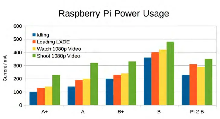
2.3 Chart of Raspberry Pi 2 model B Power Usage 9
2.4 GPIO Pinout Diagram 9
2.5 Infrared Obstacle Detection Sensors 12
2.6 A typical IR sensing circuit 13
2.7 Ultrasonic sensor 14
2.8 Ultrasonic sensor is connected to Raspberry Pi 14
2.10 Servo motor with Raspberry Pi 17
2.11 Logo of Pushover Inventor 17
2.12 API Token/Key 17
2.13 Automatic pet feeder 18
2.14 The Network Structure of WSN Pet feeder 18
2.15 Timed Pet Feeder with Arduino and Servo Motor 18
2.16 Self-replenishing Feeder by Microban 19
2.17 Samples of Automatic Timed Feeders by Different Companies. 20
3.1 Flowchart of project methodology 23
3.2 Block diagram for the pet feeding system 24
3.3 Raspberry Pi 25
3.4 IR sensor 25
3.5 Example of application IR sensor to detect the food 25
3.6 Example simple notification Android 27
3.7 Raspbian’s main window screen and start up menu 28
xiii
4.2 Output window for pet feeder system 31
4.3 Raspberry Pi window screen to open scheduled task 32
4.4 Window Interface to edit scheduled task 33
4.5 Example of code in php file 34
4.6 Interfacing Raspberry Pi with HC-SR04 34
4.7 Interfacing HC-SR04 circuit diagram with Raspberry Pi 35
4.8 Example of script in Python 35
4.9 Ultrasonic sensor at pet feeder 36
4.10 Led of infrared sensor light up when detect food 37
4.11 3D printed “tubemout” connect with servo motor 37
4.12 Tubemount merge with PVC T and 90degree PVC 38
4.13 Tubemout and PVC Twithout 90 degree PVC 38
xiv
LIST OF TABLES
Table Title Pages
2.1 Raspberry Pi's Model 2B Specification 7
2.2
Comparison between Raspberry Pi 3 Model B, Raspberry Pi 2 Model B and
Raspberry Pi Model B+ 8
2.3 Main GPIO connector 10
2.4 Different type of Infrared region 11
4.1 Condition for motor to rotate 39
xv
LIST OF SYMBOLS AND ABBREVIATIONS
A = Ampere
DC = Direct Current
GPIO = General Purpose Input/Output
IDE = Integrated Development Environment
IR = Infrared sensor
OS = Operating System
PWM = Pulse Width Modulation
PC = Personal Computer
PHP = Hypertext Preprocessor
Wi-Fi = Wireless Fidelity
HTML = Hypertext Mark-up Language
I/O = Input and Output
HDMI = High Definition Multimedia Interface
1
CHAPTER 1
INTRODUCTION
1.1 Introduction
This chapter will explain the project with its background, problem statement, objectives, project scope and limitation, project significance and thesis outline.
1.2 Background
In this modern age, people running out of time to complete their daily activities. But, this cannot be reason not to fulfill their responsibility include as a pet owner. Statistic from PFMA (Pet Food Manufacturer’s Association) show that in 2016 it is estimated that 11million (40% of) households have pets. The pet population stands at around 57 million. Cat population is 7.5 million and 17% household with a cat. Automatic feeder for pet is developing to ease the pet owner fulfills their responsibilities to feed their pet at home. They can feed their pet anytime and anywhere by using this system. In this project, Raspberry Pi will be used in the system as a main part and sensors will be used to provide inputs to the Raspberry Pi in order for the system to working. Besides, this automatic feeder makes the pet owner easy to control how much food is given to their pet. This is because suitable amounts of food that will be given to pet depend on the programming of servo motor to control the speed and positioning.
2 most pets eat dry food. The pet owner cannot leave out wet food because it will go bad in the time that pet has to eat it. But with this feeder, all of the food is in an air tight container.
1.3 Problem Statement
Nowadays, almost every family have a pet, even they are busy with their work. Owning a pet in these days are not easy as those pet needs to be take care when the pet owner not at home. Rushing for works and other priority leads to the time constraints in feeding their pet, and having to feed their pet in daily basis becomes a burden to the pet owners. Besides, think about the fact that, the pet owner must be want to make sure their pet gets fed at the same time every day, even when they are not at home. Pets are very accustomed to a schedule, whether their owners realize it or not. The pet owner cannot expect someone else to follow their schedule. Therefore, a new invention has come out as the solution for this problem which is the Automatic feeder for pet using Raspberry Pi. Instead of asking neighbour or friends to feed the pet, now the pet owner can feed their pet every time and everywhere without stepping foot into their home by just click inside of a smartphone app to feed their pet.
1.4 Objectives
The objectives of this project are:
i. To study the behavior of the pet when the automatic system is
implemented at their home.
ii. To develop the automatic system for pet feeder using Raspberry PI.
3 1.5 Scope of projects
The area of the scope for this project is focus on cat at home. This pet feeder only supplies the food and no water. In this project, Raspberry Pi work together with Infra-red sensor to detect the level of food in the bowl. It will prevent the overflow of food in the bowl. Besides, ultrasonic sensors use sonar to determine the distance to an object. Infrared sensor can only tell when an obstacle is within a certain distance (threshold distance). It also cannot be used outside in the sun. Next, like any other computer, the Raspberry Pi also uses an operating system and the “stock” OS is a flavor of Linux called Raspbian. Servo motor will be used to dispense the food into the bowl. After sensor connect with Raspberry PI to send data, the Raspberry PI will be communicate with motor and link to android application, Pushover using internet connection to send notification to user, “Done feed cat”.
1.6 Significant of study
4 1.7 Structure of project
Thesis for this semester cover three chapters and the following is the outline for each chapter in order to understand the project reports.
The first chapter introduces about the project background, objective of the project which needs to be achieved, problem statement of the project, project scope and limitation, and project significance.
The second chapter will explain briefly about literature review .This chapter required to do more research and gather more information about the project such as the theory, method of project that available, and some characteristic of component of hardware or software that used in this project.
The third chapter describes about the project methodology that will be implemented in this project. It explains the process flow of the whole project which can be understood from the flowchart. In this chapter also, will be explain the procedure taken to complete the project which consist the detail development of the project.
The fourth chapter describes about the results and discussion. It will explain the results based on the objectives of the project and also difficulties that faces when finishing these projects.
5
CHAPTER 2
LITERATURE REVIEW
2.1 Introduction
New technologies of an Automatic pet feeder using Raspberry Pi will be implementing to assist pet owner in order to manage their pet. For this chapter, to obtain the idea and information about this project, some research has been studied based on the journals that are related to the scope of this project work and methodology.
2.2 Raspberry Pi
The Raspberry Pi is a credit-card sized computer that helps people of all ages to learn computing in languages like Python and Scratch. It’s proficient of doing almost everything reaching from browsing the internet, playing high-definition video, to word- processing and playing games.
6 2.2.1 History of Raspberry Pi
In 1990s, most of the teenager came for interview had a skill as a programmer compared to nowadays, almost people just know the basic of programming. The idea of Raspberry Pi began in 2006, when a group of people from University of Cambridge’s Computer Laboratory which led by Dr. Eben Upton became worried about the decreased number of the skill students in the Computer Science field.
First idea of the Raspberry Pi was based on the Atmel ATmega644 microcontroller. Its PCB layout and schematics were in public. Dr. Eben Upton were collected a group of teachers, academics and computer fanatics to invent an inexpensive computer whereas Raspberry Pi to encourage children and people outside involved in this field. (Ms. Sejal V. Gawande*, Dr. Prashant R. Deshmukh 2015).
2.2.2 Raspberry Pi 2, Model B
The Raspberry Pi 2, Model B as showed from Figure 2.1 below is the second group of Raspberry Pi. The original of Raspberry Pi 1 Model B+ in February 2015 was replaced by this model. It also has the power consumption to be as low as possible. This single board contains two USB ports, GPIO pin, Ethernet port, Audio/video port, slot for camera, HDMI port, and power-in port.
[image:22.596.137.526.134.304.2]
7 The following lists the Raspberry Pi Model 2 B features in Table 2.1:
Table 2.1: Raspberry Pi’s Model 2B Specification
Operating system Linux
RAM 1Gb
USB port 4 USB ports
Ethernet Socket Yes
Micro SD Card Slot Yes (on underside)
HDMI port Yes
CSI Camera Connector Yes
Dimensions The PCB is 85 x 56 x 17 mm.
Moreover, Raspberry Pi 2 Model B also used ARMv7 processor. The original architecture in BCM2836 is same to BCM2835. The only significant difference is the removal of the ARM1176JZF-S processor and replacement with a quad-core Cortex- A7 cluster.
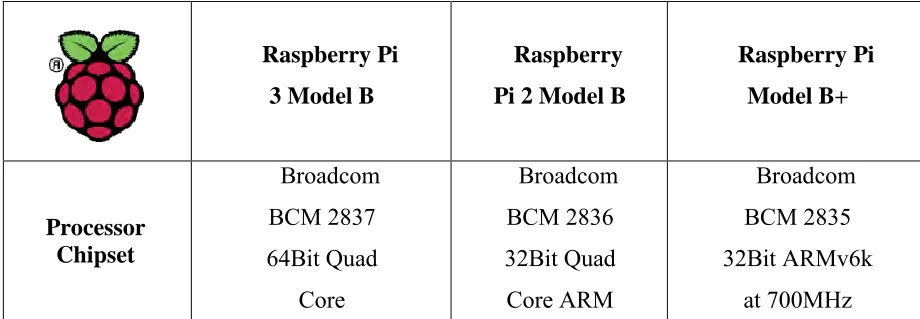
[image:22.596.112.572.583.743.2]2.2.3 Comparison between different Raspberry Pi models
Table 2.2: Comparison between Raspberry Pi 3 Model B, Raspberry Pi 2 Model B and Raspberry Pi Model B+
Raspberry Pi 3 Model B
Raspberry Pi 2 Model B
8 GPU Videocore IV@400MHz Videocore IV@250MHz Videocore IV@250MHz Processor
speed QUAD [email protected]
QUAD Core @ 900MHz
Single Core@700MHz
RAM 1GB SDRAM @
400MHz
1GB SDRAM @400MHz
5.12MB SDRAM@ 400MHz
Storage MicroSD MicroSD MicroSD
USB 2.0 4xUSB Ports 4x USB Ports 4xUSB Ports Max Power
Draw/Voltage 2.5A @5V 1.8A @ 5V 1.8A @ 5V
GPIO 40pin 40pin 40pin
Ethernet Port Yes Yes Yes
WiFi Built in No No
Bluetooth LE Built in No No
Video Output HDMI/Composite via RCA Jack
HDMI/Composite via RCA Jack
HDMI/Composite via RCA Jack
9 2.2.4 Power supply for Raspberry Pi
The power source that a Raspberry Pi uses is a micro USB plug of 5-volt (V) direct current (DC) lines, also shown in Figure 2.2. No data connections are wired to this socket. Hence, any power supply ranging from the smartphone charger to Raspberry Pi’s power supply would be sufficient as long as the output voltage reading meets the specification. It is also noted that the Raspberry Pi kit power supply is rated to 5V 1A, and Raspberry Pi Model 2 B requires a minimum current of 500-700 mA (Liang, 2013) (Norris, 2014).
[image:24.596.136.500.510.708.2]Figure 2.2: 5V micro USB Power Supply