Article
Screening and Selection of Ferric Reducing Bacteria by
Electrical Current for Microbial Fuel Cell
Kamol
Rodyou
1,a,
Sirirat
Rengpipat
2,b,*,
and
Mana
Sriyudthsak
3,c,*1PrograminBiotechnology,FacultyofScience,ChulalongkornUniversity,Bangkok10330,Thailand 2DepartmentofMicrobiology,FacultyofScience,ChulalongkornUniversity,Bangkok10330,Thailand 3DepartmentofElectricalEngineering,FacultyofEngineering,ChulalongkornUniversity,Bangkok10330,
Thailand
E-mail: akrommon@gmail.com,bsrengpipat@gmail.com (Correspondingauthor),cmana.s@chula.ac.th (Correspondingauthor)
Abstract. The efficiency of microbial fuel cell (MFC) performance depends on the competence of microorganisms on being an essential role in primarily converting organic compoundintoelectricity. Inthisstudy,thepossibilityofusingelectricalcurrentto select electrochemicalactivebacteriafromsub-sedimentforuseinMFCwasconducted. Byusing an alternating current (AC) of 0.6-12 mA and selective media, 16 Gram-positive ferric reducing bacteria (GP-FRB), 15Gram-negative ferric reducing bacteria (GN-FRB) and 9 Gram-negative non FRB (GN-nonFRB) were characterized. GN-FRBand GP-FRBwere obtainedfromthecurrentof0.6-6and9-12mA,respectively. AftertestedinMFC,GN-FRB hadagreatercurrentdensityandpowerdensitythanthosefromGN-nonFRBandGP-FRB. However, the greatest voltage was obtained from GP-FRB, followed by those of GN -nonFRBandGN-FRB,respectively. Thehighestcurrentandpowerdensityof13.33mA/m2
and0.32mW/m2,respectivelywerefromGN-FRBnamelyKL14whichwasidentifiedlateras
Proteussp. Thisresearchcouldcontributeapromisingmethodforscreeningandselectionof
ferricreducingbacteriausingelectricalcurrent. MFCinoculatedwithourselectedbacteria couldbeamodelfornextstudyinwastewatertreatment.
Keywords:Ferricreducingbacteria,microbialfuelcell,electricalcurrentselection.
ENGINEERING JOURNAL Volume 21 Issue 5
1.
Introduction
Microbial fuel cells (MFC) are the future trend of wastewater treatment technology which not only reproduce water but also generate electricity simultaneously. MFC can directly convert organic substances in wastewater into electricity by catalytic activity of microorganisms [1]. They oxidize organic substances and extracellular electron transfer (EET) to anode of MFC; consequently, electricity is generated by the flow of electron from anode across circuit to cathode. Electrical current of MFC depends on the efficiency of microorganisms to extracellularly transfer electron to anode [2]. In general metabolic pathway of microorganisms, electron transferred to oxygen as a main electron acceptor to generate ATP by oxidative phosphorylation, but there are groups of bacteria that could transfer electron to electron acceptor outside the cell. According to the metabolism of ferric reducing bacteria (FRB) in anoxic environment they will seek for another electron acceptor other than oxygen to complete its electron transport chain. Their electron will extracellularly transfer to soluble Fe(III) and insoluble Fe(III) oxide in anoxic sediment [3-4]. Whereas, in anoxic anodic compartment, FRB such as Shewanella putrefaciens can oxidize organic substances and efficiently transfer electron to anode [5]. Additionally, electrochemical activity of bacterial cell is an important concern for EET and determine also the ability of cell to transfer to anode. Only S. putrefaciens in anoxic but not in aerobic culture has an electrochemical activity and efficiently transfer electron to anode [6]. More extensive studies found in Geobacter spp. and Shewanella spp. that their electron can export out of the cell via cytochrome and pili to anode in anoxic condition [7]. The other mechanism of EET is self-mediated electron transfer which transfer electron to anode by redox compounds as electron shuttle between cell and anode. This occurred by self-secreted mediator bacteria such as Ps. aeruginosa which can transfer electron to anode by its pyocyanin compound [8-9]. Selection of electrochemical active bacteria (EAB) are capable of performing wastewater treatment and have effective EET, therefore should be selected and their potential will be suitable for use in MFC.
EAB could be isolated from anoxic environment or from anodic biofilm of wastewater feeding MFC. In anoxic sediment, Geobacter spp. and Shewanella spp. which are dominant genera of FRB were isolated by using Fe(III) oxide as electron acceptor and using acetate and lactate as electron donor, respectively [5, 10-11]. In addition, Rhodoferax ferrireducens, a psychrotolerant FRB isolated from sea-sediments could directly utilize glucose to electricity in MFC [12-13]. EAB such as Clostridium butyricum [14], Aeromonas hydrophila [15],
Rhodopseudomonas palustris [16], and Orchrobactrum anthropi [17] were isolated from anodic biofilm of MFC.
Dominant bacterial species in biofilm depend on source of wastewater feeding into anodic compartment of MFC [18-19]. After MFC fed with wastewater for long periods, mix bacterial communities will form biofilm on anode and these biofilms are responsible for electron transfer to electrode while treating wastewater [20-22]. In addition, EAB selection by electric potential was demonstrated to be possible. Poising electrical potential at anode was applied in benthic microbial fuel cell (BMFC) for facilitating EET of bacteria in sediment attaching on electrode thoroughly [23]. Poised potential can reduce lag time of the pure culture and mix consortium in producing current; however, there is no difference in the maximum current output [24-25]. Furthermore, negative poised potential (V vs a standard hydrogen electrode, SHE) are useful to enrich Geobacter sulfurreducens on anode [26]. Moreover, direct current (DC) was also claimed to be used to select EAB for use as inoculums in anodic compartment of MFC [27].
Based on natural selection, the bacteria survive in selective pressure will have higher performance. In other words, they have to survive during current flow in and out of the cells. Hence, we expect that the bacteria survive under current biasing should have higher (electrochemical) performance than the others. Therefore, in this research, a constant alternating current (AC) poising on stainless-steel electrode will be used to select the electrochemically active microorganisms from sea sediment. To characterize the electrochemical performance, ferric reduction activity will be studied. Our selected microorganism should facilitate electron flow towards the electrode and will be used in MFC practicably.
2.
Materials
and
Methods
2.1. Screening and Selection of Ferric Reducing Bacteria
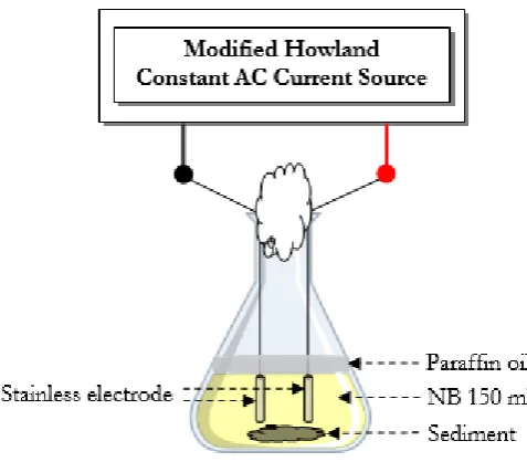
couple of stainless steel (316L) electrode with the surface area of 7.1 cm2 was put into the flask. It was used
as stimulating electrode. Then paraffin oil was added as a top layer in order to generate an anaerobic condition. Subsequently, the 50 Hz AC generator from a laboratory-made current source was applied to the stainless steel electrode. To investigate the effect of the current, the amplitude of the current was varied from 0.6, 3, 6, 9 and 12 mA (or 0.084, 0.42, 0.84, 1.27 and 1.69 mA/cm2). After incubation for 5 days,
electrodes were transferred into the new 250 ml flask contained 150 ml of NB covered with paraffin oil as indicated in Fig. 1. The biofilm coated electrode was incubated under the same electrical current selection for another 5 days. The same procedure was carried out every 5 days for 30 days. After incubation in alternating current for 5th transferring (30 days), the biofilm on the electrode was spread on NA and NA
with 20 mmol/l of ferric citrate. It was incubated in anaerobic chamber, GENbox anaer (bioMérieux, France), at room temperature for 5-7 days. Mixed bacterial colonies were restreaked until pure culture was isolated. Pure cultures of selected bacteria were streaked on NA supplemented with 20 mmol/l ferric citrate, and incubated in anaerobic chamber, GENbox anaer, at room temperature for 5-7 days. The color change on NA due to ferric citrate from the reddish-brown color into the light-green color was used to evaluate the ferric reduction activity.
Fig. 1. Schematic diagram of experimental set up of AC electric current selection in flask.
2.2. Construction and Configuration of MFC
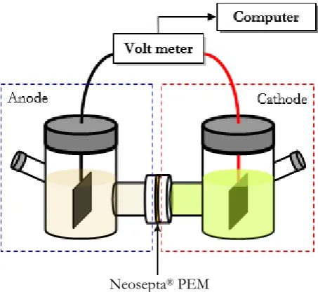
Dual glass chamber MFC was designed and used in this research. Neosepta® PEM (model CMS, ASTOM
corporation, Japan), with 3 cm in diameter, functioning as cation exchange membrane, was installed between the anodic and cathodic compartment as illustrated in Fig. 2. It was sterilized by autoclaving at 110ºC for 15 min before use. Carbon fiber cloth (ACELAN, Korea) with surface area of 18 cm2, was used
as anode and cathode. Electrode was installed inside the bottle and sterilized by autoclaving at 121ºC for 15 min.
2.3. Microbial Fuel Cell Set-Up and Experiment
Phosphate buffer (K-buffer 100 mmol/l, pH 7.0) as electrically conductive medium was added into anodic and cathodic compartment, 100 mmol/l glucose as electron donor, and 1 mmol/l potassium ferric cyanide [K3Fe(CN)6] as electron acceptor, were added into anodic and cathodic compartment, respectively.
Microorganism concentration of 108-109 CFU/ml was added into anodic compartment. All solutions were
sterilized by autoclaving at 121ºC for 15 min before use.
[image:3.595.175.414.281.490.2]remaining medium broth. Cell pellet was resuspended into phosphate buffer for using as biological catalyst in the anodic compartment of MFC.
Neosepta® PEM
Fig. 2. Schematic diagram of experimental set up of dual chamber MFC.
2.4. MFC Outputs Measurement and Calculation
MFC performances were evaluated in term of voltage, current density and power density that was supplied to external load or resistance. MFC was connected to pico ADC-11 data acquisition unit (Pico technology, UK). Voltage was recorded every 15 seconds and transferred to the personal computer via parallel port. The output voltage was displayed in pico recorder and pico player program (Pico technology, UK). The open circuit voltage (OCV) was obtained when the system was not connected to any load or resistance. The voltage output was measured at steady state after the external resistor (R) was connected. Resistor in the range of 1-100 kΩ, were used to investigate the performance. The current density (i) (mA/m2) and power
density (P)(mW/m2) were calculated using Eq. (1) and Eq. (2), respectively, where Vis the voltage (volts)
and A is electrode surface area (m2).
i = (V/R)/A (1)
P = (IV)/A (2)
2.5. Identification of Bacterial Isolates
Bacterial cell morphology and Gram staining were observed using light microscopy at x1000 magnification. Biochemical tests were examined by using rapid identification kit API® 20E (bioMérieux, France). All the
protocols are carried out followed the company direction. Results from API kit were interpreted by using program API®WEB. Bacterial DNA was extracted from bacterial grown in tryptic soy broth (TSB) at 37C,
24 h by using Simax Genome DNA Extraction Kit (Beijing SBS Genetech Co., Ltd., China). DNA extraction was performed following the manufacturer’s instructions manual. 16S rDNA was amplified by polymerase chain reaction (PCR) (94C for 1 min, 55C for 1 min, 72C for 2 min, 35 cycles using primers 16F27 (5’-AGA GTT TGA TCC TGG CTC AG-3’) and 16R1522 (5’-AAG GAG GTG ATC CAG CCG CA-3’) as described in [28]. PCR products were sequenced at Macrogen Inc. co. Ltd. (Seoul, Korea). The 16S rDNA sequences were analysed using BIOEDIT and GenBank® nucleotide data base.
2.6. Statistical Analysis
[image:4.595.184.411.124.332.2]vs. GN-nonFRB, respectively. The differences of means between two-sample for variances were compared by F-test and T-test, using the accepting significance at the p < 0.05 level.
3.
Results
and
Discussion
3.1. Bacterial Isolation from Sea-Sediments of Ko Lan
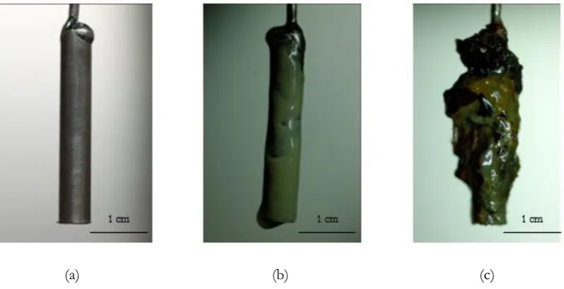
After sea-sediments from Ko Lan were selected by AC for 30 days, microbial biofilm was observed only at anode electrode stimulating at 6, 9 and 12 mA. Biofilm formation on electrode for bacteria selection using different AC was shown in Fig. 3. The pure culture of 40 isolates of biofilm from the sea-sediments were isolated and designated as KL1-40. All isolates were characterized based on Gram staining, cell morphology under microscopic examination. They were 16 Gram-positive bacteria (GPB) and 24 Gram-negative bacteria (GNB).
(a) (b) (c)
Fig. 3. Biofilm formation on electrode for bacteria selection using AC current (a) before supplied current (b) 6 mA and (c) 12 mA after 30 days.
3.2. Ferric Reduction of Isolates
Ferric reduction activity of all isolates was characterized under anaerobic condition by streaking pure cultures on NA plates containing ferric citrate. FRB could use Fe(III) as the electron acceptor under the anaerobic condition, thus Fe(III) were reduced to be Fe(II). FRB changed the reddish-brown color of NA with ferric citrate into the light green-color. A total of 40 isolates comprised of 16 Gram-positive FRB (GP-FRB), 15 Gram-negative FRB (GN-(GP-FRB), and 9 Gram-negative non FRB (GN-nonFRB) were identified and kept in anaerobic chamber for further study.
3.3. MFC Performance from Various Isolates
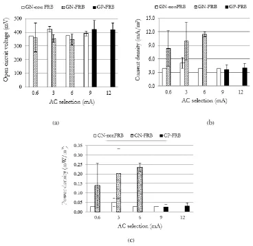
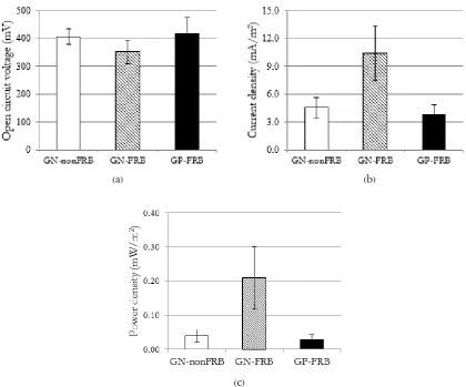
The current density and power density were determined by connecting the various external resistors, ranging from 1 to 100 kΩ, across the anode and cathode. However, to compare the current density and power density of the 40 isolates the same load of 1 kΩ was connected to the MFC. The results were shown in Fig. 4. After individual isolate of GP-FRB, GN-FRB and GN-nonFRB was performed in MFC. It was found that the maximum open circuit voltage (Vmax) of the 40 isolates were in the range of ~300-500 mV with no significant difference (p > 0.05) as shown in Fig. 4(a), whereas the highest Vmax ~500 mV was produced by GP-FRB. Average current density from GP-FRB and GN-nonFRB (less than 6 mA/m2) were
different from the one of GN-FRB (~8-12 mA/m2) significantly (P < 0.05) (Fig. 4(b)). The power density
of the GP-FRB and GN-nonFRB were less than 0.05 mW/m2 while the GN-FRB gave the highest average
[image:5.595.100.499.257.461.2]difference at P < 0.05. This indicates that for the same ferric reducing capability, the GN-FRB offers the higher performance than the GP-FRB. Concurrently, the same higher performance can be obtained from GNB that having ferric reducing capability than those without ferric reducing capability significantly different at P < 0.05. The highest current and power density was 13.33 mA/m2 and 0.32 mW/m2,
respectively obtained from GN-FRB, KL14 isolate.
(a) (b)
(c)
Fig. 4. AC selection (mA) and MFC performance of the 40 isolates in sea-sediments from Ko Lan: Gram negative–non ferric reducing bacteria non FRB) (n= 9), Gram negative-ferric reducing bacteria (GN-FRB) (n= 15) and Gram positive-ferric reducing bacteria (GP-(GN-FRB) (n=16). (a) open circuit voltage, (b) current density at 1 kΩ load, and (c) power density at 1 kΩ load.
3.4. Stimulating Current and Bacterial Type
[image:6.595.112.481.151.509.2]3.5. Open circuit Voltage, Current Density and Power Density
The open circuit voltage in our experiment is the voltage obtained at open circuit condition without any load connection. This value indicates the potential of the MFC that how much it can distribute power to the load. However the real power that the MFC could distribute depending on many conditions or parameters. The high OCV-MFCs may distribute power lower than the low OCV-MFCs if their internal impedances are higher than the low OCV-ones. Therefore, we had to measure the OCV before connecting our MFCs to the load. In our cases, we found that the open circuit voltage of all MFCs were quite similar; however, the current and power density were significantly varied when the resistor load was added. The lower current and power means there is more loss inside the MFCs due to the internal impedance. This implies that the internal resistance of the MFCs play a very important role in the MFCs performances. The average of open circuit voltage, current density and power density among GN-nonFRB (n=9), GN-FRB (n=15) and GP-FRB (n=16) are indicated in Fig. 5. It is obvious that the high open circuit voltage was obtained from the GP-FRB (Fig. 5(a)), while the highest of both current density (Fig. 5(b)) and power density (Fig. 5(c)) were obtained from the GN-FRB. This indicates that the ferric reducing capability plays important impact on the MFC performance.
(a) (b)
[image:7.595.87.508.304.653.2](c)
Fig. 5. Averageandstandarddeviationof(a) open circuit voltage, (b) current density at 1 kΩ load and (c) power density at 1 kΩ load of each type of bacteria: GP-FRB (n=16), GN-non FRB (n=9) and GN-FRB (n=15).
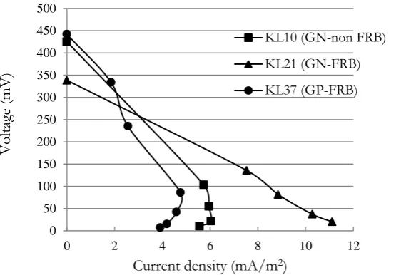
3.6. Voltage-Current Density Characteristics
the lowest. The largest slope of voltage and current density observed from the GP-FRB (KL37) indicates that it possesses the largest ohmic loss than those from GN-FRB (KL21) and GN-nonFRB (KL10). Ouitrakul et al. have shown that the impedance of the electrode used in the MFC do effect the performance of MFC [30]. For our cases, all parameters used in forming MFC were the same, except for the microorganism used. Then it can be mentioned that the difference in impedance comes from the difference of the cell. The internal impedance of each MFC could be estimated from the slope (Fig. 6). It was found that the internal impedance of the GP-FRB, GN-nonFRB and GN-FRB were 70, 57 and 30 kΩ, respectively. It could be explained from the fact that most of the GPB has the different compositions of cell wall especially more peptidoglycan thicker than the one of GNB. This made the impedance of the GPB cell wall to be higher than the GNB one. It is believed that this impede the electron transfer from the inside of the cell to the electrode. That is why the voltage drop of the GP-FRB was higher than the GN-nonFRB and GN-FRB. It should be noted that the internal impedance of GP-FRB was more than 2 times of the one from GN-FRB.
Moreover it should also be mentioned that the internal impedance of the GN-nonFRB was two times higher than the one from GN-FRB. This implies that the ohmic loss of the GN-FRB was lesser than the GN-nonFRB. GN-FRB clearly generated higher current density and higher electron capability than those of GN-nonFRB. These results are consistent with previous report that GN-nonFRB such as E. coli can poorly transfer electron to electrode, and it required electron mediator for facilitating their electron transfer to the electrode [31]. It is possible to indicate that the ferric reducing capability also plays important role in the electron transfer from cell to electrode. Moreover, many researchers also succeeded in enhancing electron transport of GN-nonFRB by modifying anode electrode [32-33]. Hence, GN-FRB from this study shows the highest performance in current density and power density among all three bacterial groups.
Fig. 6. Typical voltage and current density relation of GP-FRB (KL37), non FRB (KL10), and GN-FRB (KL21).
3.7. Identification of Electrical Current Enriched Bacteria
Only KL11, KL14 and KL22 were identified. They are GNB with unique swarm colonies on agar plates. Using API 20E kit (BioMérieux, France) and program API®WEB (bioMérieux, France), KL11, KL14 and
KL22 were primarily identified as Proteus sp. and Proteus vulgaris, respectively. The identity percentage of KL11, KL14 and KL22 were 96%, 97.7%, and 99.6%, respectively. Comply with BioEdit (Ibis Biosciences, California, USA) the 16S rDNA sequence of KL11, KL14 and KL22 was 1508, 1512, and 1513 bp, respectively. After compared with 16S rDNA sequence from database GenBank using the nucleotide-nucleotide Blast (BLASTN) program (www.ncbi.nlm.nih.gov/blast/), KL11, KL14 showed 99% similarity
to Proteus sp. (accession number EF426445.1 and EF426446.1, consecutively) and 98% similarity to Proteus
vulgaris for KL22 (accession number DQ499636.1). Three isolates belongs to the family Enterobacteriaceae
which are fermentative and facultative anaerobic GNB. 16s rDNA sequence of KL11, KL14 and KL22 was 0 50 100 150 200 250 300 350 400 450 500
0 2 4 6 8 10 12
V
oltag
e (mV)
Current density (mA/m2)
[image:8.595.158.450.373.566.2]submitted to GenBank data base and acquired accession number KP313867, KP313868, and KP313869, respectively.
Proteus sp. had previously been used in MFC but the anode electrode of MFC was modified and
mediator (thionin) was added in order to facilitate electron transfer of bacterial cell [34]. We hardly compared the outputs even with the same genus of bacteria was used. The mechanism of electron transfer
of Proteus sp. to electrode was still unclear. However, further improvement by optimizing the physical and
chemical parameters in MFC is required.
4.
Conclusion
In this study, AC current was used to select bacteria from sub-sediment. Our 40 isolates were classified into three groups, GN-non FRB, GN-FRB and GP-FRB. The GNB were obtained at a low current in the range of 0.6-6 mA while the GPB did at the higher current of 9-12 mA. The results show feasibility in using current in selection or classification the type of bacteria. MFC outputs of GN-FRB generated greater current density and power density than GN-non FRB and FRB, respectively. On the other hand, GP-FRB had greater open circuit voltage than GN-non GP-FRB and GN-GP-FRB, respectively. The results can be explained from the fact that GNB cell wall have thinner peptidoglycan layer than GPB or there are the difference in cell wall composition which lead to the lower voltage drop or lowering the ohmic loss at the cell, so GNB have electron transfer better than GPB. Moreover, it was also found that FRB have better electron transfer than non-FRB resulting in the higher current density and power density. It implies that the ferric reducing activities are also the one of key parameter in forming MFC. The results indicate that the GN-FRB should be used in construction of MFC due to the better electron transfer and lower the ohmic loss at the cell. It should be noted that our isolates are Proteus spp. It is interesting that these bacteria can be applied to form MFC without using any electron mediator. Moreover, the GN-non FRB can produce electricity higher than the GP-FRB, even it has no ferric reducing activities. Further study should be investigated to understand the detail mechanism of electrical current on the bacterial growth.
Acknowledgements
This research was financially supported by a Chulalongkorn University Graduate Scholarship to Commemorate the 72nd Anniversary of His Majesty King Bhumibol Adulyadej, a CU Graduate School
Thesis Grant from Chulalongkorn University, and the 90th Anniversary of the Chulalongkorn University
fund (Ratchadaphisek Somphot Endowment Fund).
References
[1] M. C. Potter, “Electrical effects accompanying the decomposition of organic compounds,” Proc. R. Soc.
Lond. B., vol. 84, no. 571, pp. 260-276, Sep. 1911.
[2] U. Schröder, F. Harnisch, and L. T. Angenent, “Microbial electrochemistry and technology: terminology and classification,” Energy Environ. Sci., vol. 8, no. 2, pp. 513-519, Feb. 2015.
[3] D. R. Lovley, and E. J. P. Phillips, “Organic matter mineralization with reduction with reduction of ferric iron in anaerobic sediments,” Appl. Environ. Microbiol., vol. 51, no. 4, pp. 683-689, Apr. 1986. [4] K. H. Nealson, and D. Saffarini, “Iron and manganese in anaerobic respiration: environmental
significance, physiology, and regulation,” Annu. Rev. Microbiol., vol. 48, pp. 311-343, Oct. 1994.
[5] B. H. Kim, H. J. Kim, M. S. Hyun, and D. H. Park, “Direct electrode reaction of Fe(III)-reducing bacterium, Shewanella putrefaciens,” J. Microbiol. Biotechnol., vol. 9, no. 2, pp. 127-131, Apr. 1999.
[6] H. J. Kim, H. S. Park, M. S. Hyun, I. S. Chang, M. Kim, and B. H. Kim, “A mediator-less microbial fuel cell using a metal reducing bacterium, Shewanellaputrefaciens,” Enzyme Microbiol. Technol., vol. 30, no. 2, pp. 145-152, Feb. 2002.
[7] A. Sydow, T. Krieg, F. Mayer, J. Schrader, and D. Holtmann, “Electroactive bacteria—molecular mechanisms and genetic tools,” Appl. Microbiol. Biotechnol., vol. 98, no. 20, pp. 8481-8495, Oct. 2014. [8] K. Rabaey, N. Boon, S. D. Siciliano, M. Verhaege, and W. Verstraete, “Biofuel cells select for
[9] K. Rabaey, N. Boon, M. Höfte, and W. Verstraete, “Microbial phenazine production enhances electron transfer in biofuel cells,” Environ. Sci. Technol., vol. 39, no. 9, pp. 3401-3408, May 2005.
[10] D. R. Bond, and D. R. Lovley, “Electricity production by Geobacter sulfurreducens attached to electrodes,” Appl. Environ. Microbiol.,vol. 69, no. 3. pp. 1548-1555, Mar. 2003.
[11] D. R. Lovley, “Bug juice: harvesting electricity with microorganisms,” Nat. Rev. Microbiol., vol. 4, no. 7, pp. 497-508, Jul. 2006.
[12] S. K. Chaudhuri, and D. R. Lovley, “Electricity generation by direct oxidation of glucose in mediatorless microbial fuel cells,” Nat. Biotechnol., vol. 21, no. 10, pp. 1229-1232, Oct. 2003.
[13] K. T. Finneran, C. V. Johnsen, and D. R. Lovley, “Rhodoferax ferrireducens sp. nov., a psychrotolerant, facultatively anaerobic bacterium that oxidizes acetate with the reduction of Fe(III),” Int. J. Syst. Evol.
Microbiol., vol. 53, no. 3, pp. 669-673, May 2003.
[14] H. S. Park, B. H. Kim, H. S. Kim, H. J. Kim, G. T. Kim, M. Kim, I. S. Chang, Y. K. Park, and H. I. Chang, “A novel electrochemically active and Fe(III)-reducing bacterium phylogenetically related to
Clostridium butyricum isolated from a microbial fuel cell,” Anaerobe,vol. 7, no. 6, pp. 297-306, Dec. 2001.
[15] C. A. Pham, S. J. Jung, N. T. Phung, J. Lee, I. S. Chang, B. H. Kim, H. Yi, and J. Chun, “A novel electrochemically active and Fe(III)-reducing bacterium phylogenetically related to Aeromonas hydrophila
isolated from a microbial fuel cell,” FEMS Microbiol. Lett.,vol. 223, no. 1, pp. 129-134, Jun. 2003. [16] D. Xing, Y. Zuo, S. Cheng, J. M. Regan, and B. E. Logan, “Electricity generation by Rhodopseudomonas
palustris DX-1,” Environ. Sci. Technol., vol. 42, no. 11, pp. 4146-4151, Jun. 2008.
[17] Y. Zuo, D. Xing, J. M. Regan, and B. E. Logan, “Isolation of the exoelectrogenic bacterium
Ochrobactrum anthropi YZ-1 by using a U-tube microbial fuel cell,” Appl. Environ. Microbiol., vol. 74, no.
10, pp. 3130–3137, May 2008.
[18] D. Pant, G. Van Bogaert, L. Diels, and K. Vanbroekhoven, “A review of the substrates used in microbial fuel cells (MFCs) for sustainable energy production,” Bioresour. Technol., vol. 101, no. 6, pp. 1533-1543, Mar., 2010.
[19] P. D. Kiely, R. Cusick, D. F. Call, P. A. Selembo, J. M. Regan, and B. E. Logan, “Anode microbial communities produced by changing from microbial fuel cell to microbial electrolysis cell operation using two different wastewaters,” Bioresour. Technol., vol. 102, no. 1, pp. 388-394, Jan. 2011.
[20] B. E. Logan, “Simultaneous wastewater treatment and biological electricity generation,” Water Sci.
Technol., vol. 52, no. 1-2, pp. 31-37, Jan. 2005.
[21] B. E. Logan, B. Hamelers, R. Rozendal, U. Schröder, J. Keller, S. Freguia, P. Aelterman, W. Verstraete, and K. Rabaey, “Microbial fuel cells: Methodology and technology,” Environ. Sci. Tehnol., vol. 40, no. 17, pp. 5181-5192, Jul. 2006.
[22] J. C. Biffinger, J. Pietron, R. Ray, B. Little, and B. R. Ringeisen, “A biofilm enhanced miniature microbial fuel cell using Shewanella oneidensis DSP10 and oxygen reduction cathodes,” Biosens. Bioelectron., vol. 22, no. 8, pp. 1672-1679, Mar. 2007.
[23] D. A. Finkelstein, L. M. Tender, and J. G. Zeikus, “Effect of electrode potential on electrode-reducing microbiota,” Environ. Sci. Technol., vol. 40, no. 22, pp. 6990-6995, Oct. 2006.
[24] E. J. Cho, and A. D Ellington, “Optimization of the biological component of a bioelectrochemical cell,” Bioelectrochem.,vol. 70, no. 1, pp. 165-172, Jan. 2007.
[25] X. Wang, Y. Feng, N. Ren, H. Wang, H. Lee, N. Li, and Q. Zhao, “Accelerated start-up of two-chambered microbial fuel cells: Effect of anodic positive poised potential,” Electrochim. Acta, vol. 54, no. 3, pp. 1109-1114, Jan. 2009.
[26] H. S. Lee, C. I. Torres, and B. E. Rittmann, “Effects of substrate diffusion and anode potential on kinetic parameters for anode-respiring bacteria,” Environ. Sci. Technol., vol. 43, no. 19, pp. 7571-7577, Oct. 2009.
[27] H. J. Lin, X. Wu, C. Miller, and J. Zhu, “Improved performance of microbial fuel cells enriched with natural microbial inocula and treated by electric current,” Biomass Bioenerg., vol. 54, pp. 170-180, Jul. 2013.
[28] A. Bayane, D. Roblain, R. D. Dauphin, J. Destain, B. Diawara, and P. Thonart, “Assessment of the physiological and biochemical characterization of a Lactic acid bacterium isolated from chicken faeces in sahelian region,” Afr. J. Biotechnol., vol. 5, no. 8, pp. 629-634, Apr. 2006.
[30] S. Ouitrakul, M. Sriyudthsak, S. Charojrochkul, and T. Kakizono, “Impedance analysis of bio-fuel cell electrodes,” Biosens. Bioelectron., vol. 23, no. 5, pp. 721-727, Dec. 2007.
[31] D. H. Park and J. G. Zeikus, “Electricity generation in microbial fuel cells using neutral red as an electronophore,” Appl. Environ. Microbiol.,vol. 66, no. 4, pp. 1292-1297, Apr. 2000.
[32] U. Schröder, J. Nießen, and F. Scholz, “A generation of microbial fuel cells with current outputs boosted by more than one order of magnitude,” Angew. Chem. Int. Ed. Engl., vol. 42, no. 25, pp. 2880-2883, Jun. 2003.
[33] T. Zhang, Y. Zeng, S. Chen, X. Ai, and H. Yang, “Improved performances of E. coli-catalyzed microbial fuel cells with composite graphite/PTFE anodes,” Electrochem. Commun., vol. 9, no. 3, pp. 349-353, Mar. 2007.