
This is a repository copy of
Behaviour of Restrained Steel Beam with Reduced Beam
Section Exposed to Fire
.
White Rose Research Online URL for this paper:
http://eprints.whiterose.ac.uk/98683/
Version: Accepted Version
Article:
Guo, Z. and Huang, S. orcid.org/0000-0003-2816-7104 (2016) Behaviour of Restrained
Steel Beam with Reduced Beam Section Exposed to Fire. Journal of Constructional Steel
Research, 122. pp. 434-444. ISSN 0143-974X
https://doi.org/10.1016/j.jcsr.2016.04.013
[email protected] https://eprints.whiterose.ac.uk/ Reuse
This article is distributed under the terms of the Creative Commons Attribution-NonCommercial-NoDerivs (CC BY-NC-ND) licence. This licence only allows you to download this work and share it with others as long as you credit the authors, but you can’t change the article in any way or use it commercially. More
information and the full terms of the licence here: https://creativecommons.org/licenses/
Takedown
If you consider content in White Rose Research Online to be in breach of UK law, please notify us by
1
Behaviour of Restrained Steel Beam with Reduced Beam Section Exposed to Fire
Zhen Guoa*, Shan-Shan Huangb
a
School of Mechanics & Civil Engineering, China University of Mining and Technology, Xu zhou 221116, China
b
Department of Civil & Structural Engineering, The University of Sheffield, Sir Frederick Mappin Building, Mappin Street, Sheffield S1 3JD, UK
Abstract
Reduced beam section (RBS) is one of the connection types, which is economical and popular for use in steel moment frames in seismic regions. By cutting some portions of the beam flanges near the column face, the RBS connections are designed to form plastic hinge within the RBS zone so that it could enhance the structural seismic performance. However, the steel beams with RBS connections have to provide robustness when exposed to fire. Although the responses of ordinary steel beams to elevated temperatures have been investigated over the last few decades, there has been very limited research on the behaviour of steel beams, with RBS connections in fire. This study includes a series of numerical analysis, to investigate the high-temperature performance of steel beams with RBS connections, compared to the responses of ordinary steel beams to fire. Various parameters have been considered, including the types of fire curves, the levels of beam-end restraints and the cutting profiles of the RBS connections. Overall, the deformation shape of RBS beams at high temperature is similar to that of ordinary steel beams, whereas the RBS beams could have longer period of fire resistance. The cut section actually provides both rotational and axial
ductility/deformability to the connection, enhancing its fire resistance. Moreover, the cutting length, proposed by EC8, is also adequate for fire design. The minimum distance, between the RBS zone and the beam-end, proposed by FEMA-350 has been shown sufficient.
Keywords: Reduced Beam Section (RBS); Steel Connections; Fire; Moment Frame.
*
Corresponding author: Tel.:+86 516 83590666; fax: +86 516 83884360
2
1. Introduction
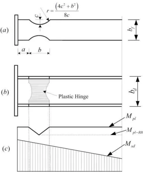
After the 1994 Northridge[1] and 1995 Kobe earthquakes [2], the reduced beam section (RBS) joints have been extensively used in steel moment resisting frames (MRFs) to avoid brittle fractures of beam-to-column connections as observed in these two hazards [3]. The RBS joints, with portion of beam flanges near beam-to-column connections being cut[4], are designed to form a plastic hinge away from a connection so that beams (rather than the beam-to-column interface) could develop ductility, as shown in Fig.1. In this figure, Msdis the design bending moment; Mpl is the cross- sectional bending resistance; andMpl-RBS is the sectional plastic moment resistance at RBS zone. As indicated by several quasi-static tests [5] [6], RBS has excellent energy dissipation capacities under cyclic loads, in terms of forming plastic hinge in the RBS zone and protecting the connection and the connected elements.
The design requirements of connection for fire[7] and that for earthquake [8-10] are very different. In seismic design, it is required that a plastic hinge is formed at the RBS zone to provide sufficient rotational ductility. However, for fire design, connections need to be able to resist very high forces along the axis of the beam; either large compression due to restrained thermal expansion during initial heating or large tension due to the very large beam deflection in the catenary tension phase [11]. The RBS beams, with the flanges cut to provide ductility required by seismic design, may have lower flexural and tensile capacities and poorer fire performance than those of ordinary beams. However, there has been very limited research on the fire resistance of RBS beams, which is worth investigating.
3
the RBS zone and the beam-end restraints on the fire resistance of RBS joint have not been investigated. The beam-end restraints (both rotational and axial) will affect the internal force distribution and hence affect the behaviour of connection, whereas this effect needs to be quantified.
This paper presents an investigation on RBS beams, considering the effects of geometrical size of RBS, beam-end restraint and fire temperature-time relationship, on the high-temperature
performance of RBS beam at elevated temperatures. The robustness of RBS connections in fire is the main concern of this research, and so more attention has been put on to the fracture
time/temperature rather than on the ultimate load/moment capacities. The effects of the supported concrete slab on the temperature distribution in the connection and beam, have also been taken into account.
2. High-temperature performance of ordinary steel beam in fire
The high-temperature performance of ordinary steel beams has been studied widely in the world over the last few decades [16][17]. This section summarizes typical behaviour of ordinary (non-RBS) steel beams in fire.
2.1 Structural damage of steel beams in fire tests
4
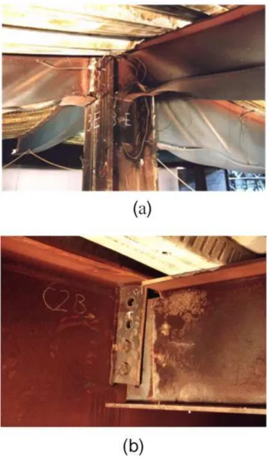
compressive stresses at the beam-ends. Furthermore, the demand of beam-to-column connections is still important to the structural fire safety. Fig.2 (b) shows the connection failure in Cardington fire test (British Steel Test 2: Plane frame test) [18]. The connected plate or the bolt fracture is usually the major failure mode for beams in fire[19]. It means that the beam-end of the ordinary beam is the key zone of bearing higher combination of fire-induced fires and is the weakened section during the structures exposed to fire.
2.2 Fire-induced internal forces
In ambient-temperature design, steel beams are designed to resist bending moment and shear. In fire, a steel beam experiences completely different loading (large axial forces and bending moments), as well as large deflections. Axial compression and bending moments can be caused by the restraint to thermal expansion and thermal bowling; axial tension and bending moments can be resulted from the large deflection of the beam, due to the degradation of mechanical properties of steel at high-temperatures.
Subject to fire, the axial forces in an axially restrained beam usually undergo three stages, as shown in Fig.3 [20]. During initial heating (shown as the Thermal Expansion Phase in this figure), the beam expands (or intends to expand) because of continuous heating, producing an additional compressive axial force and bending moment due to the effect of end-restraints. Hence, the connected elements (column and connection) could experience large deformation or fracture, causing progressive whole building collapse, as exemplified by the collapse of the World Trade 7th building [21] in the New York City. As illustrated in Fig. 3, the compression starts to decrease (Quasi-Catenary Phase in this figure, starting from Ta), as the beam softens and deflects with increasing temperature. The
5
The mid-span deflection limit, span/20, given in EC3 [22], is sometimes used as a ‘failure’ criterion when evaluating the safety and fire resistance of steel beams, in particular in structural fire engineering analytical design. In fire, the increase in beam deflection is mainly caused by the
reduced beam stiffness and strength. When steel temperature is high enough, the flexural resistance of the beam falls below the applied load; tensile fracture could initiate from either the bottom flange of the mid-span of the beam or at the beam-to-column connections[23].
3. Performance of RBS beam in fire
For H-section universal beams, the bending resistance is mainly provided by flanges (the web mainly provides shear resistance). In fire, the whole cross-section of the beam is required to bear the compression during the Thermal Expansion Phase (as illustrated in Fig. 3) as well as tension during the Catenary Action Phase. Additionally, the beam-ends also need to resist the bending moments caused by beam deflection (resulted from the loss of flexural stiffness at high temperature and from thermal deflections).
However, the behaviour of RBS beams, when exposed to fire, may be very different from that of ordinary beams. The RBS zone has significantly lower stiffness than that of the rest of the beam; therefore, it usually experiences high stress concentration. The response of the weakened RBS region to the additional internal forces induced by fire, as addressed in Section 2.2, could be very different from that of a normal beam. This has not been systematically investigated and a numerical study on this is presented in this paper.
3.1 High-temperature FEA structural analysis
6
dimensions of the RBS zone of this control model were determined according to EC8 [8]. The design requirements given by FEMA-350[9] were employed for the parametric study on RBS-zone
dimensions. Table 1 summarizes the design recommendations on RBS dimensions given by EC8 and FEMA-350.
The physical loading, 64.7kN (load ratio = 0.5; referred as LR5 hereafter) was adopted. The load ratio is defined as the ratio of applied bending moment to the bending moment resistance of the beam at ambient temperature.
3.1.1 Model setup
The axial and rotational restraints provided by the columns to the beam-ends were modelled by the 1D linear spring element (Spring1) of ABAQUS at the cross-sectional origin. Multi-Point
Constraints/beam (MPC/beam), a relationship between degrees of freedom in one or more nodes, was defined at the two supported ends of the steel beam models so that it can be modelled as the pinned supports at the MPC master node( at the cross-sectional origin). The type of MPC/ beam provides a rigid beam effect between the master node and the cross-section to constrain the displacement and rotation at the master node to the displacement and rotation at the cross-section. The stiffness of the rotational and axial springs are calculated as suggested by Dwaikat and Kodur [20], as illustrated in Fig. 5.
In order to reduce the number of elements and nodes in the finite element models, the steel beam was modelled symmetrically with 3D shell element (S4R), whose length was half of the beam.
7
The metal damage index of ductile criterion and shear criterion was employed in ABAQUS. The model assumes the damage starts when the specified equivalent plastic strain at the onset of damage is reached at point c, shown in Fig.8. The damage evolution, which is characterised by the progressive degradation of the material stiffness, was also defined, usually the ultimate strain of steel be set at point d (Fig.8). Once the fracture strain is reached, the damaged elements will be deleted from the model. The specified equivalent plastic strain and the ultimate strain, depending on the temperature[26], are defined as Table 3.
The analysis was divided into two steps, in which the physical loading was applied firstly and then the steel temperatures increased. Newton-Raphson method was adopted with a dissipated energy fraction of 1E-10; this value was chosen to achieve an optimum between computing efficiency and accuracy.
An amplitude of
h
/400 of the first mode was assigned to the nodal displacements that
served as the initial geometric imperfection of the arch models, in which
h
was the height of
the cross-sections of the beam models.
3.1.2 Fire scenarios considered in the models
Different fire curves (temperature-time relationships) significantly affect the structural responses to fire. The ISO 834 Standard Fire Curve [27] is widely used in assessing the structural behaviour of isolated members in furnace tests. However, it bears little relationship with real fires. The
8
The paper chose four types of fire curves, which hope to dispel the effects of the real fire in
study. Since this analysis does not address any particular fire compartment, one parametric
fire which is close to the standard fire was chosen, and two other parametric fires with
higher degrees of ventilation (other parameters remain unchanged) were also employed, as
shown in Fig. 9.
3.1.3 Temperature distribution determined by heat-transfer analysis
Thermally protected by the concrete slab, the top flange of a beam is usually cooler than the beam web and bottom flange; and this non-uniform temperature distribution within the beam cross-section results in different structural behaviour and internal force distribution compared to those of uniformly heated beams [16].
There has some literatures provided the suggestions on the non-uniform temperature distribution in steelwork sections [ e.g. 17]. Obtaining from tests is a direct way to ascertain the temperature distribution. However, the cases, including the fuel combustion, the geometric dimension of beam section and the heat insulation up the upper flanges, will limit the experimental temperature distribution to be used in a particular condition, not as the reference for others extensively.
The heat transfer analysis of ABAQUS was used to predict the temperature distribution within a beam cross-section, which was used as input for the high-temperature structural analysis. The ABAQUS diffusive element (DS3) was used in this heat transfer analysis, considering thermal radiation, thermal conductivity and specific heat (as illustrated in Section 3.1.1). The convection coefficient was 25 W/(m2K) as air natural convection and the radiant coefficient was 0.75. The
9 3.2 Model validation and sensitivity analysis
The model was validated against experimental results. An unprotected restrained beam, tested by Li
et al. [29], was used in this validation. The tested steel beam (4500 mm long and of section H250 × 250 × 8 × 12 [30]) was connected to two steel columns (1860 mm high and of section H300 × 300 × 16 × 25 [30]. Two pointed loads, 130kN, were applied at the trisection points of the beam length. The top flange of the beam was thermally protected by ceramic fibre blanket, for which the thicknesses were 10 mm. Q235B (fy = 271 MPa) steel was used for the beam and Q345B (fy = 331
MPa) steel was used for the columns.
The test fire curve and the measured steel temperature are plotted in Fig.11, including the validation of heat-transfer analysis by using ABAQUS. In the numerical model, the top flange of the beam was thermally protected as well. The thermal radiation, thermal conductivity and specific heat were determined according to EC2:1-2 [31]. Due to the lack of the furnace parameters of the test, the results of the heat transfer analysis are slightly higher than that of the test, but the gap between the numerical analysis and the test could be accepted. And the methods of the heat transfer analysis could be implemented in the following study.
This test was simulated as shown in Fig. 12a and Fig. 12b. The axial and rotational restraints, provided by the columns to the beam-ends, were modelled as described in Section 3.1.1. The spring stiffness of the axial spring (68.3 kN/mm) and that of the rotational spring (76 kNm/mrad) were calculated as described in Section 3.1.1.
10
Three mesh sizes, 10 mm, 20 mm and 30 mm, were adopted in the mesh sensitivity analysis. The model, meshed by 20 mm, saves 26% of the running time compared to the model meshed by 10 mm. The results indicated that the mesh 20mm is appropriate and so it is used in the following analysis.
The validity of the model setup, such as element type, material properties, mesh size and contact properties should not be affected by the various fire curves and imposed load levels adopted in the following parametric studies.
4. Parametric studies
4.1 Effect of fire curves
In this section, the effects of fire curves on the performance of the RBS beam (control model) are discussed. The stiffness of the end restraints, simulated by axial and rotational springs, were calculated as described in Section 3.1.1, based on the configurations of the connected columns (UC 254 × 254 × 132 of 3.6 m height); the stiffness of the axial spring is 48.6 kN/mm and that of the rotational spring is 13.1 kNm/mrad. The applied load ratio is 0.5.
Fig.13 shows the development of the mid-span deflections and beam-end reaction axial forces over time of the model subject to different fire curves. The behaviour of the beam is controlled by the beam configurations and steel temperature and so at certain steel temperature, the mid-span deflection and beam-end axial forces were identical for all four cases. The fire resistance periods of the four cases are however different due the various time-temperature relationships used.
11
heating as well as catenary tension at higher temperatures when the beam weakens and loses its flexural stiffness. The maximum compressive and tensile forces of all cases are identical as they are controlled by the section size and steel temperature.
Compared with the ordinary beams (OB group), the effect of the cutting profile of the beam flanges is more significant on the fire performance of the connection model exposed to the slow-parametric fire and the standard fire, due to the fire speed and the reactive speed of the models. Considering the decay stage in parametric fire curves, this paper chose the slow-parametric fire as the main fire curve during the following study.
4.2 Influence of beam-end restraints
The restraints at the beam-ends would influence the high-temperature performance of beams in fire, due to the variation of internal force distributions caused by the beam-end restraints. This study uses three levels of restraint (modelled by translational and rotational springs) to investigate the effects of the beam-end restraint.
The restraint stiffnesses based on three different column sections (UC 254 × 254 × 132, UC 305 × 305 × 137 and UC 356 × 368 × 153) were adopted. The axial stiffness and rotational stiffness are
48.6kN/mm and 13.1 kNm/mrad for UC 254 × 254 × 132(S1); 70.9kN/mm and 19.1 kNm/mrad for UC 305 × 305 × 137 (S2) and 104.9 kN/mm and 28.3 kNm/mrad for UC 356 × 368 × 153 (S3), which were assigned to the spring elements (Spring1) in ABAQUS. The dimensions of the models are identical to those of the control model (Fig.4). The slow parametric fire and load ratio = 0.5 were adopted. Additionally, ordinary beams (OB) without RBS, with the same end restraints were also considered for comparison.
12
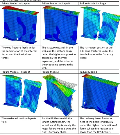
heating. The beam-end tensile force in the catenary tension phase at very high temperature is not affected by the stiffnesses of the beam-end restraints, due to the very low stiffness of the beam itself compared to the connected columns, which stays cool. In all three cases, the beam fails by fracturing the RBS zone. Because the lateral restraints were assigned to the top flanges of all models, the global buckling and local buckling (non-RBS zone) did not occur during the numerical analysis. Hence, only the failure process of the RBS zone is shown as Stage A-D of Failure Mode 1 in Table 4. The failure deflections of the three case are all close to span/20, which are not influenced by the level of end restraints. However, the fire resistance period considerably shortens with higher restraint stiffnesses, since comparing with the low restraint case (1) the beam end bending moment is higher and (2) the difference in capacity between the RBS zone and the connected column is larger.
RBS beams were initially introduced to relieve the beam-end moment for earthquake design and this works as well in fire conditions; comparing with the OB models (Fig. 14), the RBS models survived longer fire resistance periods. This beneficial effect due to the high rotational capacity of RBS is more significant when the end restraint is stiffer, which increases the beam-end bending moment and increase the demand on the moment capacity of the beam. The RBS beam fails at the RBS zone, whereas the OB fails at the beam end (Failure Mode 3 in Table 4). With the same beam-end restraints, the mid-span deflection of the RBS beam is larger than that of OB before failure, due to the RBS’s larger rotational capacity.
In general, the fire resistance period of the model under the low parametric fire is longer under lower end restraints or when the beam has RBS. This effect of RBS on extending the fire resistance period is more signification when the end restraints are higher.
13
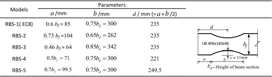
EC8 provides one type of RBS geometrical profile and the FEMA-350 allows a range of cutting dimensions of RBS. Five cutting profiles for UB 406 × 140 × 46 recommended by these two codes are summarised in Table 5. The RBS dimensions are dependent on three parameters: (1) the distance from the edge of the RBS zone to the beam-end,
a
; (2) the cutting length of RBS zone,b
; and (3) thedistance from the centre of the RBS zone (the narrowest section in the beam) to the beam-end,
d
. The effect of the cutting profiles on the fire performance of the RBS beam is presented in this section. Model RBS-1 is the control model (UB 406 × 140 × 46, span 7.2 m, with the axial restraint= 48.6kN/mm and the rotational restraint =13.1 kNm/mrad) adopted in the previous sections. The slow parametric fire is again used in this parametric study and four load ratios (0.3, 0.5, 0.7 and 0.9) are adopted. The ordinary beams with the same end restraints as for the RBS models are also considered for comparison.Figures 15 and 16 show the mid-span deflections and the beam-end axial reaction forces of the models with different cutting geometrical sizes. Under the smallest load ratio (0.3), all RBS models experienced very similar mid-span deflections and the beam-end reaction forces. As the load ratio increases, the differentiation between the models becomes more obvious; in other words, the influence of RBS geometrical profile on the beam’s fire performance is more significant under high load ratios.
14
All RBS models (except RBS-4) survive longer fire resistance period than the ordinary beam (OB model. Since the RBS zone of RBS-4 is the closest to the beam end, it experiences the largest bending moment and shear force and hence the beam has the lowest fire resistance, compared to the other cutting profiles. It can be observed that RBS-4 fractures at the Quasi-Catenary Phase.
The fire resistance of RBS-2 is the second lowest among the five RBS model; it is only larger than that of the RBS-4. This is because RBS-2 has the shortest cutting length and so the lowest rotational ductility, which is needed to relieve the beam-end bending moment to avoid failure.
The performance of RBS-1, RBS-3 and RBS-5 are similar; they all fail by tensile fracture at the RBS zone during the Catenary Phase (Failure Mode 1, Table 4).
In conclusion, controlling the distance d from the RBS zone to the beam end and the cutting length b
during the design of RBS beams is an effective way of achieving satisfactory fire performance. For the beam size analysed, the cutting length b suggested by EC8 and the distance d given by FEMA-350 based on the largest a (= 0.7 bf) will lead the most satisfying fire resistance.
5. Conclusions
This paper presents an investigation on the high-temperature performance of RBS beams, considering the effects of the geometrical size of RBS, beam-end restraints and fire time-temperature relationship. The following conclusions can be made based on the beam models analysed:
15
(2) Under the different fire curves adopted, the fire resistance periods of the RBS models are influenced only by the heating rate. The internal forces and maximum deflections of the beams subject to different fire curves are identical, as they are controlled by the section size and steel temperature;
(3) Controlling the distance from RBS zone to the beam-end and the cutting length during the RBS beam design is an effective method of obtaining sufficient fire resistance. The cutting length proposed by EC8 and the distance from RBS zone to the beam-end suggested by FEMA-350 will lead to the best fire resistance.
It is recognised that further investigations are still needed before the above conclusions could be generalised and applied to all RBS beams subject to all loading conditions in all fire scenarios. For instance, a wider range of RBS beam sections should be analysed and the isolated effects of the axial and rotational restraints should also be investigated.
Acknowledge
The research, in this paper, supported by Jiangsu Key Laboratory of Environmental Impact and Structural Safety in Engineering, China University of Mining & Technology. The authors would like to thank for its support of this area of research as one of the plan items of application and innovation, which is numbered as JSKL2014K02. Last, the authors appreciate the supported by China Scholarship Council (CSC: 201406425001).
Reference
[1] SAC. Interim guidelines: evaluation, repair, modification and design of steel moment frames.Emergency Management Agency,report no. SAC-95-02. 1995.
[2] Roeder C, Foutch D. Experimental Results for Seismic Resistant Steel Moment Frame Connections. J Struct Eng 1996;122:581–8.
16
[4] Chen S, Yeh C, Chu J. Ductile Steel Beam-to-Column Connections for Seismic Resistance. J Struct Eng 1996;122:1292–9.
[5] Pachoumis DT, Galoussis EG, Kalfas CN, Efthimiou IZ. Cyclic performance of steel
moment-resisting connections with reduced beam sections — experimental analysis and finite element model simulation. Eng Struct 2010;32:2683–92.
[6] Sofias CE, Kalfas CN, Pachoumis DT. Experimental and FEM analysis of reduced beam section moment endplate connections under cyclic loading. Eng Struct 2014;59:320–9.
[7] European Committee for Standardization(CEN). Eurocode 3:Design of steel structures,Part 1-8:Design ofjoints. EN1993-1-8,Brussels: 2005.
[8] European Committee for Standardization(CEN). Eurocode 8:Design of structures for earthquake resistance,Part 3:Assessment and retrofitting of buildings. EN 1998-3,Brussels: 2005.
[9] Federal Emergency Management Agency (FEMA). Recommended seismic design criteria for new steel moment frame buildings. FEMA-350, SAC Joint Venture Washington, DC; 2000.
[10] ANSI A. Aisc 358–05 prequalified connections for special and intermediate steel moment frames for seismic applications. Chicago: American Institute of Steel Construction Inc.; 2005.
[11] Newman G, Robinson J, Bailey C. Fire safety design: a new approach to multi-storey steel framed buildings. Ascot Berkshire (UK): SCI Publication; 2000.
[12] Chung H-Y, Lee C-H, Su W-J, Lin R-Z. Application of fire-resistant steel to beam-to-column moment connections at elevated temperatures. J Constr Steel Res 2010;66:289–303.
[13] Selamet S, Garlock ME. Robust fire design of single plate shear connections. Eng Struct 2010;32:2367–78.
[14] Wang M, Wang P. Strategies to increase the robustness of endplate beam–column connections in fire. J Constr Steel Res 2013;80:109–20.
[15] Lee C-H, Chiou Y-J, Chung H-Y, Chen C-J. Numerical modeling of the fire–structure behavior of steel beam-to-column connections. J Constr Steel Res 2011;67:1386–400.
[16] Liu TCH. Effect of connection flexibility on fire resistance of steel beams. J Constr Steel Res 1998;45:99–118.
[17] Pakala P, Kodur V, Selamet S, Garlock M. Fire behavior of shear angle connections in a restrained steel frame. J Constr Steel Res 2012;77:119–30.
[18] The Cardington and Broadgate Fires. http://911research.wtc7.net/mirrors/guardian2/fire/cardi ngton.htm.
17
[20] Dwaikat M, Kodur V. Engineering Approach for Predicting Fire Response of Restrained Steel Beams. J Eng Mech 2010;137:447–61.
[21] NIST. Final Report on the Collapse of World Trade Center Building 7, Federal Building and Fire Safety Investigation of the World Trade Center Disaster. NIST NCSTAR 1A,USA: 2008.
[22] European Committee for Standardization (CEN). Eurocode 3:Design of steel structures,Part 1-2:general rules-structural fire design. EN1993-1-2,Brussels; 2005.
[23] Dai XH, Wang YC, Bailey CG. Numerical modelling of structural fire behaviour of restrained steel beam–column assemblies using typical joint types. Eng Struct 2010;32:2337–51.
[24] Manual AU. Abaqus 6.12. Providence, RI, USA: Dassault Systèmes Simulia Corp.; 2012.
[25] European Committee for Standardization (CEN). Eurocode 3:Design of steel structures,Part 1-1: General rules and rules for buildings. EN1993-1-1,Brussels: 2005.
[26] Yu H, Burgess IW, Davison JB, Plank RJ. Tying capacity of web cleat connections in fire, Part 1: Test and finite element simulation. Eng Struct 2009;31:651–63.
[27] International Standards Organisation. ISO 834-1:Fire-resistance tests-Elements of building construction. General requirements. 1999.
[28] European Committee for Standardization(CEN). Eurocode 1: Actions on structures,Part 1-2: General actions-Actions on structures exposed to fire. EN1991-1-2,Brussels: 2002.
[29] Li G-Q, Guo S-X. Experiment on restrained steel beams subjected to heating and cooling. J Constr Steel Res 2008;64:268–74.
[30] Chinese standard (GB 2003). Code for design of steel structures. In: GB 50017-2003. Beijing. Chinese Plan Press.Beijing,China: 2003.
[31] European Committee for Standardization(CEN). Eurocode 2: Design of concrete structures,Part 1-2: General rules-Structural fire design. EN1993-1-2,Brussels: 2004.
[32] Ohsaki M, Tagawa H, Pan P. Shape optimization of reduced beam section under cyclic loads. J Constr Steel Res 2009;65:1511–9.
<Table>
Table.1 RBS cutting size given by EC8 and FEMA-350 Table.2 Thermal properties of steel
Table.3 The metals damage index of ductile criterion Table.4. Fracture modes of models
Table.5. Geometrical sizes of RBS zone according to the EC8 and FEMA-350
18
Fig.1. RBS joints with circular-cut type (a) geometry of RBS joints; (b) location of plastic hinge in RBS zone; (c) bending moment capacity and design bending moment.
Fig.2.The local buckling and the fracture of beams in Cardington fire test [18]. (a) Cardington office demonstration test (Test 6); (b) Cardington British Steel Test 2: Plane frame test.
Fig.3. Axial force in a restrained steel beam exposed to fire.
Fig.4. Geometrical details of the control model: (a) geometrical size of the RBS beam model with boundary conditions; (b) geometrical size of the RBS zone according to EC8.
Fig.5. ABABUS model of the beam.
Fig.6. Stress-strain curves of structural steel at elevated temperatures
Fig.7. Reduction factors for Young's modulus and yield strength of steel at various temperatures Fig.8. Typical uniaxial stress-strain response of a metal specimen with damage evolution. Fig.9. Four different fire curves used in the numerical modelling.
Fig.10. Results of heat transfer analysis of the RBS models. (a) Parametric Fire-Fast; (b) Parametric Fire-Medium; (c) Parametric Fire-Slow; and (d) Standard Fire.
Fig.11. Test fire curve and temperature distributions in a beam section.
Fig.12 Relationship of mid-span deflection with time of model validation against test data. (a) Mid-span deflections; (b) Axial forces
Fig.13. Mid-span deflections and axial forces of RBS beam models and the ordinary beam model under different fire curves. (a) Mid-span deflections; (b) Axial forces
Fig.14. Performance of RBS models against to OB beam models with different beam-end restraints: (a) Mid-span deflections; (b) Fire-induced axial forces.
Table.1 RBS cutting size given by EC8 and FEMA-350 EC8, Part 3 FEMA350-2000 OMF, SMF
0.6 f
a? b a?(0.5 to 0.7)bf
0.75 d
b? b b?(0.65 to 0.85)bd
0.25 f
c b c 0.25bf
2 2
(4 ) / 8
Table.2 Thermal properties of steel [22]
Value Steel temperature
Specific heat,
c
, (J/kgK)1 3 2 6 3
425-7.73 10· /s/1.69 10· /s -2.22 10· /s C s< 600°C
13002 666
738 s
-/ C s< 735°C
17820 545
731 s
-/ C s< 900°C
650 C s C
Thermal conductivity,
n
, (W/mK)2
54/3.33 10· /s C s< 800°C
27.3 C s C
Table.3 The metals damage index of ductile criterion [26]
Point c Point d Temperature
0.20 0.25 0
400
T C
0.25 0.30 0
500
T? C
0.30 0.50 0
600
T? C
0.57 0.60 0
700
T? C
Table.4. Fracture modes of models
Failure Mode 1 Stage A Failure Mode 1 Stage B Failure Mode 1 Stage
The web fracture firstly under the combination of the internal forces and the fire-induced forces.
The fracture expands in the web and the bottom flange under the higher compression caused by the thermal expansion; and the extreme shear buckling occurs in the web.
The narrowest section at the RBS zone fractures under the tensile forces in the Catenary Phase.
Failure Mode 1 Stage D Failure Mode 2 Failure Mode 3
The weakened section departs fully.
For the RBS beam with the longer cutting length, the lateral instability is usually the major failure mode during the Quasi-Catenary Phase.
The ordinary beam fractures near to the beam-end usually under the higher combination of force, whose fire resistance is
[image:23.595.93.506.93.557.2]Table.5. Geometrical sizes of RBS zone according to the EC8 and FEMA-350
Models Parameters
a
/mmb
/mm d/ mm (=a
+b
/2)RBS-1( EC8) 0.6 bf = 85 0.75bd ?300 235
UB 406x140x46
--Height of beam section d
RBS-2 0.73 bf =104 0.65bd ?262 235
RBS-3 0.46 bf = 64 0.85bd ?342 235
RBS-4 0.5bf ?71 0.75bd ?300 221
RBS-5 0.7bf ?99.5 0.75bd ?300 249.5
Figure 1
Figure 2
Figure 3
Figure 4
Figure 5
Figure 6
Figure 7
Figure 8
Figure 9
Figure 10a
Figure 10b
Figure 10c
Figure 10d
Figure 11
Figure 12
Figure 13a
Figure 13b
Figure 14a
Figure 14b
Figure 15a
Figure 15b
Figure 15c
Figure 15d
Figure 16a
Figure 16b
Figure 16c
Figure 16d
![Table.3 The metals damage index of ductile criterion [26]](https://thumb-us.123doks.com/thumbv2/123dok_us/7842803.176925/22.595.93.251.109.190/table-metals-damage-index-ductile-criterion.webp)




![Enjeux méthodologiques, linguistiques et informatiques pour le traitement du français écrit des sourds (Methodological, linguistic and computational challenges for processing written French of deaf people) [in French]](data:image/gif;base64,R0lGODlhAQABAIAAAP///wAAACH5BAEAAAAALAAAAAABAAEAAAICRAEAOw==)