DEVELOPMENT OF AN EMBEDDED CONTROLLER FOR STEPPER MOTORS APPLICATION
NG POO HENG
“I hereby declared that I have read through this report and found that it has comply
the partial fulfilment for awarding the degree of Bachelor of Electrical Engineering (Power Electronic and Drive)”
Signature : ………
Supervisor’s Name : ………
DEVELOPMENT OF AN EMBEDDED CONTROLLER FOR STEPPER
MOTORS APPLICATION
NG POO HENG
This Report Is Submitted In Partial Fulfilment of Requirement for the Degree of
Bachelor in Electrical Engineering (Power Electronic and Drive)
Fakulti Kejuruteraan Elektrik
Universiti Teknikal Malaysia Melaka
ii
“I hereby declared that this report is a result of my own work except for the excerpts that have been cited clearly in the references.”
Signature : ………
Name : ………
iii
I
ACKNOWLEDGEMENT
In submitting this report, I would like to thanks my supervisor Projek Sarjana
Muda (PSM) - Professor Madya Dr. Zulkifilie bin Ibrahim, for his guidance and
participation in conducting my project. His knowledge and insights were invaluable in
identifying the ways to solve my problems regarding to my project.
I also would like to thanks Puan Maaspaliza binti Azri and Professor Madya Dr.
Ismadi bin Bugis and En.Ahmad Fairuz bin Muhammad Amin as my panels for the
PSM. They shared out their time to attend my presentation PSM. Besides, they also give
their opinions, advice and provide me good idea and knowledge to complete my final
II
ABSTRACT
The project is titled as “Development of an embedded controller for stepper motors application”. In this project, the embedded controller developed is based on Rabbit microprocessor and its core module model RCM 2000. This project is to design
and develop variable speed controlled stepper motor drive using rabbit microprocessor.
The control method implemented in this project is variable speed control method.
Instead of using assembly language to compile the variable speed; this controller will
use Dynamic C programming language to develop the algorithm.
The goal of the project is to design and develop a laboratory scale functioning
prototype in order to demonstrate the interfacing between the variable speed algorithm
in Rabbit microprocessor and the stepper motor speed drive. The Rabbit microprocessor
based variable speed controller is able to generate pulse wave signal. The desired pulse
wave signal generated is an input signal for stepper motor speed drive in order to control
the speed of stepper motor.
The major hardware implementation in this project is Rabbit microprocessor.
Rabbit microprocessor is chosen due to its specification features of high speed,
easy-design hardware system and low power consumption. Besides, variable speed driver also
III
ABSTRAK
Projek ini bertajuk “Pembangunan pengawal padat dan komplek untuk aplikasi
motor stepper dengan menggunakan mikropemproses Rabbit.” Dalam projek ini, satu
pengawal padat yang dibangunkan adalah berteraskan mikropemproses Rabbit dan
modul terasnya RCM 2000. Pengaturcara yang digunakan dalam projek ini adalah
pengawalan perbezaan kelajuan. Satu algoritma kawalan kelajuan perlu dibangunkan
dan dikompil ke dalam mikropemproses Rabbit agar dapat memberikan isyarat kawalan
yang tepat kepada pemacu kelajuan motor stepper. Daripada menggunakan bahasa
himpunan, pengawal yang akan direkacipta ini menggunakan bahasa pengaturcaraan
Dynamic-C yang dikhaskan untuk mikropemproses Rabbit.
Matlamat projek ini adalah untuk merekacipta dan membangunkan satu prototaip
berskala makmal. Prototaip ini diharapkan dapat mendemonstrasikan pengantaraan yang
baik antara algoritma kawalan kelajuan yang dibangunkan dalam mikropemproses
Rabbit, dengan pemacu kelajuan motor stepper. Pengawal laju asas mikropemproses
Rabbit mampu menjanakan isyarat Pulse Wave. Isyarat Pulse Wave yang terjana akan
dijadikan isyarat masukan untuk pemacu dan seterusnya pemacu kelajuan dapat
mengawal kelajuan motor stepper.
Mikropemproses Rabbit dipilih sebagai perkakasan yang utama adalah
disebabkan kelajuan yang tinggi, perekaan perkakasan yang mudah serta peresapan
kuasa yang sedikit yang ditampilkan olehnya. Selain itu, satu pemaju perlu dibangunkan
untuk beroperasi bersama dua atau lebih motor stepper supaya mendapat kelajuan yang
IV
CONTENTS
CHAPTER TOPIC PAGE
ACKNOWLEDGEMENT I
ABSTRACT II
CONTENTS IV
LIST OF FIGURES VII
LIST OF TABLE X
LIST OF LIST OF ABBREVIATIONS XI
LIST OF APPENDICES XII
1 INTRODUCTION 1
1.1 Objectives of the Project 1
1.2 Scope of the Project 1
1.3 Problem Statement 2
2 LITERATURE REVIEW 3
2.1 Embedded Systems 3
2.2 Stepper Motors 5
2.2.1 Unipolar Stepper Motors 8
2.2.2 Bipolar Stepper Motors 10
2.2.3 Advantages of Stepper Motors 11
2.2.4 Applications of Stepper Motors 12
2.3 Pulse Wave 12
2.4 User Interface 13
2.5 Types of Control Method for Stepper Motors Nowadays 14
2.5.1 LF2407 DSP 14
V
System Using the LF2407 DSP
2.5.3 KIM-1 Microcomputer Speed Control of Stepper
Motor 16
3 METHODOLOGY 18
3.0 Project Implementation Flow Chart 18
3.1 Project Planning Grant Chart 19
3.1.1 Project Overall Flow 20
3.1.2 Equipment Used 20
3.1.3 Project Description 23
3.1.3.1 Summary of RCM 2000 Configuration 24
3.2 Hardware Part Process 25
3.2.1 Rabbit Microprocessor Rabbit 2000 25
3.2.1.1 Features and Specifications 26
3.2.1.2 Parallel I/O 29
3.2.1.3 Parallel Port C 30
3.2.1.4 Parallel Port D 31
3.2.1.5 Initializing Parallel Ports by using
Dynamic C 35
3.2.1.6 Memory Mapping 38
3.2.2 Rabbit Core Module, RCM 2000 40
3.2.2.1 Rabbit Core Module 2000 Feature 41
3.2.2.2 RCM 2000 Prototype Board 43
3.2.3 Centent Micro-Step Drive Dive CNO 143 44
3.2.3.1 Specifications 45
3.2.4 Bipolar Stepper Motor Driver L6208N 46
3.2.4.1 Circuit Description 47
3.2.5 Stepper Motors 53
3.2.5.1 Specifications 53
3.2.5.2 Principle of Stepper Motors 54
3.3 Software part process 56
VI
3.4 Procedures to Activate Stepper Motor 57
4 RESULTS 63
4.1 Experimental Setup 63
4.2 Experimental Procedures 65
4.3 Software Development 67
4.4 Interfacing among Hardware and Software 69
4.4.1 Results Analysis 74
4.5 Discussion on the Results 76
5 CONCLUSION 78
5.1 Future Recommendation 78
5.2 Conclusion 78
REFERENCE 80
VII
LIST OF FIGURES
FIGURE TOPIC PAGE
2.1 Embedded circuit 4
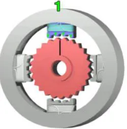
2.2a The top electromagnet (1) is charged, attracting the top most four
teeth of a sprocket 6
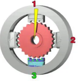
2.2b The top electromagnet (1) is turned off, and the right
electromagnet (2) is charged 7
2.2c The bottom electromagnet (3) is charged; another 3.6° rotation
occurs. 7
2.2d The left electromagnet (4) is enabled 8
2.3 Unipolar stepper motor 8
2.4 Bipolar stepper motor 10
2.5 Waveform of pulse wave 13
2.6 DSP interface 14
2.7 Flowchart of the stepper motor control algorithm 15
2.8 Motor driving circuit 17
3.1 Project Implementation Flow Chart 18
3.2 Block Diagram of Overall Project 20
3.3 Digital multimeter 20
3.4 AC-DC adapter 21
3.5 Oscilloscope 22
3.6 Laboratory DC power supply 23
3.7 Block diagram of the Rabbit microprocessor 28
3.8 Cascaded output registers for Parallel Ports D and E 29
3.9 Parallel Port D block diagram 33
3.10 Parallel port initializing 36
VIII
3.12 Memory addresses accessing in 16-bit logical address space to
20-bit physical address space by MMU. 39
3.13 RCM 2000 connector pin outs 40
3.14 Rabbit Core Module 2000 41
3.15 RCM 2000 subsystem 42
3.16 Rabbit Core Module 2000 prototype board 43
3.17 Centent micro-step drive CNO 143 45
3.18 Typical application L6208N IC type bipolar stepper motor driver 46
3.19 Diagram half drive mode 47
3.20 Diagram normal drive mode 48
3.21 Diagram wave drive mode 49
3.22 Charge pump Circuit 50
3.23 Fast decay mode output stage configurations 51
3.24 Slow decay mode output stage configurations 51
3.25 Diagram of pins connection L6208N driver 52
3.26 Diagram switching characteristic 52
3.27 Sanyo Denki bipolar stepper motor 53
3.28a Internal structure of stepper motor 54
3.28b Rotation clock-wise of stepper motor 55
3.28c Rotation counter clock-wise of stepper motor 55
3.29 Activate stepper motor via function generator and Centent CNO
143 driver 57
3.30 Activate stepper motor via RCM 2000 controller and L6208N
driver 58
3.31 Block diagram of stepper motors via RCM 2000 controller 59
3.32 Stepper motors control flow chart 61
3.33 State diagram of the stepper motors speed performances 62
4.1 Connect Programming Cable to RCM 2000. 64
4.2 Software Dynamic C opens the new project 67
4.3 Software Dynamic C selects the project option. 68
4.4 Project option in communication and targetless. 68
4.5 Desire pulse wave programming 69
IX
4.7 Diagram of connection L6208N driver circuit 70
4.8 Control panel circuit 71
4.9 Integration between Rabbit Core Module (RCM 2000) with speed
control panel box 71
4.10 Diagram of integration between RCM 2000 parallel ports with
control panel circuit 72
4.11 Integration of the stepper motor, driver, prototype board and
Rabbit Core Module (RCM 2000) 73
4.12 Diagram of integration stepper motors, drivers, prototype board
and Rabbit Core Module (RCM 2000) 73
4.13 500Hz pulse wave 74
4.14 Approximately 600Hz pulse wave 74
4.15 Approximately 1000Hz pulse wave 75
X
LIST OF TABLES
TABLE TOPIC PAGE
3.1 Project planning Grant chart 19
3.2 Summary of RCM 2000 Configuration 24
3.3 Summary of port inputs and port outputs 25
3.4 Parallel Port C register 30
3.5 Parallel Port C data register and functions register 31
3.6 Parallel Port D registers 32
3.7 Parallel Port D data registers 34
3.8 Parallel Port D Control Register 34
3.9 Description pins for the Centent micro-step drive CNO 143 46
3.10 Electrical characteristic of L6208N driver 52
3.11 Specification 103Z710-1 Sanyo Denki bipolar stepper motor 53
3.12a Clock-wise rotating table 55
3.12b Counter clock-wise rotating table 55
XI
LIST OF ABBREVIATIONS
AC - Alternating Current
RCM - Rabbit Core Module
PC - Personal Computer
I/O - Input/ Output
RAM - Random Access Memory
XII
LIST OF APPENDICES
NO TITLE PAGE
1 Datasheet of L6208N Bipolar Stepper Motors Driver 83
2 Programming Source Code of Variable Speed Control Stepper Motors
1
CHAPTER 1
INTRODUCTION
1.1 Objectives
To generated desire pulse wave signal as an input signal for stepper motor speed drive in order to control the speed of stepper motors by using
Rabbit Microprocessor.
To develop a user interface (push buttons, on-off switches) programming
to interface with multi-stepper motors.
1.2 Scope
Develop a speed control algorithm to drive the stepper motors.
Develop the desire pulse waves by using Dynamic C programming.
Develop an IC type stepper motor driver.
Develop a programming to interface with multi-stepper motors.
Develop a user interface (push buttons, on-off switches) variable speed
2
1.3 Problem Statement
Nowadays, the conventional controller of stepper motors speed mostly based on
Digital Signal Processor (DSP), Programmable Logic Controller (PLC) or PC-based
controller. Furthermore, these controllers might be costly and difficult to be
re-programmed. Hereby, on the terms of cost effective and easy to program, a controller
with minimize number of components need to de developed by using 8 bits Rabbit
microprocessor.
The main objective is to design and develop variable speed stepper motor by
using rabbit microprocessor. The desired pulse waves are creating to generate the
variable speed stepper motor by using Rabbit Core Module (RCM 2000) prototyping
board. Examples for the application of stepper motors are X-Y plotters, electric
typewriters, and control of disk drives, robots, and numerical control of machine tools.
The variable speed drive will be designed to interface with the stepper motor.
Hence, by using Dynamic C language known as high level programming language will
be develop to compile into the memory system of Rabbit Microprocessor. Then, the
rabbit microprocessor of RCM 2000 will be integrating with the stepper motors in order
3
CHAPTER 2
LITERATURE REVIEW
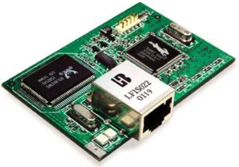
2.1 Embedded Systems
Basicallyanembedded system consists of:
Microcontroller, digital signal processor (DSP)
Random access memory (RAM), disk on chip
Flash memory
Power consumption 3V-12V
Microprocessor based 32 bits- 64 bits
Peripheral input and output (I/O)
Operating system (OS)
i. Disk operating system (DOS)
ii. Window CE
4
An embedded system is a special-purpose computer system designed to perform
one or a few dedicated functions. It is usually embedded as part of a complete device
including hardware and mechanical parts. In contrast, a general-purpose computer, such
as a personal computer, can do many different tasks depending on programming. Since
the embedded system is dedicated to specific tasks, design engineers can optimize it,
reducing the size and cost of the product, or increasing the reliability and performance.
Some embedded systems are mass-produced, benefiting from economies of scale. [1]
Physically, an embedded systems range from portable devices such as digital
watches and MP3 players, to large stationary installations like traffic lights, factory
controllers, or the systems controlling nuclear power plants. Complexity varies from low,
with a single microcontroller chip, to very high with multiple units, peripherals and
networks mounted inside a large chassis or enclosure.
In general, "embedded system" is not an exactly defined term, as many systems
have some element of programmability. For example, Handheld computers share some
elements with embedded systems - such as the operating systems and microprocessors
which power them - but are not truly embedded systems, because they allow different
[image:21.612.212.449.498.664.2]applications to be loaded and peripherals to be connected.
5
2.2 Stepper Motors
Stepper motor is a permanent magnet or variable reluctance dc motor that has the
following performance characteristics:
1. Rotation in both directions,
2. Precision angular incremental changes,
3. Repetition of accurate motion or velocity profiles,
4. A holding torque at zero speed, and
5. Capability for digital control.
Commonly the stepper motors can be divided in two types: Unipolar stepper motors
Bipolar stepper motors
A stepper motor is an electric machine that rotates in discrete angular increments
or steps. Stepper motors are operated by applying current pulses of a specific frequency
to the inputs of the motor. Each pulse applied to the motor causes its shaft to move a
certain angle of rotation, called a stepping angle. [2]
The stepper motor also possesses drawbacks such as the possibility of losing
synchronism, harmonic resonance, and small oscillations at the end of each step. With
the above parameters in mind, the stepper motor is used in applications such as printers,
plotters, X-Y tables, facsimile machines, barcode scanners, image scanners, copiers,
medical apparatus, and other devices. The stepper motor has salient poles on both the
stator and the rotor, and normally only the stator poles hold the poly-phase windings
called the control windings. Usually stepper motors are classified as
Active rotor (permanent magnet rotor) Reactive rotor (reluctance type)
6
While each of these types of stepper motors has merit, hybrid stepper motors are
becoming more popular in industrial applications. In this chapter, we focus on the
principles and implementation of a hybrid stepper motor control system using the
LF2407 DSP controller.
A stepper motor can move in accurate angular increments know as steps in
response to the application of digital pulses to an electric drive circuit from a digital
controller. The number and rate of the pulses control the position and speed of the motor
shaft. Generally, stepper motors are manufactured with steps per revolution of 12, 24, 72,
144, 180, and 200, resulting in shaft increments of 30, 15, 5, 2.5, 2, and 1.8 degrees per
step.
Stepper motors are either bipolar, requiring two power sources or a switchable
polarity power source, or unipolar, requiring only one power source. They are powered
by dc current sources and require digital circuitry to produce the coil energizing
sequences for rotation of the motor. Feedback is not always required for control, but the
use of an encoder or other position sensor can ensure accuracy when it is essential. The
advantage of operating without feedback is that a closed loop control system is not
required. Generally, stepper motors produce less than 1 horsepower (746W) and are
[image:23.612.286.411.509.636.2]therefore frequently used in low-power position control applications.
Figure 2.2a: The top electromagnet (1) is charged, attracting the top most four
7
Figure 2.2b: The top electromagnet (1) is turned off, and the right electromagnet
(2) is charged, pulling the nearest four teeth to the right. This
results in a rotation of 3.6 °.
Figure 2.2c: The bottom electromagnet (3) is charged; another 3.6° rotation
[image:24.612.286.415.326.460.2]