Int. J. Electrochem. Sci., 8 (2013) 5407 - 5420
International Journal of
ELECTROCHEMICAL
SCIENCE
www.electrochemsci.org
Solution Plasma Sputtering Processes for the Synthesis of
PtAu/C Catalysts for Li-Air Batteries
Chiaki Terashima1,†,*, Yujiro Iwai1, Sung-Pyo Cho1, Tomonaga Ueno1,2, Nobuyuki Zettsu1,2, Nagahiro Saito1,2,3,4, Osamu Takai1,3,4
1
Department of Materials, Physics and Energy Engineering, Graduate School of Engineering, Nagoya University, Furo-cho, Chikusa-ku, Nagoya 464-8603, Japan
2
Green Mobility Collaborative Research Center, Nagoya University
3
Eco-Topia Science Institute, Nagoya University
4
CREST, Japan Science and Technology Agency (JST), Tokyo 102-0075, Japan
†
Present Address: Division of Energy and Environment Photocatalyst, Research Institute for Science & Technology, Tokyo University of Science, 1-3 Kagurazaka, Shinjuku-ku, Tokyo 162-8601, Japan
*
E-mail: [email protected]
Received: 21 February 2013 / Accepted: 12 March 2013 / Published: 1 April 2013
Clean, nanosized PtAu/C catalysts were fabricated, using a simple one-step synthesis technique that involved sputtering discharge in liquid, and did not require the use of chemical species such as surfactants and/or reductants. This solution plasma sputtering was driven by a pulsed power supply, and was performed on the discharge between Pt and Au targets in a liquid dispersion of carbon black. Fine PtAu nanoparticles with an average diameter of 5.7 nm were uniformly deposited on the carbon support. The production and composition of the PtAu nanoparticles could be controlled via changes in the sputtering conditions. The Au-rich Pt19Au81/C (atomic %) catalysts provided higher specific
capacity, even in carbonate-based electrolyte Li-air batteries, reducing the amount of Li2CO3 that was
deposited on the bare carbon.
Keywords: electrochemistry; Li-air battery; nanoparticles; plasma chemistry; sputtering
1. INTRODUCTION
discharge products such as lithium oxides and lithium carbonate at the air electrode [3]. Carbon supports with high surface area or high porosity are effective in reducing the clogging rate, and Ketjen Black among carbon blacks [4], graphene nanosheets [5], mesocellular carbon foam [6], and carbon nanotube/carbon nanofibers [7] were reported to show a high discharge capacity. Alternative attempts to avoid these deposits by preventing their formation (rather than through the design of the structure of the carbon support) have also been made, using either metal oxide or metal nanoparticles (NPs) as electrocatalysts; these were beneficial in obtaining higher specific capacities [813]. Bifunctional PtAu/C electrocatalysts have had further impact in both the scientific and industrial fields because of— in addition to their enhanced capacity—their remarkable electrocatalytic activity toward reducing the overpotential for discharge and charge [12]. These results indicated that the discharge and charge reactions occurred on the Au and Pt surfaces, respectively.
PtAu/C has been fabricated using the chemical reduction method, which has the disadvantages of requiring chemical species such as reducing and/or stabilizing agents, severe thermal treatment, and time-consuming, multistep processes. It is known that if the catalyst surface is capped or adsorbed with surfactants or impurities, it will exhibit significantly reduced catalytic activity [14], and the thermal treatment to remove these chemicals leads to the aggregation of NPs [15]. With the aim of obtaining clean NPs, pulse electrodeposition technology was used to make the PtAu catalysts [16], however, their particle sizes were within the range of 200 nm to 300 nm and were somewhat large. As alternative technique, low-pressure metal-vapor-deposition and metal-sputter-deposition methods have been developed [1719]; however, the recovery of NPs from the vacuum chamber is a complicated process, because the NP synthesis occurs in the gas phase and under low pressure. Furthermore, to the best of our knowledge, no reports exist showing that vacuum synthesis techniques have been used to successfully deposit NPs over the entire surface of nano/microsized support materials.
2. EXPERIMENTAL
2.1 Synthesis of PtAu/C by SPS
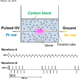
Figure 1. Schematic diagram of the experimental setup for the synthesis of PtAu/C by SPS process, and the typical waveforms applied by the pulsed power supply. The voltage waveforms were depicted in waveform A and B, showing the mean voltage 900 V and 2500 V, respectively. Both waveforms were based on the pulse frequency of 20 kHz and the pulse width of 2 s. Waveform A was continuous, while waveform B had off-and-on pattern.
[image:3.596.131.470.102.445.2]
on the waveform A. On the other hand, the waveform B was cycled with off-and-on pattern, i.e., the half of 500 s showed the no-applied field, in order to impart high energy per pulse on the electrodes. The current and the voltage waveforms were measured using a current probe (Current Probe PR 30) and a voltage probe (Tektronix P6015 A), respectively, connected to an oscilloscope (Tektronix TDS 2002). After an appropriate discharge time, the suspension was filtered and washed with distilled water 3-4 times, and then vacuum-dried.
2.2 Linear sweep voltammetry
To evaluate the electrochemical properties of the catalysts, linear sweep voltammetry (LSV) was performed in three-electrode system. Electrochemical measurements were made with a potentiostat/galvanostat (CH Instruments, model 600A). The working electrode was prepared as follows: a 25 l aliquot of the mixture containing 20 mg of carbon black or PtAu/C in 2.5 ml ethanol was cast on the mirror-polished glassy carbon substrate (1 cm2) and dried in air, and followed by Nafion solution casting and drying. A 12.5 l of 0.16 wt% Nafion solution diluted in 60 wt% ethanol-water was pipetted onto the dried catalyst layer, and heat-treated at 130 C for 30 min in air to immobilize on the substrate by Nafion. A commercial Ag/Ag (0.01 M AgNO3, 0.1 M tetrabutyl
ammonium perchlorate dissolved with acetonitrile) reference electrode (+3.53 0.02 V versus Li/Li+) was employed in nonaqueous solution. The electrolyte was 1 M LiClO4 in a propylene carbonate
(PC):ethylene carbonate (EC) (1:1 by weight ratio). After bubbling oxygen or argon for 30 min, linear sweep voltammograms for the oxygen reduction reaction in Li-ion containing aprotic electrolyte were recorded by sweeping the potential from 4.0 V to 2.5 V vs. Li/Li+ at 20 mV/s.
2.3 Fabrication of Li-air batteries and their electrochemical measurements
The air electrode was fabricated by compressing a mixture of 20 mg of carbon black or PtAu/C and polyvinylidene difluoride as a binder in a weight ratio of 85:15 at 8 MPa. The area of circular electrode was 1 cm2. A lithium foil (thickness: 1 mm) was purchased from Honjo Chemical Corp. and used as received. These cathode and anode electrodes were pressed onto the current collector of copper mesh (Mitsubishi Materials), and were separated by a polypropylene electrolytic membrane dipping with 1 M LiClO4 in PC/EC (1:1). A top surface of air electrode was covered by Neoflon FEP film
(Daikin Industries Ltd.) to avoid the problems associated with humidity and carbon dioxide in air. These assemblies were constructed in an argon atmosphere globe box. Battery tests were conducted with a Solartron SI 1280 B at current density of 0.1 mA/cm2 for discharge and 0.5 mA/cm2 for charge. The cutoff voltage in discharge was set to 2.0 V.
2.4 Characterization of PtAu/C catalyst
2500SE (JEOL) operated at 200 kV. The lattice resolution was 0.14 nm. The crystal structure of the samples was carried out by X-ray diffraction (XRD) using a Rigaku Smart Lab with a Cu target radiated at 45 kV and 200 mA. Inductively coupled plasma atomic emission spectroscopy (ICP-AES) (Perkin Elmer, Optima 3300DV) was used to determine qualitatively and quantitatively the elements in the samples.
3. RESULTS AND DISCUSSION
3.1 Synthesis and characterization of PtAu/C created using SPS
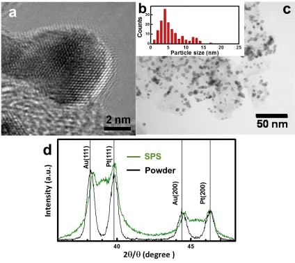
Figure 2. PtAu/C synthesis produced using SPS: (a) HRTEM image; (b) particle size distribution obtained from (c) image; (c) BF-STEM image; (d) XRD patterns of NPs on carbon black through the SPS process, and a mixture of Pt and Au powders.
[image:5.596.83.507.260.639.2][image:6.596.181.414.163.404.2]
energy-dispersive X-ray spectroscopy (EDS), and XRD, to clarify the characteristics of the PtAu/C. Figure 2 shows the high-resolution TEM (HRTEM) and BF-STEM results, and the distribution of the particles. The average diameter was 5.7 nm, with a relative standard deviation of 3.6 nm, and the EDS analysis showed that all of the NPs were composed of Pt and Au.
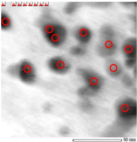
[image:6.596.157.440.502.718.2]Figure 3. EDS point analysis of PtAu NPs on the carbon support produced by the SPS conditions such as waveform B and the interelecrtrode gap of 0.6 mm. The result is shown in Table 1.
Table 1. The result of EDS point analysis (Figure 3).
Number Pt (atomic %) Au (atomic %)
1 37.5 62.5
2 55.0 45.0
3 60.1 39.9
4 82.6 17.4
5 24.4 75.6
6 16.8 83.2
7 0.0 100.0
8 35.8 64.2
9 72.8 27.2
10 46.9 53.1
11 100.0 0.0
The histogram revealed that the produced NPs were well dispersed, but some aggregates over 10 nm in size were observed. Under the present experimental conditions, the solution temperature reached approximately 70C after 30 min of discharge. Based on our recent success in the production of well-dispersed, sub-2-nm Au clusters using SPS in liquid nitrogen [36], it is highly likely that the low-temperature surroundings played a role in condensing the expanded plasma particles. Figure 2d shows XRD data for the NPs obtained on carbon black, compared with a mixture of Pt and Au powders. The peaks for Au(111) and Au(200) shifted to higher angles, and new, broad peaks appeared at 39.1 and 45.3, respectively. The peak for the Au powder(111) at 38.1 matched with the standard JCPDS data, while that for the NPs shifted to 38.4. The face-centered cubic (fcc) structure of Au may have substituted for the Pt atoms, which also had an fcc crystal structure. The lattice parameter of Pt is 0.392 nm, which is smaller than that of Au (0.408 nm); the partial replacement of Au with Pt would therefore result in the observed peak shift. The broad peak further confirmed the presence of the Pt-Au bimetals, as well as the heterogeneous distribution of the Pt and/or Au NPs [13]. We observed a varied distribution of NPs, with both alloyed and segregated Pt and Au phases, as determined from the EDS point analysis (Figure 3 and Table 1). The average atomic ratio of PtAu was calculated to be Pt48Au52 ,
and the metal loading was 31 wt%.
3.2 Control of the composition of PtAu NPs via changes in the SPS conditions
[image:7.596.117.477.415.704.2]
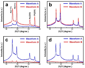
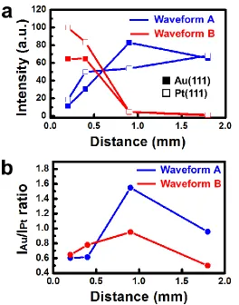
Figure 5. Effects of the amount and the composition for PtAu NPs on the SPS conditions such as pulsed waveform and interelectrode gap: (a) peak intensities for Au(111) and Pt(111) obtained from XRD patterns (Figure 4); (b) Intensity ratio of Au/Pt estimated by the data (a).
[image:8.596.165.429.92.428.2]
selective sputtering of Au, with a binding energy of 3.97 eV—lower than that of Pt (7.58 eV) [3739]—would have led to an increase in the amount of sputtering, via the breakage of bonds by heat-induced thermal vibration. In fact, the solution temperature with an electrode gap of 1.8 mm was approximately 20C higher than the value of ca. 60C measured with a 0.2-mm gap. The decrease in the amount of sputtering for distances larger than 1.8 mm may have been a result of the reduced electric field in the plasma in the interelectrode space. The applied voltage was actually independent of the electrode distance in the range from 0.2 mm to 1.8 mm. On one hand, waveform B, with its high energy per pulse, produced both Au and Pt NPs, mainly at small electrode separations. When the distance increased, however, the NPs were not entirely produced. The comparatively long interval of waveform B might have led to the difficulties in the generation of the plasma. From the monitoring of the current and voltage profiles, the current was almost zero at long distances (for example, with a 1.8-mm gap). Judging from visual observations, the discharge was actually discontinuous.
3.3 Effect of the composition of PtAu NPs on the oxygen reduction reaction in Li-ion containing aprotic electrolyte
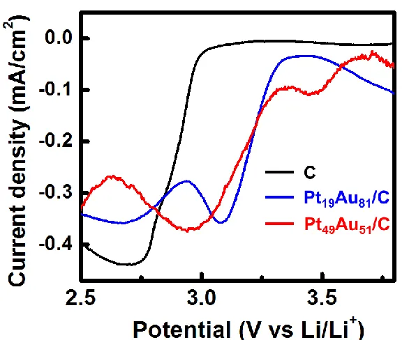
Figure 6. LSVs for un-modified carbon, Pt19Au81/C and Pt49Au51/C electrodes in O2-saturated 1 M
LiCiO4/PC-EC at 20 mV/s.
[image:9.596.146.444.359.603.2]
be Pt19Au81 using ICP-AES, and that of the latter was found to be Pt49Au51, which was in very good
agreement with the results from the EDS point analysis. Figure 6 shows background-subtracted linear sweep voltammograms for oxygen reduction in 1 M LiClO4/PC-EC, at un-modified carbon,
Pt19Au81/C, and Pt49Au51/C electrodes. Both modified electrodes showed a positive shift in the
reduction signals, indicating their high electrocatalytic activity. At the Pt49Au51/C electrode, two
reduction peaks were observed at 3.45 V and 2.95 V vs. Li/Li. From the results for Pt49Au51/C, as well
as the bulk metallic Au and Pt (data not shown), the higher peak at 3.45 V was assigned to the reaction on the Pt surface. The lower peak at 2.95 V on Pt49Au51/C, and the reduction peak at 3.08 V on Au rich
Pt19Au81/C corresponded with oxygen reduction on the Au surface. This electrocatalytic trend for the
oxygen reduction activity, Pt Au C, was similar to the result for oxygen reduction to water in an aqueous media. It has been known for the past four decades that Pt and Au with atomic height steps, kinks in the steps, and a high Miller Index are catalytic, and effective in breaking chemical bonds [40,41]. Therefore, the addition of Pt, Au or PtAu NPs to carbon materials can result in a lower overpotential for oxygen reduction in Li-ion-containing aprotic electrolytes; as a result, the discharge voltage of Li-air batteries with these catalysts may be higher. Interestingly, however, the reductive signal related to the reaction on the Pt surface was observed only on the first negative sweep. That is, the peak at 3.45 V observed on Pt49Au51/C disappeared after a second sweep. This poorly-reproducible
signal may have resulted in strong solvent adsorption on the Pt, driven by the strong chemical interactions. The effect of the Pt catalyst on the oxygen reduction was therefore restrictive. The lower catalytic activity of Pt, which was also reported by Lu et al. [10], resulted in an activity trend of Pt19Au81/C Pt49Au51/C C. Here, the electrochemical activity was compared by the reduction
potential at the maximum reduction current from the result in Figure 6.
3.4 Evaluation of PtAu/C catalyst in Li-air batteries
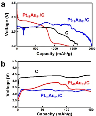
The electrochemical performances (such as the cell voltage and capacity) of the cell with and without catalysts were assessed under a discharge current density of 0.1 mA/cm2. Figure 7a shows the discharge curves for Li-air batteries, in which the air electrodes were made from un-modified carbon, Pt19Au81/C, and Pt49Au51/C prepared at section 3.3. The discharge capacity at Pt19Au81/C was much
higher than that of carbon black, although the curves were fractured and noisy; this was because the experiments were conducted at room temperature and using air, not pure oxygen gas. This high capacity of Pt19Au81/C enhanced the performance of the PtAu catalyst; in contrast, however, that of
Pt49Au51/C became lower, even in comparison with bare carbon. Furthermore, although the cell voltage
of Pt49Au51/C was high—over 3 V in the initial stage—a steep fall in the battery voltage and a
Figure 7. Performance of Li-air batteries using a carbonate-based electrolyte: (a) discharge curves for un-modified carbon, Pt19Au81/C and Pt49Au51/C cathodes under a constant current density of
0.1 mA/cm2; (b) charge curves at 0.5 mA/cm2.
The reaction on the cathode remains unclear, although much effort has been dedicated to understanding it. It was traditionally considered that the electrochemical reaction in an Li-air battery was 2Li 2e O2 Li2O2 in an aprotic electrolyte [9], but the reaction mechanism was likely to
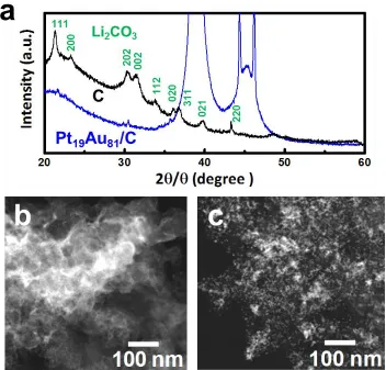
depend on the catalyst and the electrolyte solvent. It is therefore desirable to investigate the byproducts after discharge. Figure 8a shows XRD patterns for carbon black and Pt19Au81/C after the first discharge
to 2 V. The formation of Li2CO3 was clearly observed in the case of the carbon-based air electrode.
This result agreed well with a previous report for pure carbon [42]. The decomposition of alkyl carbonates after cell discharge likely leads to the electrodeposition of Li2CO3 on the carbon cathode.
However, only a small amount of Li2CO3 was detected on the Pt19Au81/C catalyst at the end of the
discharging process. This result was supported by the DF-STEM results shown in Figure 8b and c. The highly dense, bright areas were mostly observed on the pure carbon, showing the formation of more Li2CO3; on the Pt19Au81/C, in contrast, we could see finely distributed deposits, which matched with
[image:11.596.149.457.99.472.2]
Figure 8. Analysis of the byproducts on the cathodes after discharge: (a) XRD patterns for un-modified carbon and Pt19Au81/C cathodes; (b) STEM image of un-modified carbon; (c)
DF-STEM image of Pt19Au81/C.
Even when a carbonate-based electrolyte was used, small amounts of Pt catalyst were effective in inhibiting the formation of electrodeposits. In addition to this catalytic effect, the Pt19Au81/C catalyst
demonstrated the highest charging activity, compared with pure carbon and the Pt49Au51/C catalyst
(Figure 7b). Lu et al. performed pioneering and systematic work on the effects of catalysts such as Pt, Au, and PtAu [1013,43]; here, we revealed catalytic activity on the PtAu surface for the first time, even in carbonate-based electrolytes, using clean Pt19Au81/C produced using the SPS method. The less
Pt composition of the catalyst, Pt19Au81/C, allowed a higher capacity and a remarkable activity for
reducing the charge voltage.
4. CONCLUSIONS
[image:12.596.124.476.93.430.2]
properties were likely the consequence of not only the relatively small nanosized particles, but also their clean surfaces. This unique process could also be used to control the composition of the PtAu NPs, by changing the pulsed waveform and the interelectrode gap. Two types of PtAu NPs supported on carbon materials (Pt19Au81/C and Pt49Au51/C) were investigated as an air electrode in an Li-air
battery, using a carbonate-based electrolyte, and were compared with bare carbon black. The battery with less Pt of Pt19Au81/C catalyst could enhance the discharge capacity to give values as high as 1980
mAh/g at a current density of 0.1 mA/cm2. The specific capacity of 1600 mAh/g at bare carbon was due to the large amount of deposited Li2CO3, as determined using XRD analysis. Interestingly, a lower
discharge capacity was obtained with the Pt49Au51/C catalyst; the electrocatalytic activity might have
been hampered by the strong solvent adsorption on the Pt surface. This novel sputtering technology-based process could be extended for the one-step synthesis of tailored nanomaterials with a combination of constituent elements.
ACKNOWLEDGEMENT
This work was partially supported by Core Research for Evolutional Science and Technology (CREST) of Japan Science and Technology Agency (JST) and Knowledge Cluster Initiative, “Tokai Region Nanotechnology Manufacturing Cluster”, sponsored by Ministry of Education, Culture, Sports, Science and Technology (MEXT). We are indebted to S. Akiyama for ICP-AES measurement.
References
1. K. M. Abraham and Z. Jiang, J. Electrochem. Soc., 143 (1996) 1.
2. G. Girishkumar, B. McCloskey, A. C. Luntz, S. Swanson and W. Wilcke, J. Phys. Chem. Lett., 1 (2010) 2193, and refs. cited in.
3. J. Christensen, P. Albertus, R. S. Sanchez-Carrera, T. Lohmann, B. Kozinsky, R. Liedtke, J. Ahmed and A. Kojic, J. Electrochem. Soc., 159 (2012) R1.
4. E. Yoo and H. Zhou, ACS Nano, 5 (2011) 3020.
5. H. Minowa, M. Hayashi, M. Takahashi and T. Shodai, Electrochemistry, 78 (2010) 353. 6. G. Q. Zhang, J. P. Zheng, R. Liang, C. Zhang, B. Wang, M. Hendrickson and E. J. Plichta, J.
Electrochem. Soc., 157 (2010) A953.
7. X.-H. Yang, P. He, and Y.-Y. Xia, Electrochem. Commun., 11 (2009) 1127.
8. A. Débart, J. Bao, G. Armstrong and P. G. Bruce, J. Power Sources, 174 (2007) 1177.
9. T. Ogasawara, A. Débart, M. Holzapfel, P. Novák and P. G. Bruce, J. Am. Chem. Soc., 128 (2006) 1390.
10.Y.-C. Lu, H. A. Gasteiger, E. Crumlin, R. McGuire and Y. Shao-Horn, J. Electrochem. Soc., 157 (2010) A1016.
11.Y.-C. Lu, H. A. Gasteiger and Y. Shao-Horn, J. Am. Chem. Soc., 133 (2011) 19048.
12.Y.-C. Lu, H. A. Gasteiger, M. C. Parent, V. Chiloyan and Y. Shao-Horn, Electrochem. Solid-State Lett., 13 (2010) A69.
13.Y.-C. Lu, Z. Xu, H. A. Gasteiger, S. Chen, K. Hamad-Schifferli and Y. Shao-Horn, J. Am. Chem. Soc., 132 (2010) 12170.
14.C. A. Stowell, and B. A. Korgel, Nano Lett., 5 (2005) 1203.
17.Y. Shishino, T. Yonezawa, S. Udagawa, K. Hase and H. Nishihara, Angew. Chem. Int. Ed., 50 (2011) 703.
18.N. S. Tabrizi, Q. Xu, N. M. van der Pers, U. Lafont and A. Schmidt-Ott, J. Nanopart. Res., 11 (2009) 1209.
19.T. Torimoto, K. Okazaki, T. Kiyama,; K. Hirahara, N. Tanaka and S. Kuwabata, Appl. Phys. Lett., 89 (2006) 243117.
20.K. Baba, T. Kaneko and R. Hatakeyama, Appl. Phys. Express, 2 (2009) 035006. 21.C. Richmonds and M. P. Sankaran, Appl. Phys. Lett., 93 (2008) 131501.
22.X. Liang, Z.-J. Wang and C.-J. Liu, Nanoscale Res. Lett., 5 (2010) 124. 23.O. Takai, Pure Appl. Chem., 80 (2008) 2003.
24.J. Hieda, N. Saito and O. Takai, J. Vac. Sci. Technol. A, 26 (2008) 854.
25.Y. Ichin, K. Mitamura, N. Saito and O. Takai, J. Vac. Sci. Technol. A, 27 (2009) 826. 26.N. Saito, J. Hieda and O. Takai, Thin Solid Films, 518 (2009) 912.
27.P. Pootawang, N. Saito and O. Takai, Mater. Lett., 65 (2011) 1037. 28.P. Pootawang, N. Saito and O. Takai, Thin Solid Films, 519 (2011) 7030. 29.M. A. Bratescu, N. Saito and O. Takai, Curr. Appl. Phys., 11 (2011) S30.
30.M. A. Bratescu, S.-P. Cho, O. Takai and N. Saito, J. Phys. Chem. C, 115 (2011) 24569. 31.S.-P. Cho, M. A. Bratescu, N. Saito and O. Takai, Nanotechnology, 22 (2011) 455701. 32.P. Baroch, V. Anita, N. Saito and O. Takai, J. Electrostatics, 66 (2008) 294.
33.P. Pootawang, N. Saito and O. Takai, Jpn. J. Appl. Phys., 49 (2010) 126202.
34.M. A. Bratescu, J. Hieda, T. Umemura, N. Saito and O. Takai, J. Vac. Sci. Technol. A, 29 (2011) 031302.
35.I. Prasertsung, S. Damrongsakkul, C. Terashima, N. Saito and O. Takai, Carbohydrate Polymers, 87 (2012) 2745.
36.X. Hu, S.-P. Cho, O. Takai and N. Saito, Cryst. Growth Des., 12 (2012) 119. 37.M. Mayer, G. Pacchioni and N. Rösch, Surf. Sci., 412/413 (1998) 616.
38.H. Cotal, C. Fetzer, J. Boisvert, G. Kinsey, R. King, P. Hebert, H. Yoon and N. Karam, Energy Environ. Sci., 2 (2009) 174.
39.E. Mete, O. Gülseren and Ş. Ellialtıoğlu, Eur. Phys. J. B, 85 (2012) 204. 40.G. A. Somorjai and D. W. Blakely, Nature, 258 (1975) 580.
41.N. Tian, Z.-Y. Zhou, S.-G. Sun, Y. Ding and Z. L. Wang, Science, 316 (2007) 732.
42.J. Xiao, J. Hu, D. Wang, D. Hu, W. Xu, G. Graff, X. Nie, J. Liu and J.-G. Zhang, J. Power Sources, 196 (2011) 5674.