Channel Prediction Aided Coded Modulation Assisted
Eigen-Beamforming
S. X. Ng, W. Liu, L.-L. Yang and L. Hanzo
School of ECS, University of Southampton, SO17 1BJ, United Kingdom. Tel: +44-23-8059 3125, Fax: +44-23-8059 4508
Email:{sxn,wl03r,lly,lh}@ecs.soton.ac.uk, http://www-mobile.ecs.soton.ac.uk
Abstract— Eigen-beamforming is capable of providing attractive per-formance gains in the context of Multiple-Input Multiple-Output (MIMO) systems, provided that accurate Channel State Information (CSI) is available. However, when a realistic pilot-based channel predictor is used for acquiring the CSI, a significant performance degradation may be imposed by the phase-ambiguity inherent in the estimated eigen-vectors. In this contribution, both sophisticated Coded Modulation (CM) schemes and differentially encoded CM schemes are employed for assisting the operation of the eigen-beamformer, when employing a minimum mean square error based pilot-assisted channel predictor. It is shown that differentially encoded CM schemes are capable of assisting the eigen-beamformer in attaining a coding gain of about 6.5 dBs, when communicating over correlated Rayleigh fading channels.
I. INTRODUCTION
Wireless systems employing multiple transmitters and receivers are capable of providing high data rates by exploiting the high capacity potential of Multiple-Input Multiple-Output (MIMO) channels [1], [2]. Within the broad family of MIMO systems, Space-Time Coding schemes [3], [4] are capable of attaining attractive spatial diversity gains without requiring any Channel State Information (CSI) at the transmitter. By contrast, transmit beamforming [5], [6] requires accurate CSI at the transmitter for guaranteeing low-SNR operation. For the sake of efficiently exploiting the available radio spectrum, joint coding and modulation termed as Coded Modulation (CM) was proposed by Ungerb¨ock in 1982 [7] for non-dispersive Gaussian channels. The benefit of TCM is that it is capable of achieving a coding gain in comparison to uncoded transmissions by expanding the modulation phasor constellation, hence absorbing the parity bits without bandwidth expansion. Ungerb¨ock’s contribution motivated intensive research on TCM, especially after the conception of turbo codes by Berrou et al. [8], leading to the concept of Turbo TCM (TTCM), which was invented by Robertson and W¨orz [9]. Further advances were made in the context of specifically designed CM schemes for wireless Rayleigh fading channels by Zehavi [10] as well as by Caire, Taricco and Biglieri [11] in the context of Bit-Interleaved Coded Modulation (BICM). Li and Ritcey [12] then proposed the concept of iteratively decoded BICM (BICMID). Hence, in this treatise we will employ TCM, BICM, TTCM and BICMID schemes for the sake of achieving a high bandwidth efficiency in the context of an eigen-beamforming aided system.
The employment of a reliable channel predictor is imperative for achieving low-SNR, high-throughput transmit beamforming opera-tion. In this contribution, we will employ a low-complexity Minimum Mean Square Error (MMSE) based pilot-symbol aided MIMO chan-nel predictor [13]–[15]. However, the CSI provided by a practical channel predictor for the eigen-beamformer is prone to the phase-ambiguity inherent in the estimated eigen-vectors. In order to mitigate the phase-ambiguity problem, differentially encoded modulation [16] will also be invoked.
The financial support of the European Union under the auspices of the Newcom and Phoenix projects, as well as that of the EPSRC UK is gratefully acknowledged.
Against this background, the novel contribution of this paper is that we demonstrate the benefits of intrinsically amalgamating pilot-based MMSE channel prediction with eigen-beamforming and so-phisticated coded modulation schemes. We also quantify theEb/N0
performance degradation imposed by the phase-ambiguity of eigen-beamforming and demonstrate that differential-encoding as well as decoding removes the phase-ambiguity while remarkably resulting in a lowerEb/N0 degradation than the presence of phase-ambiguity
does in coherently detected schemes. This remarkable observation is the justification for the seemingly flawed system-design philosophy of combining pilot-based channel estimation/prediction with differential encoding/decoding, since the latter is typically used for the sake of completely dispensing with pilot-based channel estimation.
The outline of the paper is as follows. Section II provides the overview of the system and Section III describes the MIMO channel prediction scheme. Our conclusions are offered in Section IV.
II. SYSTEMOVERVIEW
Consider a system employing MT transmit and MR receive
antennas for communicating over flat Rayleigh fading channels. The MR-dimensional vector of received symbols ycan be expressed as
y = Hx+n, (1)
wherex is theMT-dimensional vector of transmitted symbols and
H is an(MR×MT)-dimensional complex-valued channel matrix,
which is given by
H =
h11 h12 · · · h1M
h21 h22 · · · h2M
..
. ... . .. ... hMR1 hMR2 · · · hMRMT
, (2)
where hij is the fading channel’s coefficient between the ith
re-ceive and jth transmit antenna. Furthermore, in (1) nis the MR
-dimensional AWGN vector having a zero-mean and a variance of E(nnH) =σ2
nIMR. TheMr×Mt-dimensional channel matrixH
may be decomposed with the aid of the Singular Value Decomposi-tion (SVD) [17] as:
H = UDVH , (3)
whereD is an (Mr×Mt) non-negative diagonal matrix, whileU
andVare (Mr×Mr) and (Mt×Mt) unitary matrices, respectively.
Furthermore, the entries of the diagonal matrixDare the eigenvalues of the matrixH.
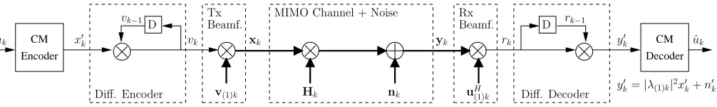
Figure 1 shows the simplified block diagram of the differen-tially encoded CM assisted eigen-beamforming scheme. A sequence of information symbols {uk}, where the subscript k denotes the
time index, are first CM-encoded to generate the sequence {x′ k},
before entering the differential encoder, where the sequence {vk}
is produced. At the transmit beamforming block of Figure 1, vk
is multiplied by the beamforming weight vector v(1)k in order to
produce xk, where v(1)k is the first column vector of the unitary
CM Decoder Encoder
CM
D D
uk uˆk
Diff. Encoder
y′ k
vk−1 rk−1
y′
k=|λ(1)k|2x′k+n′k
Tx Beamf. vk
Rx Beamf.
Diff. Decoder rk
yk
xk
MIMO Channel + Noise
x′ k
v(1)k Hk nk u
[image:2.595.59.562.51.126.2]H (1)k
Fig. 1. The simplified block diagram of differentially-encoded CM assisted eigen beamforming system.
beamforming is carried out with the aid of the beamforming weight vector ofuH(1)k, which is the conjugate transpose of the first column vector of the unitary matrix U in (3). Then differential decoding is carried out, followed by CM decoding as seen in Figure 1. By ignoring the time indexk, the signal input to the differential decoder can be simplified as:
r = uH(1)y ,
= uH(1)Hv(1)v+u H (1)kn ,
= λ(1)v+ ˘n , (4)
where we have uH
(1)Hv(1) = uH(1)UDVHv(1) = λ(1) and n˘ =
uH(1)kn. Note thatλ(1)is the first diagonal value of the matrixDin
(3), which is also the first and the largest eigenvalue of the matrix
H. Hence, the combined transmit and receive beamforming scheme has converted a MIMO channel into a Single-Input Single-Output (SISO) channel having a single channel coefficient given by λ(1).
The variance of the Additive White Gaussian Noise (AWGN) n˘ is the same as that of the original AWGNn, which is given byN0.
Note however that, when the predicted channelHˆ is insufficiently accurate, the signal subspaces defined by the unitary matricesUˆ and
ˆ
VofHˆ = ˆUDˆVˆH are no longer unique [18]. More specifically, we have [19]:
ˆ
u(1)= ˜u(1)ejθ1; ˆv(1)= ˜v(1)ejθ2 , (5)
whereu˜(1)=|uˆ(1)|andv˜(1)=|vˆ(1)|. The phase-ambiguity values
incurred in the estimated eigen-vectors ofuˆ(1)andvˆ(1)wereθ1 and
θ2, respectively. Let us now demonstrate how this phase-ambiguity
may be resolved with the aid of differential encoding [20].
The differential encoder is shown between the CM encoder and the transmit beamformer in Figure 1. As seen in Figure 1, the differentially encoded symbol vk transmitted at time instant k is
obtained from:
vk=x′kvk−1 , (6)
where x′
k is a CM encoded symbol and vk−1 is the symbol
trans-mitted at time instant (k−1) [17]. Let us employ PSK-based CM schemes, where we have |x′
k|2 = |vk|2 = 1 and assume that the
channel coefficient λ(1) in (4) is constant across during the time
instants k and (k−1). Upon introducing the time indexk in (4), with the aid of (6) we have:
y′
k = rkrk∗−1 ,
= |λ(1)k|2vkvk∗−1+λ(1)kvk˘n∗k−1+
λ∗
(1)k−1v∗k−1˘nk+ ˘nkn˘∗k−1 ,
y′
k = |λ(1)k|2x′k+n′k, (7)
where the superscript ∗ denotes the complex conjugate operation. Hence, an additional differential encoding and decoding pair in an eigen-beamforming scheme is another SISO channel having a channel coefficient of |λ(1)k|2 and an AWGN of n′k = λ(1)kvkn˘∗k−1 +
λ∗
(1)k−1vk∗−1n˘k+ ˘nk˘n∗k−1. The variance of the AWGNn′k is given
by2|λ(1)k|2N0. Note in (7) that the equivalent channel coefficient of
a differentially encoded eigen-beamformer is|λ(1)k|2. Hence, when
the predicted MIMO channel is inaccurate, we have:
|λˆ(1)|2 =
ˆuH(1)Hvˆ(1)
2
, (8)
= (˜uH(1)e−jθ1)H(˜v(1)ejθ2)
2
,
= ˜uH(1)Hv˜(1)
2
· |ej(θ2−θ1)|2 ,
= ˜uH(1)Hv˜(1)
2
, (9)
where the phase-ambiguity inherent in the eigen-vectors is now removed. Since we do not knowHin (8), we may obtain an estimate of|ˆλ(1)|2 in (8) using (4) as follows:
|ˆλ(1)|2 = rr∗,
= (λ(1)v+ ˘n)(λ(1)v+ ˘n)∗,
= λ(1)
2
+λ(1)v˘n∗+λ∗(1)v∗˘n . (10)
Note that we can also acquire |λˆ(1)|2 by substituting Hˆ into (8).
However, we found that the estimated value in (10) is more accurate. The logarithmic-domain channel soft-metric can be computed at the soft demodulator within the CM decoder as:
P r(y′
k|x′k=x′
(m)) = −
yk′ − |ˆλ(1)k|2x′(m)
2
2|λˆ(1)k|2N0
, (11)
wherex′(m), for m ∈ {0,1, . . . , M−1}, is themth phasor in an
M-ary PSK modulation constellation.
III. MIMO CHANNELPREDICTION
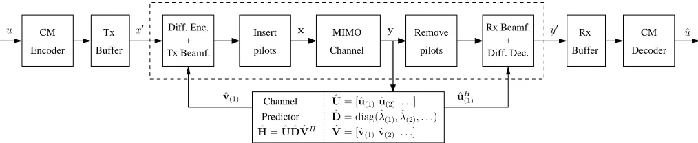
The block diagram of the channel prediction aided differentially encoded CM assisted eigen-beamforming scheme is shown in Fig-ure 2, where (ˆ.) denotes the predicted value of (.). Transmit and receive buffers are used for buffering a CM-encoded frame, which is partitioned into shorter subframes andMt number of pilot symbols
are attached to each subframe at its beginning as seen in Figure 2. A shorter subframe length is expected to increase the accuracy of the channel predictor, but naturally, it also imposes a higher pilot symbol overhead. During the transmission of the pilot symbols only one transmit antenna is activated for the corresponding symbol period, while the remaining transmit antennas are deactivated [13], [14], as seen in Figure 3.
Let us denote the index of the subframe by the subscriptland the time index bymt for reasons of brevity in this section. For thelth
subframe transmitted at time instantmt(1≤mt≤MT), the signal
ymr(l, mt)received by themr-th(1≤mr≤MR)receiver antenna is given by:
ymr(l, mt) = hmrmt(l, mt)xp+nmr(l, mt), (12)
wherep is the predictor order,hmrmt(l, mt)represents the fading channel coefficient between themt-th transmit antenna and themr
-th receive antenna for -thelth subframe at time instantmt, whilexp
represents the pilot symbol, which is assumed to be the same for all transmit antennas and for all subframes. Furthermore, nmr(l, mt) is the AWGN contribution at the mrth receiver antenna for thelth
pilots
Insert MIMO
Channel
Remove
pilots
Rx
Buffer Buffer
Tx CM
Decoder CM
Encoder
Diff. Enc. +
Diff. Dec. + Rx Beamf.
Tx Beamf.
Channel
Predictor
u x′ y′ uˆ
ˆ
V= [ˆv(1)ˆv(2) . . .]
ˆ uH
(1) ˆ
v(1)
x y
ˆ
U= [ˆu(1)uˆ(2) . . .] ˆ
H= ˆUDˆVˆH
ˆ
[image:3.595.53.560.53.157.2]D= diag(ˆλ(1),ˆλ(2), . . .)
Fig. 2. The block diagram of the channel prediction aided differential CM assisted eigen-beamforming system.
0
0
0
0
0
0
P
D
D
P
P
D
D
D
D
D
D
0
0
0
0
0
0
P
D
D
P
P
D
D
D
D
D
D
0
0
0
0
0
0
P
D
D
P
P
D
D
D
D
D
D
Subframe length
Frame length (a frame of two subframes)
Number of
transmit
antennas
· · ·
· · ·
· · ·
. ..
· · ·
· · ·
· · ·
...
. ..
...
. ..
· · ·
· · ·
· · ·
. ..
· · ·
· · ·
· · ·
...
. ..
...
. ..
· · ·
· · ·
· · ·
. ..
· · ·
· · ·
· · ·
...
. ..
...
. ..
Fig. 3. The MIMO transmission format, where the notationsP,Dand0denote the pilot symbol, data symbol and zero-energy symbol, respectively.
With the aid of theMt-by-Mtpilot symbol matrix seen in Figure 3,
the (Mr×Mt)-dimensional MIMO channel prediction problem is
decomposed into a SISO channel prediction scenario, where any classic SISO channel prediction algorithm can be applied directly. In this contribution, MMSE based narrowband channel prediction is invoked [16]. Specifically, we construct the followingp-dimensional vector:
ymr(l, mt) = [ymr(l−p+ 1, mt) · · · ymr(l, mt)]
T .
(13)
If we assign the value of “+1” to each pilot symbol, then the channel coefficient corresponding to themt-th pilot symbol of the (l+ 1)-th
subframe is given by the corresponding received pilot symbolymr(l+
1, mt) =hmr(l+ 1, mt)·(+1)in the absence of noise. Hence, the
predicted channel coefficient corresponding to themt-th pilot symbol
for the (l+ 1)-th subframe, namelyyˆmr(l+ 1, mt), can be estimated
based on the received pilot symbol vector of thel-th subframe as [15]:
ˆ
ymr(l+ 1, mt) = d0ymr(l, mt) , (14)
whered0 is formulated as [15]:
d0=R−ymr1 (l,mt)rymr(l,mt)ymr(l+1,mt) , (15) whereRymr(l,mt) is the(p×p)-dimensional autocorrelation matrix ofymr(l, mt), which is given by [15]:
Rymr(l,mt)=E[ymr(l, mt)y
H
mr(l, mt)]. (16) Furthermore, rymr(l,mt)ymr(l+1,mt) is the p-dimensional cross-correlation vector recorded forymr(l, mt)andymr(l+1, mt), which
is given by [15]:
rymr(l,mt)ymr(l+1,mt)=E[y
∗
mr(l, mt)ymr(l+ 1, mt)]. (17)
Finally, the predicted channel coefficients corresponding to the data symbol can be obtained with the aid of linear interpolation [21].
IV. SIMULATIONRESULTS
Let us consider transmissions over correlated Rayleigh fading channels having a normalised Doppler frequency of 10−3
and a subframe length of Ls = 100 CM-encoded symbols as well as a
frame length of Lf = 1000 CM-encoded symbols, unless stated
otherwise. The predictor order is fixed top= 10. Coherently detected CM or Differential-encoded CM (D-CM) schemes will be employed. The number of transmit antennas is fixed toMt= 2and the number
of receive antennas is fixed to Mr = 2. The block diagram of a
coherently detected CM assisted eigen-beamforming system is the same as that seen in Figure 1, albeit without the differential encoder and decoder blocks. The pilot overhead is given byMt/(Mt+Ls),
which is1.96%, when usingMt= 2 andLs= 100.
For the sake of a fair comparison, both of the CM schemes employed were configured to have a similar decoding complexity quantified in terms of the total number of trellis decoding states. More quantitatively, for the non-iterative TCM or BICM code of memory ν, the corresponding complexity is proportional to the number of decoding states S = 2ν. Since TTCM schemes invoke two TCM
component codes, a TTCM code employingtiterations and using an S-state component code exhibits a complexity proportional to2.t.S ort.2ν+1states. As for BICMID schemes, only one decoder is used,
but the demodulator is invoked in each decoding iteration. However, the complexity of the demodulator is assumed to be insignificant compared to that of the trellis decoder. Hence, a BICMID code em-ployingtiterations and using anS-state code exhibits a complexity proportional tot.S ort.2M
. For these reasons, we opted forS= 64
for the TCM and BICM schemes while S = 8 and t = 4 for the TTCM scheme, as well asS= 8andt= 8for the BICMID scheme. The code polynomials used for the CM schemes can be found on pages 775, 792 and 798 in [16].
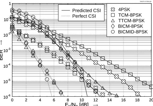
Figure 4 shows the Bit Error Ratio (BER) versus Signal-to-Noise Ratio (SNR) per bit, namelyEb/N0, performance of the 4PSK and
CM-8PSK assisted eigen-beamforming schemes, when employing either perfect or predicted CSI without differential encoding. Hence, as we can see from Figure 4, the performance of the coherently detected scheme suffers from a significant degradation, when the CSI is imperfect. For example, at BER=10−5
0 2 4 6 8 10 12 14 16 18 20 Eb/N0[dB]
10-6 10-5 10-4 10-3 10-2 10-1 1
BER
0 2 4 6 8 10 12 14 16 18 20
Eb/N0[dB] 10-6
10-5 10-4 10-3 10-2 10-1 1
BER
4PSK TCM-8PSK TTCM-8PSK BICM-8PSK BICMID-8PSK Predicted CSI
[image:4.595.51.297.53.223.2]Perfect CSI
Fig. 4. BER versusEb/N0 performance of the 4PSK (Lf =Ls = 100) and CM-8PSK (Lf = 1000, Ls = 100) beamforming schemes, when communicating over correlated Rayleigh fading channels having a normalised Doppler frequency of10−3. The pilot overhead is 1.96%.
have the same effective throughput of 2 bit/symbol. Interestingly, in the context of the eigen-beamforming system, the BICMID-8PSK assisted scheme outperformed the other three CM-8PSK assisted schemes, although when communicating over SISO Rayleigh fading channels without beamforming, BICMID-8PSK is outperformed by the TTCM-8PSK scheme [16].
beamfdiff-cm-2bps.gle
0 2 4 6 8 10 12 14 16 18 20
Eb/N0[dB]
10-6 10-5 10-4 10-3 10-2 10-1 1
BER
0 2 4 6 8 10 12 14 16 18 20
Eb/N0[dB] 10-6
10-5 10-4 10-3 10-2 10-1 1
BER
D-4PSK D-TCM-8PSK D-TTCM-8PSK D-BICM-8PSK D-BICMID-8PSK Predicted CSI
[image:4.595.313.562.211.378.2]Perfect CSI
Fig. 5. BER versusEb/N0performance of the D-4PSK (Lf =Ls= 100) and D-CM-8PSK (Lf = 1000, Ls = 100) beamforming schemes, when communicating over correlated Rayleigh fading channels having a normalised Doppler frequency of10−3. The pilot overhead is 1.96%.
Figure 5 shows the performance of the D-4PSK and D-CM-8PSK assisted eigen-beamforming schemes, when employing either perfect or predicted CSI. As we can see from Figure 5, the Eb/N0
performance loss due to employing imperfect CSI is only about 2 dB at BER=10−5
for all CM schemes. This is because the differential coding is effective in circumventing the phase-ambiguity problem. However, the employment of differential coding comes at the penalty of increasing the noise variance fromN0to2|λ(1)k|2N0, as discussed
in Section II. As a result, when the CSI is perfect, the performance of the D-CM-8PSK schemes characterised in Figure 4 is about 3 dB inferior to that of the CM-8PSK schemes featuring in Figure 5. How-ever, as we can see from Figure 6, when the CSI is imperfect, the D-CM-8PSK scheme performs better than the D-CM-8PSK arrangement, despite having a higher noise variance. For example at BER=10−5,
the D-BICMID-8PSK and D-TCM-8PSK schemes perform about 1 dB and 3 dB better than their coherently detected non-differential counterparts. Furthermore, the uncoded D-4PSK scheme was unable
to outperform the uncoded 4PSK scheme, as evidenced in Figure 5, when the CSI was imperfect. These findings underline the importance of using error correction schemes in practical eigen-beamforming schemes. More specifically, observe in Figures 4 and 5 that at a BER of10−5, the D-BICMID-8PSK scheme attained a coding gain
of about 6.5 dB and 9.5 dB over the 4PSK and D-4PSK schemes, respectively, when using predicted CSI. Note that the CM schemes employed were suboptimum, since they were originally designed for coherently detected non-differential modulation, nonetheless, their concatenation with differential coding yielded attractive performance gains in the context of realistically predicted CSI. Hence, our future work will consider the design of differentially encoded modulation based CM schemes for the sake of achieving a higher coding gain.
beamfdiffcmp-cm-2bps.gle
0 2 4 6 8 10 12 14 16 18 20
Eb/N0[dB]
10-6 10-5 10-4 10-3 10-2 10-1 1
BER
0 2 4 6 8 10 12 14 16 18 20
Eb/N0[dB] 10-6
10-5 10-4 10-3 10-2 10-1 1
BER
4PSK TCM-8PSK TTCM-8PSK BICM-8PSK BICMID-8PSK D-CM
CM
Fig. 6. BER versusEb/N0 performance of the 4PSK (Lf =Ls= 100) and CM-8PSK (Lf = 1000, Ls = 100) beamforming schemes with and without differential coding, when communicating over correlated Rayleigh fading channels having a normalised Doppler frequency of10−3with the aid of an MMSE channel predictor. The pilot overhead is 1.96%.
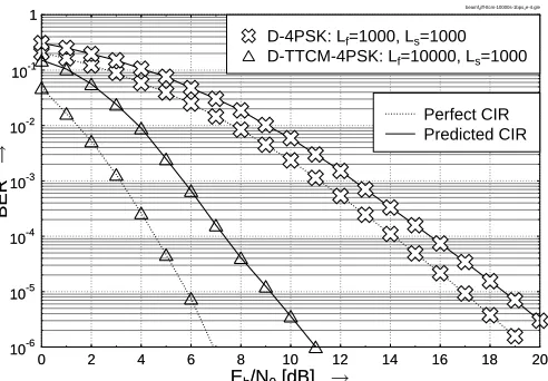
Let us now study the effect of different channel fading rates in the context of Figures 7 and 8, where the normalised Doppler frequencies of the channels were 10−3 and 10−4, respectively. As seen from
Figures 7 and 8, when the normalised Doppler frequency of the channel was reduced by a factor of 10, it becomes possible to increase the subframe/frame length by a factor of 10, while maintaining a similar performance.
beamfdiff-ttcm-1000s-1bps.gle
0 2 4 6 8 10 12 14 16 18 20
Eb/N0[dB]
10-6 10-5 10-4 10-3 10-2 10-1 1
BER
0 2 4 6 8 10 12 14 16 18 20
Eb/N0[dB] 10-6
10-5 10-4 10-3 10-2 10-1 1
BER
D-4PSK: Lf=100, Ls=100
D-TTCM-4PSK: Lf=1000, Ls=100
Perfect CIR Predicted CIR
Fig. 7. BER versusEb/N0performance of the D-4PSK and D-TTCM-4PSK Beamforming schemes, when communicating over correlated Rayleigh fading channels having a normalised Doppler frequency of10−3. The pilot overhead is 1.96%.
[image:4.595.313.562.518.686.2]D-CM-beamfdiff-ttcm-10000s-1bps1e-4.gle
0 2 4 6 8 10 12 14 16 18 20
Eb/N0[dB]
10-6 10-5 10-4 10-3 10-2 10-1 1
BER
0 2 4 6 8 10 12 14 16 18 20
Eb/N0[dB] 10-6
10-5 10-4 10-3 10-2 10-1 1
BER
D-4PSK: Lf=1000, Ls=1000
D-TTCM-4PSK: Lf=10000, Ls=1000
[image:5.595.52.298.52.223.2]Perfect CIR Predicted CIR
Fig. 8. BER versusEb/N0performance of the D-4PSK and D-TTCM-4PSK Beamforming schemes, when communicating over correlated Rayleigh fading channels having a normalised Doppler frequency of10−4. The pilot overhead is 0.2%.
beamfdiff-ttcm4psk-10000s.gle
0 2 4 6 8 10 12 14 16 18 20
Eb/N0[dB]
10-6 10-5 10-4 10-3 10-2 10-1 1
BER
0 2 4 6 8 10 12 14 16 18 20
Eb/N0[dB] 10-6
10-5 10-4 10-3 10-2 10-1 1
BER
D-4PSK: Lf=100, Ls=100
D-TTCM-4PSK: Lf=10000, Ls=100
D-TTCM-4PSK: Lf=10000, Ls=200
D-TTCM-4PSK: Lf=10000, Ls=20
[image:5.595.50.298.262.436.2]Perfect CIR Predicted CIR
Fig. 9. BER versus Eb/N0 performance of the D-4PSK and D-TTCM-4PSK Beamforming schemes, when communicating over correlated Rayleigh fading channels having a normalised Doppler frequency of10−3. The pilot overheads are 1.0%, 1.96% and 9.1% when employing Ls = 200, 100 and 20, respectively.
4PSK assisted eigen-beamformer in Figure 9. As we can see from Figure 9, when the subframe length is reduced the accuracy of the channel predictor improves, which resulted in a better performance at the cost of a higher pilot symbol overhead. As an example, there areLf/Ls= 500subframes of lengthLs= 20data symbols in the
Lf = 10′000D-CM-4PSK symbol frame, resulting in a pilot symbol
overhead of 9%. By contrast, whenLf is fixed to 10’000, the pilot
symbol overheads imposed by having Ls = 200 and Ls = 100
are about 1% and 2%, respectively. We infer from Figure 9 that usingLs= 100constitutes a good compromise in terms of the BER
performance versus pilot symbol overhead trade-offs.
V. CONCLUSIONS
In this contribution, we have studied a channel prediction aided coded modulation assisted eigen-beamforming scheme communi-cating over correlated Rayleigh fading channels. It was shown in Figure 6 that both differential coding and coded modulation yielded benefits in terms of assisting an eigen-beamformer employing a pilot-based channel predictor. An open research problem is the design of new rotationally invariant coded modulation schemes for further improving the performance of realistic eigen-beamformers using pilot-based predicted channel state information.
REFERENCES
[1] G. Foschini Jr. and M. Gans, “On limits of wireless communication in a fading environment when using multiple antennas,” Wireless Personal
Communications, vol. 6, pp. 311–335, March 1998.
[2] E. Telatar, “Capacity of multi-antenna Gaussian channels,” European
Transactions on Telecommunication, vol. 10, pp. 585–595, Nov–Dec
1999.
[3] V. Tarokh, N. Seshadri and A. R. Calderbank, “Space-time codes for high rate wireless communication: Performance analysis and code construc-tion,” IEEE Transactions on Information Theory, vol. 44, pp. 744–765, March 1998.
[4] S. M. Alamouti, “A Simple Transmitter Diversity Scheme for Wireless Communications,” IEEE Journal on Selected Areas in Communications, vol. 16, pp. 1451–1458, October 1998.
[5] F. Rashid-Farrokhi, K. Liu, and L. Tassiulas, “Transmit beamforming and power control for cellular wireless systems,” IEEE Journal on Selected
Areas in Communications, vol. 16, pp. 1437–1450, October 1998.
[6] A. Abdel-Samad, T. N. Davidson and A. B. Gershman, “Robust transmit eigen beamforming based on imperfect channel state information,” IEEE
Transactions on Signal Processing, vol. 54, pp. 1596–1609, May 2006.
[7] G. Ungerb¨ock, “Channel coding with multilevel/phase signals,” IEEE
Transactions on Information Theory, vol. 28, pp. 55–67, January 1982.
[8] C. Berrou, A. Glavieux and P. Thitimajshima, “Near Shannon Limit Error-Correcting Coding and Decoding : Turbo Codes,” in Proceedings,
IEEE International Conference on Communications, pp. 1064–1070,
1993.
[9] P. Robertson, T. Wo¨rz, “Bandwidth-efficient Turbo Trellis-coded Mod-ulation Using Punctured Component Codes,” IEEE Journal on Selected
Areas in Communications, vol. 16, pp. 206–218, February 1998.
[10] E. Zehavi, “8-PSK trellis codes for a Rayleigh fading channel,” IEEE
Transactions on Communications, vol. 40, pp. 873–883, May 1992.
[11] G. Caire, G. Taricco and E. Biglieri, “Bit-Interleaved Coded Modula-tion,” IEEE Transactions on Information Theory, vol. IT-44, pp. 927– 946, May 1998.
[12] X. Li, J. A. Ritcey, “Trellis-Coded Modulation with Bit Interleaving and Iterative Decoding,” IEEE Journal on Selected Areas in
Communi-cations, vol. 17, pp. 715–724, April 1999.
[13] Z. Luo, H. Gao, Y. Liu, and J. Gao, “Robust pilot-symbol-aided MIMO channel estimation and prediction,” in IEEE Global Telecommunications
Conference, (Dallas, Texas, USA), pp. 3646 – 3650, 29 November - 3
December 2004.
[14] D. V. Duong, B. Holter, and G. E. Oien, “Optimal pilot spacing and power in rate-adaptive MIMO diversity systems with imperfect transmitter CSI,” in IEEE 6th Workshop on Signal Processing Advances
in Wireless Communications, (New York, USA), pp. 47 – 51, 5 - 8 June
2005.
[15] A. Duel-Hallen, S. Hu, and H. Hallen, “Long range prediction of fading signals: enabling adaptive transmission for mobile radio channels,” IEEE
Signal Processing Magzine, vol. 17, pp. 62–75, May 2000.
[16] L. Hanzo, S. X. Ng, W. Webb and T.Keller, Quadrature Amplitude
Modulation: From Basics to Adaptive Trellis-Coded, Turbo-Equalised and Space-Time Coded OFDM, CDMA and MC-CDMA Systems, Second Edition. New York, USA : John Wiley and Sons, 2004.
[17] B. Vucetic and J. Yuan, Space-Time Coding. New York: John Wiley-IEEE Press, May 2003.
[18] H. T. Nguyen, G. Leus, and N. Khaled, “Prediction of the eigenvectors for spatial multiplexing MIMO systems in time-varying channels,” in
Proceedings of the Fifth IEEE International Symposium on Signal Processing and Information Technology, (Athens, Greece), pp. 119– 124,
18 - 21 December 2005.
[19] J. Liu and A. Host-Madsen, “Novel communication schemes with blind channel estimation in TDD MIMO system,” in Proceedings of the
International Conference on Acoustics Speech and Signal Processing,
no. 2, pp. II–33 – II–36, 2004.
[20] T. Dahl, N. Christophersen, and D. Gesbert, “Blind MIMO eigenmode transmission based on the algebraic power method,” IEEE Transactions
on Signal Processing, vol. 52, pp. 2424– 2431, September 2004.
[21] S. Coleri, M. Ergen, A. Puri, and A. Bahai, “Channel estimation techniques based on pilot arrangement in OFDM systems,” IEEE