Optimization of plasma amplifiers
James D. Sadler,1Raoul M. G. M. Trines,2Max Tabak,3Dan Haberberger,4Dustin H. Froula,4Andrew S. Davies,4 Sara Bucht,4Luís O. Silva,5E. Paulo Alves,6Frederico Fiúza,6Luke Ceurvorst,1Naren Ratan,1Muhammad F. Kasim,1
Robert Bingham,2,7and Peter A. Norreys1,2
1Clarendon Laboratory, University of Oxford, Parks Road, Oxford OX1 3PU, United Kingdom 2Central Laser Facility, STFC Rutherford Appleton Laboratory, Didcot, Oxon OX11 0QX, United Kingdom
3Lawrence Livermore National Laboratory, 7000 East Ave., Livermore, California 94550-9234, USA 4Laboratory for Laser Energetics, 250 East River Road, Rochester, NY 14623-1299, USA 5GoLP/IPFN, Instituto Superior Tecnico, Universidade de Lisboa, 1049-001 Lisbon, Portugal 6HED Science Division, SLAC National Accelerator Laboratory, Menlo Park, California 94025, USA 7Department of Physics, University of Strathclyde, 107 Rottenrow East, Glasgow G4 0NG, United Kingdom
(Received 16 September 2016; revised manuscript received 16 January 2017; published 24 May 2017)
Plasma amplifiers offer a route to side-step limitations on chirped pulse amplification and generate laser pulses at the power frontier. They compress long pulses by transferring energy to a shorter pulse via the Raman or Brillouin instabilities. We present an extensive kinetic numerical study of the three-dimensional parameter space for the Raman case. Further particle-in-cell simulations find the optimal seed pulse parameters for experimentally relevant constraints. The high-efficiency self-similar behavior is observed only for seeds shorter than the linear Raman growth time. A test case similar to an upcoming experiment at the Laboratory for Laser Energetics is found to maintain good transverse coherence and high-energy efficiency. Effective compression of a 10 kJ, nanosecond-long driver pulse is also demonstrated in a 15-cm-long amplifier.
DOI:10.1103/PhysRevE.95.053211
I. INTRODUCTION
Solid-state-grating pulse compressors are used in many petawatt laser systems to reduce the duration of a long chirped pulse. Due to their damage thresholds and considerations of pulse quality, the incident fluence is limited. The cost and complexity of the meter-scale compressors poses a significant challenge for the proliferation and advancement of petawatt sources. The grating technology is mature, with advanced systems at LLNL [1] and OMEGA EP [2] giving high efficiency and phase control.
Optical parametric chirped pulse amplifiers (such as the Vulcan 10 PW project [3]) promise power improvements in femtosecond pulses but will also still be limited by the final compressor.
Continued development towards higher intensity pulses is motivated by applications in ultrarelativistic laser plasma experiments. For example, it was predicted that virtual pairs will produce vacuum birefringence [4], and solid targets will generate macroscopic matter-antimatter plasmas and kilojoules of gamma photons under irradiation approaching 1024W/cm2. This will require laser powers up to 100 PW.
High-power laser pulses are also used to drive secondary sources such as betatron x-ray emission, GeV electron beams and neutron beams [5]; however, the repetition rate must be improved in order to compete with conventional technology. This could be better facilitated by plasma optics and com-pressors as there is no degradation over time. Better laser pulse compression would therefore lead to improvements in technology and advances in basic science concerning quantum-plasma effects and pair production.
Laser pulse compression in a plasma [6] will permit orders of magnitude reduction in size and cost of the compression medium. In addition, the requirements on the stretched pulse are greatly reduced as it is used only as a driver, in contrast
to nonlinear optics methods with strict beam requirements. These facts could facilitate scaling to currently infeasible pulse powers. Finally, Raman backward scattering is scale invariant with wavelength and therefore compresses long ultraviolet pulses as effectively as infrared light, a clear advantage over gratings. High-energy ultraviolet short pulses would dramatically lower the requirements for inertial confinement fusion. The fast ignition scheme intends to ignite a compressed fusion fuel pellet within the 30 ps before it disassembles [7,8]. However, efficient laser to fuel coupling is realistic only using these shorter wavelengths.
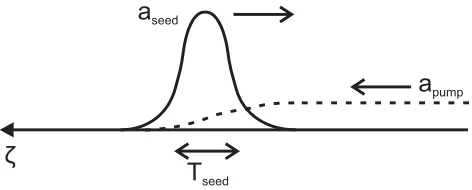
The Raman amplifier scheme, illustrated in Fig.1, transfers energy from the long pump pulse, frequency ω, to the short counterpropagating seed pulse. This is achieved by overlapping the pulses in an underdense plasma to excite beneficial Raman backward scattering. A counterpropagating geometry maximizes the interaction length as well as the instability growth rate. The seed frequency is downshifted from the pump by the plasma frequencyωp=ne2/(0me), where nncrit/100 is the plasma electron number density,
ncrit is the critical plasma density, and other symbols have their usual meanings. As a result, the beating of the two waves at frequencyωpwill resonantly excite an electron plasma wave through the ponderomotive force. The plasma wave has a slow phase speed of approximately cωp/(2ω) and a wavelength approximately half that of the pump pulse. The pump pulse will then scatter from the plasma wave and amplify the shorter pulse, reaching powers greatly in excess of its pump pulse.
Previous studies have verified the high-energy transfer efficiency with a variety of numerical methods and approxima-tions [9–11]; however, a full prescription of optimal parameters (including the short seed pulse) is needed. In this paper we present the first extensive numerical study that uses a fully kinetic code to assess the amplifier efficiency across all three
T
seedζ
[image:2.612.59.295.72.167.2]a
pumpa
seedFIG. 1. Schematic of the Raman amplifier scheme in an under-dense plasma, where the long pump pulse (dashed) counterpropagates with a short seed pulse (solid line) downshifted from the pump by the plasma frequency. To achieve high-energy transfer and pump depletion, as shown here, Eq. (4) must be satisfied.
main parameters. These are the pump pulse intensity, the plasma electron density, and electron temperature. The perfor-mance is limited by kinetic effects across a large region of the parameter space. However, even with temperatures typical of experimental preformed plasmas, high efficiency is achievable. We then present a further performance improvement based on tailoring the seed pulse.
The self-similar solution of Malkinet al.[6,12] gives the seed pulse envelope and its evolution in the advanced nonlinear amplification stage. The seed power greatly exceeds the pump pulse power, the pump is significantly depleted, and the energy transfer converges to a constant rate. The condition for this behavior can be simply derived from the coupled envelope equations for the three-wave process [6,13]:
2∂apump
∂ζ =ωpaLaseed, (1a)
∂aL
∂ζ = −ωapumpaseed∗ /2, (1b)
∂aseed
∂t = −ωpaL∗apump, (1c)
where (for linear polarization)aseed=8.55×10⁻¹⁰
Iseedλ2μm is the dimensionless seed pulse peak amplitude, with the peak intensity Iseed(t) in units W/cm2,apump is the same for the pump pulse, andaLis the Langmuir plasma wave amplitude normalized tomecωp/e. The equations are taken in the moving frame such thattis the propagation time andζ =t+x/cis the coordinate in the frame moving with the seed pulse. We have neglected the temporal derivatives in the first two equations,
∂apump
∂ζ
∂apump
∂t , (2)
thus finding the behavior in the limit that the seed pulse duration is much shorter than its time scale of evolution. The approximate solution is found by taking a constant real amplitude seed pulse. We may find the time taken for full pump depletion by differentiating (1a) and substituting Eq. (1b) to give
∂2a pump
∂ζ2 +
ωωp
4 a 2
seedapump=0. (3)
The solution is apump(ζ)=apump(0) cos(√ωωpaseedζ/2), meaning full pump depletion is achieved at the first zero when
aseedTseed√ωωpπ, whereTseed is the seed pulse duration given by the full width at half maximum of the power envelope. Importantly, it is a condition on the seed pulse only, suggesting that achieving high efficiency from the start of the amplifier requires careful preparation of an intense seed pulse. The more thorough self-similar derivation [6,13] gives
aseedTseed√ωωp 5. (4)
This condition is an attractor; once it is met, it continues to hold throughout the nonlinear regime. The pulse therefore shortens and gains bandwidth as its intensity grows, typically to subpicosecond duration. Experimental attempts have had some success in reaching this nonlinear behavior; however, none have achieved the full potential of the scheme [14–18].
II. OPTIMAL EFFICIENCY
The efficiency theoretically converges to a value of 1−ωp/ω in the nonlinear regime, found from the Manley-Rowe relations [19]. In practice, plasma kinetic effects will cause a convergence to a lower value [20,21]. These effects are heavily dependent on the laser dimensionless amplitude, plasma electron density, and temperature.
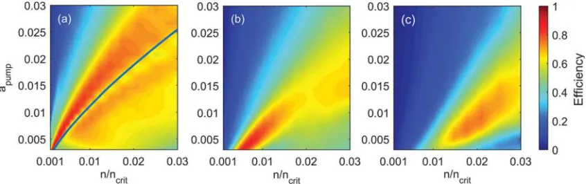
Figure 2 indicates the limited efficiency, as found from 1200 one-dimensional particle-in-cell (PIC) simulations cov-ering the parameter space. These simulations initialize a large number of macroparticles, each representing many electrons. These evolve according to their self-consistent electromagnetic fields which are calculated on a Cartesian grid. As such, there are no appreciable approximations to the physics apart from artificial noise levels and the available grid resolution. These simulations accurately model kinetic effects and relativistic corrections, but the following loss mechanisms are not included: collisional damping, competing plasma instabilities of the seed pulse, and spontaneous Raman and Brillouin scattering of the pump pulse before it encounters the seed.
The pump dimensionless amplitude apump and plasma density were constant in each simulation, and the seed pulse initially met the nonlinear condition (4) with dimensionless amplitude aseed=0.1 and central frequency ω−ωp. The
efficiency is defined as the change in seed energy divided by the total pump energy it has propagated through, taken at a time when this has converged to a constant value. Only the energy of the main amplified spike was considered, neglecting any prepulse or trailing secondary spikes. Neutralizing ions were kept static, and the seed and pump polarisations were linear and aligned. Simulations used the code OSIRIS [22] with 60 cells and 480 particles per wavelength with cubic interpolation.
FIG. 2. Simulated energy transfer efficiency of Raman compression, including kinetic effects, for the three different electron temperatures of (a) 0 eV, (b) 100 eV, and (c) 400 eV. The plots show the maximal amplifier efficiency in the nonlinear regime, as found from 1200 one-dimensional particle-in-cell simulations covering the parameter space. The pump pulse dimensionless amplitude isapumpand the plasma
electron densitynis normalized to the pump pulse critical density. Above the theoretical Langmuir wave-breaking threshold for cold plasma (blue solid line), the amplifier efficiency rapidly decreases.
the numerical heating is>1000ω−1
p , but the amplified pulse
encounters newly initialized plasma after just 20ω−1
p . This was
confirmed with observation of the macroparticle phase space diagrams.
Particle-trapping effects may also be overestimated as a result of the accumulation of interpolation errors. This increases the spread of particle momentum, thus artificially increasing the likelihood of a macroparticle becoming trapped in the plasma wave [23]. As a result, higher order interpolation methods reduce this source of error, so a cubic interpolation technique was employed. To verify convergence, several simulations were repeated with 10 times the particle number, with only minor differences seen in the low-power trailing parts of the amplified pulse. Since the high-power main peak is of primary interest for an amplifier, the particle number employed for the main parameter scan is sufficient. The final pulse energies agreed to within 5%.
When the plasma wave is overdriven, a large proportion of electrons exceed the wave phase velocity and the wave will become turbulent and break, ending the energy transfer [11]. This will occur [24] for pump dimensionless amplitudes aboveapump=0.35(n/ncrit)0.75, shown by the solid blue line on the cold plasma case in Fig.2. Beyond this threshold, the amplifier efficiency rapidly decreases [25–27], also consistent with recent Vlasov simulations [28]. For a given density, the peak efficiency is close to 1−ωp/ωand occurs slightly beyond the theoretical wave-breaking threshold.
For increasing electron temperature, the wave-breaking threshold decreases due to the distribution having a larger number of particles exceeding the plasma wave’s phase velocity [29]. This effect was clear when the study was repeated with electron temperatures 100 and 400 eV, shown in Figs. 2(b) and 2(c). The optimal region is localized and is a strong function of temperature, suggesting good characterization and control of experimental plasma condi-tions is necessary. Furthermore, temperature increases due to collisional damping of the pump pulse must be considered.
For higher temperatures, thermal motion of the electrons can also cause particle trapping, and the plasma wave is Landau damped. This limits the optimal region towards regions of higher plasma density, where the plasma wave phase velocity
is greater. The analytical condition that the wave phase velocity greatly exceeds the electron thermal velocity yieldsn/ncrit 4KBT /(mec2). This is well matched to the regions of highest efficiency at temperatures 100 and 400 eV.
Considering Fig.2, there is a clear advantage to maintaining a low temperature, as a wider range of plasma density is then accessible. Many studies [30–35] have focused on the scheme where the pump or a prepulse ionizes and heats the plasma, ruling out the benefits of a low-temperature interaction. A promising alternative is to keep the pump below the ionization threshold, so the plasma is only ionized once the higher intensity seed arrives [36,37]. The seed duration is similar to the electron thermalization time, so the effective longitudinal temperature of the interaction is low compared to the pump ionization scheme. There is also the added benefit of minimizing the ionized volume, which reduces losses and unwanted prepulse from premature pump back-scatter [38,39].
III. OPTIMAL SEED PULSE
Following Trines et al.[13] we now present a numerical investigation to optimize the initial seed pulse duration. We assumed the typical experimental constraint of constant seed pulse energy (i.e., constantaseed2 Tseed) and constant bandwidth. Subject to these constraints one can always lengthen the seed until it satisfies Eq. (4) or choose a shorter, more intense pulse, right down to its bandwidth-limited duration. It is shown here that, for experimentally relevant conditions, the optimal performance is obtained for the shortest seed pulses.
In neglecting temporal derivatives [Eq. (2)], the derivation of the nonlinear behavior assumed a seed pulse shorter than the characteristic growth time for linear Raman backward scattering [40]:
TR= a 2
pump√ωωp
. (5)
This means the self-similar behavior could break down for seed pulses longer thanTR, even if they satisfy Eq. (4).
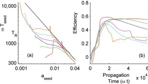
FIG. 3. Investigation of the optimal seed pulse with six one-dimensional PIC simulations. The plasma had zero temperature and constant densityn=ncrit/100, with constant pump amplitude
apump=0.003. The development of six seed pulses, varied in initial
duration at constant energy, is shown with a separate color for each seed pulse. (a) The development of the duration versus the dimensionless peak amplitude of each seed on logarithmic scales. Equation (4) is shown by the black line. The total propagation time was 60 000ω−1for each seed pulse. (b) The energy transfer efficiency
from the pump to the main peak of the seed pulse, as a function of propagation time. Note that the peak efficiency of 0.6 agrees with Fig.2.
the plasma assumed pre-ionized, with zero temperature and uniform density ncrit/100. The simulations used a window moving with the seed pulse, with 120 cells and 960 particles per wavelength. Boundary conditions were free space.
Six simulations, each with a chirped Gaussian seed (fre-quency 0.9ω) of differing initial duration, were propagated forωt=60 000. These parameters were chosen to reflect a new Raman amplification experiment [41] at the Laboratory for Laser Energetics (Rochester, New York, USA) and reside in the high-efficiency region of the parameter space.
The development of the seed pulses in theaseed,Tseedplane is shown in Fig.3(a). The solution (4), shown by the straight black line, accurately describes the later evolution of all seed pulses. Furthermore, its attractive nature is verified by seeds that start away from the line.
There is evidence that the analytic solution is only partially true for seeds longer thanTR, as they initially deviate from the line, before rejoining at around ωTseed=ωTR2000. The pulses longer thanTRexhibited the undesirable characteristic of breaking into several amplified pulses, whereas the shorter seeds gave a much higher power single spike. The evolution of the longer pulses showed dependence on small changes in the initial conditions, suggesting large shot-to-shot variation.
The energy transfer efficiency to the most prominent peak is shown versus propagation time in Fig. 3(b). For some cases, it drops at later stages due to the energy transfer to other competing amplified spikes. By the end, the shortest seed (red) reaches over three times the power and twice the energy than for the longest seed (orange). This is true despite starting further from the attractive solution (4). The self-similar behavior is not observed unlessTseed< TR.
As noted previously [28,42], more intense seeds also work better beyond the wave-breaking threshold. We conclude that short and intense seed pulses are preferable to a much longer
seed that satisfies Eq. (4). The pulse should certainly be shorter thanTR to avoid breaking in to two amplified pulses. These conclusions are for seeds with a fixed fluence and bandwidth. If a seed pulse must ionize the plasma, it would likely need to be compressed to a short durationT < TRfor the requisite ionization intensity, but these results show this is also the condition for best amplifier performance.
Further simulations (not shown) found that changing the shape of the temporal envelope for the seed had little effect compared to changing the duration.
IV. TRANSVERSE COHERENCE
We now investigate adverse effects of the plasma on the transverse coherence of the amplified pulse. A two-dimensional PIC simulation amplified the pulse in a focusing geometry (as originally illustrated in Ref. [6]) and then propagated to its focus in vacuum.
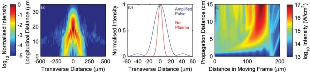
Figures4(a)and4(b)shows the intensity profile at the focus of the amplified pulse, together with the equivalent profile in the control simulation with no plasma. The peak intensity has been normalized to compare the two spot sizes. Parame-ters were chosen to reflect the ongoing experiment at LLE as closely as possible, and they are close to the optimal values found in the previous sections. The simulation box moved with the seed pulse. Its width was 1.3 mm and length was 70μm, with 30 cells per wavelength, cell width 450 nm and 16 electrons per cell. The seed pulse duration of 50 fs is less than the linear Raman growth time of 200 fs, satisfying the conclusions of Fig.3.
This PIC result agrees with the numerical results in references [43,44] in that the amplified pulse largely retains its focusing geometry and coherence. The total energy transfer efficiency from pump to seed was 30%, consistent with Fig.2. This high value is largely due to the powerful initial seed pulse, with power comparable to the pump.
Since the amplified pulse is far above the threshold power for relativistic self-focusing, choice of lower laser intensities reduces the filamentation growth rate and preserves the wavefront fidelity. Analytical estimates confirm this. Energy conservation givesηapump2 t =a2seedTseedfor efficiencyη. Com-bining with Eq. (4) and the filamentation growth rate [45] gives the growth rate γf il=η2a4
pumpωp3t2/200. Integrating
over propagation time gives an estimate of the maximum length of amplifier before the pulse filamentation becomes unbearable:
L
λ =
1 2π
600G
η2a4 pump
1 3
n ncrit
−1 2
, (6)
whereGis the maximum tolerable number of e-foldings. Tak-ingG=5, the maximum length is 1.1 cm for the simulation in Fig.4(a), over double the interaction length. This agrees with the low levels of filamentation seen in the simulation.
FIG. 4. (a, b) A two-dimensional simulation of a primary stage amplifier with finite focal length, demonstrating that the process is possible in a focusing geometry and that transverse coherence is retained. Panel (a) shows the amplified pulse at the time of best focus in vacuum, propagating upwards, whereas panel (b) compares this transverse profile (at the position of peak intensity) with that of the seed pulse focused with no plasma interaction. The plasma profile had the form 1.5×10¹⁹exp[−(x/2 mm)6]/cm3, meaningn/n
crit=0.015, with fixed temperature
400 eV. The seed and pump were Gaussian in space and time, with durations 50 fs and 25 ps, wavelengths 1200 and 1054 nm, both with peak intensity 3×10¹⁴W/cm2in the plasma (a
pump=0.016). Both pulses had transverse width 800μm in the plasma and focus 15 mm beyond the
plasma. (c) Output similar to the first-stage amplifier in (a), albeit at a shorter wavelength, is used to seed a larger secondary stage amplifier using the seed ionization scheme, simulated in one dimension. The simulation used a 10 kJ, 1 ns, 1054 nm pump pulse at 1013W/cm2and a
15 J, 50 fs, 1081 nm seed pulse at 3×10¹⁴W/cm2. The electron density was 6×10¹⁷/cm3(n/n
crit=0.0006) across a 1×1×15 cm region. The
intensity across the space time diagram is shown in a frame moving right, at the group velocity of the amplified pulse.
These results are important for using the technique to focus to frontier level intensities. It also means the output is ideal as a seed for a larger main amplifier stage with a nanosecond pump pulse. The wide bandwidth developed will give some freedom to use a lower electron density for the larger amplifier and still maintain resonance.
Figure 4(c)simulates a hypothetical secondary amplifier stage using the seed ionization scheme. For this main amplifier, the simulations included a field ionization model for hydrogen. It calculates the field ionized fraction at each time step and initializes free electrons accordingly, with a transverse velocity of 0.05c.
The seed and pump had energy 15 J and 10 kJ, respectively. This one-dimensional moving window simulation used 120 cells and 960 electrons per wavelength. At this low density, ionization causes little energy loss, and it quickly enters the high-efficiency nonlinear regime after 3 cm, with a total pump to seed energy transfer of 50%. The pulse envelope remains smooth. The pump will not be adversely affected by the neutral hydrogen gas as the full B integral was estimated at 0.02 [46]. Extrapolated transversely, the output contains 5 kJ in 60 fs. Such a pulse would be invaluable for high field experiments.
Transverse ponderomotive filamentation of the amplified pulse is unlikely to be an issue [47]. Equation (6) gives the maximum length before excessive filamentation as 36 cm, more than double the plasma length. Maintaining wavefront fidelity will necessitate a uniform plasma density. However, for many applications (fast ignition, x-ray generation), exquisite focusing is less important than maximizing the energy of the pulse, as lower intensities are sometimes desirable.
Compression of ultraviolet pulses is also feasible. A seed pulse with wavelength 355 nm could be used with a 351 nm, 10 kJ pump pulse such as those currently available on the National Ignition Facility. Neglecting losses from any collisional damping, the results of Fig.4(c)apply equally to
amplifiers at shorter wavelengths. This is provided that the intensities and the plasma density are scaled proportional to
λ−2. With a critical surface much closer to the dense hydrogen fuel, short ultraviolet pulses will reduce the required energy and open new windows for fast ignition.
In summary, we have performed the first extensive param-eter scan for the optimal performance of plasma amplifiers for compression of large amounts of nanosecond duration energy (>kJ) into subpicosecond pulses. We have conclusively demonstrated that the choice of initial seed greatly influences the ascent into the nonlinear regime, allowing rapid access to high efficiencies. The simulations predict an efficiency for the LLE experiment of 30% with pump ionization or 50% with the seed ionization scheme. Good focusing has been explicitly demonstrated for an output pulse. We have discussed how a two-stage plasma amplifier could represent a step change for generation of high-energy short pulses for high-energy density science.
ACKNOWLEDGMENTS
[image:5.612.55.552.73.190.2][1] J. Craneet al.,J. Phys.: Conf. Ser.244,032003(2010). [2] L. J. Waxeret al.,Opt. Photon. News16,30(2005).
[3] C. Hernandez-Gomezet al.,J. Phys.: Conf. Ser.244,032006 (2010).
[4] B. King, A. Di Piazza, and C. H. Keitel,Phys. Rev. A82,032114 (2010).
[5] H.-P. Schlenvoigtet al.,Nat. Phys.4,130(2008).
[6] V. M. Malkin, G. Shvets, and N. J. Fisch,Phys. Rev. Lett.82, 4448(1999).
[7] M. Tabaket al.,Phys. Plasmas1,1626(1994). [8] D. Strozziet al.,Phys. Plasmas19,072711(2012). [9] R. Trineset al.,Nat. Phys.7,87(2011).
[10] J. P. Farmer and A. Pukhov,Phys. Rev. E88,063104(2013). [11] D. S. Clark and N. J. Fisch,Phys. Plasmas10,3363(2003). [12] V. M. Malkin, G. Shvets, and N. J. Fisch,Phys. Rev. Lett.84,
1208(2000).
[13] R. M. G. M. Trineset al.,arXiv:1611.04485. [14] Y. Pinget al.,Phys. Plasmas16,123113(2009). [15] J. Renet al.,Phys. Plasmas15,056702(2008).
[16] D. Turnbull, S. Li, A. Morozov, and S. Suckewer,Phys. Plasmas 19,083109(2008).
[17] M. Dreher, E. Takahashi, J. Meyer-ter-Vehn, and K.-J. Witte, Phys. Rev. Lett.93,095001(2004).
[18] J. Renet al.,Nat. Phys.3,732(2007).
[19] J. Manley and H. Rowe,Proc. IRE44,904(1956).
[20] N. Yampolsky and N. Fisch,Phys. Plasmas16,072105(2009). [21] T. Wanget al.,Phys. Plasmas17,023109(2010).
[22] R. A. Fonsecaet al.,Lecture Notes on Computer Science 2329, III-342 (Springer-Verlag, Heidelberg, 2002).
[23] E. Cormier-Michel, B. A. Shadwick, C. G. R. Geddes, E. Esarey, C. B. Schroeder, and W. P. Leemans,Phys. Rev. E78,016404 (2008).
[24] A. Bergmann and P. Mulser,Phys. Rev. E47,3585(1993). [25] N. Yampolskyet al.,Phys. Plasmas15,113104(2008). [26] J. P. Farmer, B. Ersfeld, and D. A. Jaroszynski,Phys. Plasmas
17,113301(2010).
[27] M. Edwardset al.,Phys. Plasmas22,074501(2015).
[28] Z. Toroker, V. M. Malkin, and N. J. Fisch,Phys. Plasmas21, 113110(2014).
[29] T. Coffey,Phys. Fluids14,1402(1971).
[30] W. Cheng, Y. Avitzour, Y. Ping, S. Suckewer, N. J. Fisch, M. S. Hur, and J. S. Wurtele,Phys. Rev. Lett.94,045003(2005). [31] Y. Ping, W. Cheng, S. Suckewer, D. S. Clark, and N. J. Fisch,
Phys. Rev. Lett.92,175007(2004).
[32] V. M. Malkin and N. J. Fisch,Eur. Phys. J. Special Topics223, 1157(2014).
[33] Z. Toroker, V. M. Malkin, and N. J. Fisch,Phys. Rev. Lett.109, 085003(2012).
[34] D. S. Clark and N. J. Fisch,Phys. Plasmas10,4848(2003). [35] J. Vieiraet al.,Nat. Commun.7,10371(2016).
[36] D. S. Clark and N. J. Fisch,Phys. Plasmas10,4837(2003). [37] D. S. Clark and N. J. Fisch,Phys. Plasmas9,2772(2002). [38] V. M. Malkin and N. J. Fisch,Phys. Plasmas8,4698(2001). [39] T. M. Antonsen, Jr. and P. Mora, Phys. Rev. Lett.69, 2204
(1992).
[40] W. L. Kruer, The Physics of Laser Plasma Interactions (Addison-Wesley, Reading, MA, 1988).
[41] D. Haberberger, Abstract Book of the ICUIL, Goa, October 2014 (unpublished).
[42] J. P. Farmer and A. Pukhov,Phys. Rev. E92,063109(2015). [43] G. M. Fraiman, N. A. Yampolsky, V. M. Malkin, and N. J. Fisch,
Phys. Plasmas9,3617(2002).
[44] A. A. Solodov, V. M. Malkin, and N. J. Fisch,Phys. Plasmas 10,2540(2003).
[45] C. E. Max, J. Arons, and A. B. Langdon,Phys. Rev. Lett.33, 209(1974).
[46] E. Nibberinget al.,J. Opt. Soc. Am. B14,650(1997). [47] R. M. G. M. Trines, F. Fiúza, R. Bingham, R. A. Fonseca,
L. O. Silva, R. A. Cairns, and P. A. Norreys,Phys. Rev. Lett. 107,105002(2011).