A Notation and System for Expressing and Executing
Cleanly Typed Workflows on Messy Scientific Data
YongZhao1 Jed Dobson2 Ian Foster1,3 Luc Moreau4 Michael Wilde3
1
Department of Computer Science, University of Chicago, Chicago, IL 60637, U.S.A.
2
Department of Psychology, Dartmouth College, Hanover, NH 03755, U.S.A.
3
Mathematics and Computer Science Division, Argonne National Laboratory, Argonne, IL 60439, U.S.A.
4
School of Electronics and Computer Science, University of Southampton, Southampton, U.K.
Abstract
The description, composition, and execution of even logically simple scientific workflows are often complicated by the need to deal with “messy” issues like heterogeneous storage formats and ad-hoc file system structures. We show how these difficulties can be overcome via a typed, compositional workflow notation within which issues of physical representation are cleanly separated from logical typing, and by the implementation of this notation within the context of a powerful runtime system that supports distributed execution. The resulting notation and system are capable both of expressing complex workflows in a simple, compact form, and of enacting those workflows in distributed environments. We apply our technique to cognitive neuroscience workflows that analyze functional MRI image data, and demonstrate significant reductions in code size relative to other approaches.
1
Introduction
When constructing workflows that operate on large and complex datasets, the ability to describe the types of both datasets and workflow components can be invaluable, enabling discovery of datasets and procedures, type checking and composition of procedure calls, and iteration over compound datasets.
Such typing should in principle be straightforward, because of the hierarchical structure of most scientific datasets. For example, in the functional Magnetic Resonance Imaging (fMRI) applications used for illustrative purposes in this paper, we find a hierarchical structure of studies, groups, subjects, experimental runs, and images (see Figure 1). A typical application might build a new study by applying a program to each image in each run for each subject in each group in a study.
Unfortunately, we find that such clean logical structures are typically represented in terms of messy physical constructs (e.g., metadata encoded in directory and file names) employed in ad-hoc ways. For example,
the fMRI physical representation is a nested directory structure, with ultimately a single 3D image (“volume”) represented by two files located in the same directory, distinguished only by file name suffix (Figure 1).
Such messy physical representations make program development, composition, and execution unnecessarily difficult. While we can incorporate knowledge of file system layouts and file formats into application programs and scripts, the resulting code is hard to write and read, cannot easily be adapted to different representations, and is not clearly typed.
Figure 1: fMRI structure, logical (left) & physical (right)
We have previously proposed that these concerns be addressed by separating abstract structure and physical representation [1]. (Woolf et al. [2] have recently proposed similar ideas.) We describe here the design, implementation, and evaluation of a notation that achieve this separation.
We call this notation a virtual data language (VDL) because its declarative structure allows datasets to be defined prior to their generation and without regard to their location and representation. For example, consider a VDL procedure “foo_run” with the signature “Run Y=foo_run(Run X)” and with an implementation that builds and returns a new run Y by applying a program ‘foo’ to each image in the run supplied as argument X (X and Y being dataset variables of type Run). We can
DBIC Archive Study_2004.0521.hgd Group 1
Subject_2004.e024 volume_anat.img volume_anat.hdr bold1_001.img bold1_001.hdr ...
bold1_275.img bold1_275.hdr ...
bold5_001.img ...
snrbold*_* ...air* ... Group 5 ... Study ... DBIC Archive
Study #’2004 0521 hgd’ Group #1
Subject #’2004 e024’ Anatomy
high-res volume Functional Runs run #1 volume #001 ...
volume #275 ...
run #5 volume #001 ...
volume #242 …
Group #5 ... Study #...
then specify via the VDL procedure invocation “run2=foo_run(run1)” that dataset “run2” is to be derived from dataset “run1.” Independence from location and representation is achieved via the use of
XML Dataset Typing and Mapping (XDTM) [3]
mechanisms, which allow the types of datasets and procedures to be defined abstractly, in terms of XML Schema. Separate mappingdescriptors then define how such abstract data structures translate to physical representations. Such descriptors specify, for example, how to access the physical files associated with “run1” and “run2.”
VDL’s declarative and typed structure makes it easy to define increasingly complex procedures via composition. For example, a procedure “Subject Y = foo_subject(Subject X)” might apply the procedure “foo_run” introduced earlier to each run in a supplied subject. The repeated application of such compositional forms can ultimately define large directed acyclic graphs (DAGs) comprising thousands or even millions of calls to “atomic transformations” that each operate on just one or two image files.
The expansion of dataset definitions expressed in VDL into DAGs, and the execution of these DAGs as workflows in uni- or multi-processor environments, is the task of an underlying virtual data system (VDS).
We have applied our techniques to fMRI data analysis problems [4]. We have modeled a variety of dataset types (and their corresponding physical representations) and constructed and executed numerous computational procedures and workflows that operate on those datasets. Quantitative studies of code size suggest that our VDL and VDS facilitate workflow expression, and hence improve productivity.
We summarize the contributions of this paper as follows:
(1) the design of a practical workflow notation and system that separate logical and physical representation to allow for the construction of complex workflows on messy data using cleanly typed computational procedures;
(2) solutions to practical problems that arise when implementing such a notation within the context of a distributed system within which datasets may be persistent or transient, and both replicated and distributed; and
(3) a demonstration and evaluation of the technology via the encoding and execution of large fMRI workflows in a distributed environment.
The rest of the paper is as follows. In Section 2, we review related work. In Section 3, we introduce the XDTM model and in Section 4 we describe VDL, using an fMRI application for illustration. In Section 5 we describe our implementation, and in Section 6 we conclude with an assessment of results and approach.
2
Related Work
The Data Format Description Language (DFDL) [5], like XDTM, uses XML Schema to describe abstract data models that specify data structures independent from their physical representations. DFDL is concerned with describing legacy data files and complex binary formats, while XDTM focuses on describing data that spans files and directories. Thus, the two systems can potentially be used together.
XPDL [6], BPEL, and WSDL also use XML
Schema to describe data or message types, but assume that data is represented in XML; in contrast, XDTM can describe “messy” real-world data by mapping from the logical structure to arbitrary physical representations. Ptolemy [7] and Kepler [8] provide a static typing system; Taverna [9] and Triana [10] do not mandate typing. The ability to map logical types from/to physical representations is not provided by these languages and systems.
When composing programs into workflows, we must often convert logical types and/or physical representations to make data accessible to downstream programs. XPDL employs scripting languages such as JavaScript to select subcomponents of a data type, and BPEL uses XPath expressions in Assign statements for data conversion. Our VDL permits the declarative specification of a rich set of data conversion operations on composite data structures and substructures.
VDL’s focus on DAGs limits the range of programs that can be expressed relative to some other systems. However, we emphasize that workflows similar to those presented here are extremely common in scientific computing, in domains including astronomy, bioinformatics, and geographical information systems. VDL can be extended with conditional constructs (for example) if required, but we have not found such extensions necessary to date.
Many workflow languages allow sequential, parallel, and recursive patterns, but do not directly support iteration. Taverna relies on its workflow engine to run a process multiple times when a collection is passed to a singleton-argument process. Kepler adopts a functional operator ‘map’ to apply a function that operates on singletons to collections. VDL’s typing supports flexible iteration over datasets—and also type checking, composition, and selection.
3
XDTM Overview
in the dataset’s logical schema is stored in, and fetched from, physical structures such as directories, files, and database tables. In order to permit reuse for different datasets, mapping descriptors can refer to external parameters for such things as dataset location(s).
In order to access a dataset, we need to know three things: its type schema, its mapping descriptor, and the value(s) of any external parameter(s). These three components can be grouped to form a dataset handle.
Note that multiple mappings may be defined for the same logical schema (i.e., for a single logical type). For example, an array of numbers might in different contexts be physically represented as a set of relations, a text file, a spreadsheet, or an XML document.
XDTM defines basic constructs for defining and associating physical representations with XML structures. However, it does not speak to how we write programs that operate on XDTM-defined data: a major focus of the work described here.
4
XDTM-Based Virtual Data Language
Our XDTM-based Virtual Data Language (VDL)— derived loosely from an earlier VDL [11], which dealt solely with untyped files—allows users to define procedures that accept, return, and operate on datasets with type, representation, and location defined by XDTM. We introduce the principal features of VDL via an example from fMRI data analysis.
4.1 Application Example
fMRI datasets are derived by scanning the brains of subjects as they perform cognitive or manual tasks. The raw data for a typical study might consist of three subject groups with 20 subjects per group, five experimental runs per subject, and 300 volume images per run, yielding 90,000 volumes and over 60 GB of data. A fully processed and analyzed study dataset can contain over 1.2 million files. In a typical year at the Dartmouth Brain Imaging Center, about 60 researchers preprocess and analyze about 20 concurrent studies.
Experimental subjects are scanned once to obtain a high-resolution image of their brain anatomy (“anatomical volume”), then scanned with a low-resolution imaging modality at rapid intervals to observe the effects of blood flow from the “BOLD” (blood oxygenated level dependant) signal while performing some task (“functional runs”). These images are pre-processed and subjected to intensive analysis that begins with image processing and concludes with a statistical analysis of correlations between stimuli and neural activity.
4.2 VDL Type System
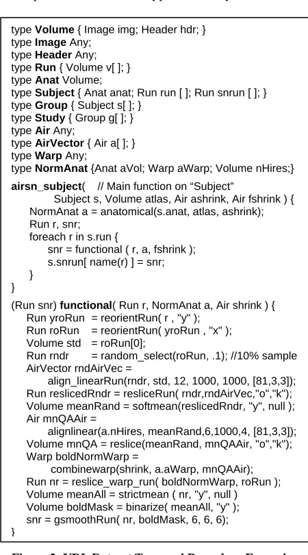
VDL uses a C-like syntax to represent XML Schema types. For example, the first twelve lines of Figure 2
include the VDL types that we use to represent the data objects of Figure 1. (We discuss the procedures later.) Some corresponding XML Schema type definitions are
in Figure 3. A Volume contains a 3D image of a
volumetric slice of a brain image, represented by an Image (voxels) and a Header (scanner metadata). As we do not manipulate the contents of those objects directly within this VDL program, we define their types simply as opaque (Any). A time series of volumes taken from a functional scan of one subject, doing one task, forms a Run. In typical experiments, each Subject has multiple input and normalized runs, and anatomical data, Anat.
Specific output formats involved in processing raw input volumes and runs may include outputs from various image processing tools, such as the automated
image registration (AIR) suite. The type Air
[image:3.612.324.549.260.665.2]corresponds to one dataset type created by these tools.
Figure 2: VDL Dataset Type and Procedure Examples
type Volume { Image img; Header hdr; }
type Image Any;
type Header Any;
type Run { Volume v[ ]; }
type Anat Volume;
type Subject { Anat anat; Run run [ ]; Run snrun [ ]; }
type Group { Subject s[ ]; }
type Study { Group g[ ]; }
type Air Any;
type AirVector { Air a[ ]; }
type Warp Any;
type NormAnat {Anat aVol; Warp aWarp; Volume nHires;}
airsn_subject( // Main function on “Subject”
Subject s, Volume atlas, Air ashrink, Air fshrink ) { NormAnat a = anatomical(s.anat, atlas, ashrink); Run r, snr;
foreach r in s.run {
snr = functional ( r, a, fshrink ); s.snrun[ name(r) ] = snr; }
}
(Run snr) functional( Run r, NormAnat a, Air shrink ) {
Run yroRun = reorientRun( r , "y" ); Run roRun = reorientRun( yroRun , "x" ); Volume std = roRun[0];
Run rndr = random_select(roRun, .1); //10% sample
AirVector rndAirVec =
align_linearRun(rndr, std, 12, 1000, 1000, [81,3,3]); Run reslicedRndr = resliceRun( rndr,rndAirVec,"o","k"); Volume meanRand = softmean(reslicedRndr, "y", null ); Air mnQAAir =
alignlinear(a.nHires, meanRand,6,1000,4, [81,3,3]); Volume mnQA = reslice(meanRand, mnQAAir, "o","k"); Warp boldNormWarp =
4.3 Procedures
Datasets are operated on by procedures, which take data described by XDTM as input, perform computations on those data, and produce data described by XDTM as output. An atomic procedure defines an interface to an executable program or service (more on this below); a compound procedure composes calls to atomic procedures, compound procedures, and/or foreach statements.
A VDL procedure can be viewed as a named
workflow template. It defines a workflow comprising either a single node (atomic procedure) or multiple nodes (compound procedure). It is a template in that its arguments are formal not actual parameters; a call to a VDL procedure instantiates those arguments to define a concrete workflow. Shared variables in the body of a compound procedure specify data dependencies and thus the directed arcs for the DAG corresponding to the compound procedure’s workflow.
Figure 3: Type Definitions in XML Schema
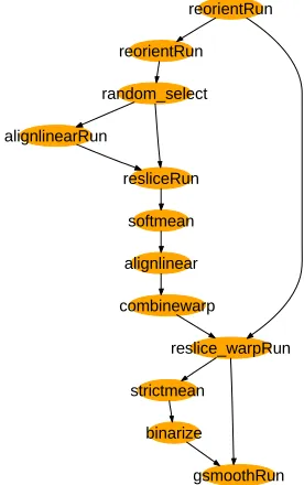
We use as our illustrative example a workflow, AIRSN, that performs spatial normalization for pre-processing raw fMRI data prior to analysis. AIRSN normalizes sets of time series of 3D volumes to a standardized coordinate system and applies motion correction and Gaussian smoothing. Figures 4 and 5 show two views of the most data-intensive segment of the AIRSN workflow, which processes the data from the functional runs of a study. Figure 4 is a high-level representation in which each oval represents an operation performed on an entire Run. Figure 5 expands
the workflow to the Volume level, for a dataset of 10 functional volumes. (The alert reader may note that the random_select call is missing; this is an unimportant artefact.) In realistic fMRI science runs, Runs might include hundreds or thousands of volumes.
reorientRun
reorientRun
reslice_warpRun random_select
alignlinearRun
resliceRun
softmean
alignlinear
combinewarp
strictmean
[image:4.612.367.505.119.339.2]gsmoothRun binarize
Figure 4: AIRSN workflow high-level representation
reorient/01
reorient/02
reslice_warp/22 alignlinear/03 alignlinear/07 alignlinear/11
reorient/05
reorient/06
reslice_warp/23 reorient/09
reorient/10
reslice_warp/24 reorient/25
reorient/51
reslice_warp/26 reorient/27
reorient/52
reslice_warp/28 reorient/29
reorient/53
reslice_warp/30
reorient/31
reorient/54
reslice_warp/32 reorient/33
reorient/55
reslice_warp/34 reorient/35
reorient/56
reslice_warp/36 reorient/37
reorient/57
reslice_warp/38 reslice/04 reslice/08
reslice/12
gsmooth/41 strictmean/39
gsmooth/42 gsmooth/43
gsmooth/44 gsmooth/45 gsmooth/46 gsmooth/47gsmooth/48gsmooth/49 gsmooth/50 softmean/13
alignlinear/17
combinewarp/21
binarize/40 reorient
reorient
alignlinear
reslice
softmean
alignlinear
combine_warp
reslice_warp
strictmean
binarize
[image:4.612.324.540.372.606.2]gsmooth
Figure 5: AIRSN workflow expanded to show all atomic file operations, for a 10 volume run
We present a subset of the VDL for AIRSN in Figure 2. The procedure functional expresses the steps in Figure 4; airsn_subject calls both functional and procedure anatomical (not shown) to process a Subject.
The VDL foreach statement allows programs to apply an operation to all components of a compound <?xml version="1.0" encoding="UTF-8"?>
<xs:schema
targetNamespace="http://www.fmri.org/schema/airsn.xsd" xmlns="http://www.fmri.org/schema/airsn.xsd" xmlns:xs="http://www.w3.org/2001/XMLSchema">
<xs:complexType name="Image"> <xs:complexContent>
<xs:extension base="xs:anyType"/> </xs:complexContent>
</xs:complexType>
<xs:complexType name="Header"> <xs:complexContent>
<xs:extension base="xs:anyType"/> </xs:complexContent>
</xs:complexType>
<xs:complexType name="Volume"> <xs:sequence>
<xs:element name="img" type="Image"/> <xs:element name="hdr" type="Header"/> </xs:sequence>
</xs:complexType>
<xs:complexType name="Run">
data object. For example, airsn_subject creates in the Subject dataset a new spatially normalized Run for each raw Run. Such procedures define how the workflow is expanded as in Figure 5.
To apply a VDL procedure to a specific physical dataset, we simply pass a reference to that dataset as an actual parameter. The resulting call will execute correctly regardless of the physical representation of a passed dataset (assuming that the dataset and procedure have matching logical types). Internally, dataset references take the form of handles, which, as described in Section 3, contain type, mapping, and location information. Handles are never seen by the user.
4.4 Invoking Programs and Services
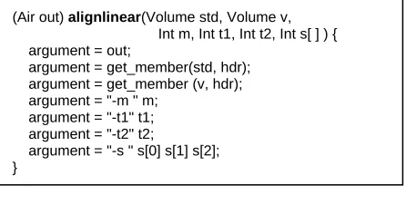
[image:5.612.66.289.341.454.2]A workflow such as Figure 2 must ultimately invoke external executable programs and/or Web Services. VDL atomic procedures define the necessary interfaces, specifying the name of the program or service to be invoked, how to set up its execution environment, how program arguments or service messages should be mapped from and to VDL procedure arguments, and what physical data objects need to be moved to and from remote execution sites.
Figure 6: Program Invocation
For example, the procedure alignlinear called in Figure 2 defines a VDL interface to the AIR utility of the same name. The statements in the body assemble the command to invoke the program, so that for example the VDL call:
Air a = alignlinear(t1a, t3, 12, 1000, 1000, [81 3 3])
requests the execution of the following command:
alignlinear a.air t1a.hdr t3.hdr -m 12 \ -t1 1000 -t2 1000 -s 81 3 3
This command may be executed on a remote computer, in which case the VDS ensures that the physical representations of datasets passed as input arguments are transferred to the remote site, thus ensuring that the executable can access the required physical files. Thus, in the example call, the physical representations of the datasets “t1a” and “t3” are transferred to the remote site.
Similarly, in the case of output data (e.g., “Air a” in the example call), the physical data is left on the remote site, registered in a replica location service, and
optionally copied to another specified site to create an additional replica (which often serves as an archival copy).
Alternative atomic procedure definitions can be provided to specify Web Service interfaces utilities. These alternative procedures would implement the same procedure prototype, but provide a different body.
5
Implementation
We have developed a prototype system that can process VDL type definitions and mappings, convert a typed workflow definition into an executable DAG, expand DAG nodes dynamically to process sub-components of a compound dataset, and submit and execute the resulting DAG in a Grid environment. The separation of dataset type and physical representation that we achieve with VDL can facilitate various runtime optimizations and graph rewriting operations [12].
Our prototype does not yet include a parser for the syntax presented here. However, the prototype does implement the runtime operations needed to support typed VDL dataset processing and execution, which is the principal technical challenge of implementing VDL. We have also verified that we can invoke equivalent services and applications from the same VDL.
The prototype extends an earlier VDS implementation with features to handle data typing and mapping. We use the VDS graph traversal mechanism to generate an abstract DAG in which transformations are not yet tied to specific applications or services, and data objects are not yet bound to specific locations and physical representations. The extended VDS also enhances the DAG representation by introducing “foreach” nodes (in addition to the existing “atomic” nodes) to represent foreach statements in a VDL procedure. These nodes are expanded at runtime (see Section 5.2), thus enabling datasets to have a dynamically determined size.
The abstract DAG is concretized by a Grid planner called Euryale, which produces a concrete DAG that, for each node in the input abstract DAG, performs the following steps. (See Sections 5.1 and 5.2 for details on how Euryale performs data mapping during these steps, and expands foreach statements, respectively.)
1. Preprocess:
if (atomic procedure node) { identify node inputs and outputs;
choose Grid site that meets job requirements; locate and transfer inputs to that site; }
else if (foreach node)
expand foreach statement(s) into sub-dag(s); 2. Execute: Submit job or sub-DAG; wait for it to
execute.
3. Postprocess: Check job exit status; transfer and register outputs; cleanup.
(Air out) alignlinear(Volume std, Volume v,
Int m, Int t1, Int t2, Int s[ ] ) { argument = out;
argument = get_member(std, hdr); argument = get_member (v, hdr); argument = "-m " m;
argument = "-t1" t1; argument = "-t2" t2;
The resulting concrete DAG is executed by the DAGman (“DAG manager”) tool. DAGman provides many necessary facilities for workflow execution, such as logging, job status monitoring, workflow persistence, and recursive fault recovery. DAGman submits jobs to Grid sites via the Globus GRAM protocol.
5.1 Data Mapping
The Euryale planner needs to operate on the physical data that lies behind the logical types defined in VDL procedures. Such operations are accessed via a mapping descriptor associated with the dataset, which controls the execution of a mapping driver used to map between physical and abstract representations. In general, a mapping driver must implement the functions create-dataset, store-member, get-member, and get-member-list. Our prototype employs a table-driven approach to implement a mapping driver for file-system-stored datasets. Each table entry specifies:
name: the data object name
pattern: the pattern used to match file names mode: FILE (find matches in directory)
RLS (find matches via replica location service), ENUM (dataset content is enumerated) content: used in ENUM mode to list content
When mapping an input dataset, this table is consulted, the pattern is used to match a directory or replica location service according to the mode, and the members of the dataset are enumerated in an in-memory structure. This structure is then used to expand foreach statements and to set command-line arguments.
For example, recall from Figure 1 that a Volume is physically represented as an image/header file pair, and a Run as a set of such pairs. Furthermore, multiple Runs may be stored in the same directory, with different Runs distinguished by a prefix and different Volumes by a suffix. To map this representation to the logical Run structure, the pattern ‘boldN*’ is used to identify all pairs in Run N at a specified location. Thus, the mapper, when applied to the following eight files, identifies two runs, one with three Volumes (Run 1) and the otherwith one (Run 2).
bold1_001.img bold1_001.hdr bold1_002.img bold1_002.hdr bold1_003.img bold1_003.hdr bold2_007.img bold2_007.hdr
5.2 Dynamic Node Expansion
A node containing a foreach statement must be
expanded prior to execution into a set of nodes: one per component of the compound data object specified in the foreach. This expansion is performed at runtime: when a foreach node is scheduled for execution, the appropriate mapper function is called on the specified dataset to determine its members, and for each member of the dataset identified (e.g., for each Volume in a Run) a new job is created in a “sub-DAG.”
The new sub-DAG is submitted for execution, and the main job waits for the sub-DAG to finish before proceeding. A post-script for the main job takes care of the transfer and registration of all output files, and the collection of those files into the output dataset. This workflow expansion process may itself recurse further if the subcomponents themselves also include foreach statements. DAGman provides workflow persistence even in the face of system failures during recursion.
5.3 Optimizations and Graph Transformation
Since dataset mapping and node expansion are carried out at run time, we can use graph transformations to apply optimization strategies. For example, in the AIRSN workflow, some processes, such as the reorient of a single Volume, only take a few seconds to run. It is inefficient to schedule a distinct process for each Volume in a Run. Rather, we can combine multiple such processes to run as a single job, thus reducing scheduling and queuing overhead.
As a second example, the softmean procedure
computes the mean of all Volumes in a Run. For a dataset with large number of Volumes, this stage is a bottleneck as no parallelism is engaged. There is also a practical issue: the executable takes all Volume filenames as command line arguments, which can exceed limits defined by the Condor and UNIX shell tools used within our VDS implementation. Thus, we transform this node into a tree in which leaf nodes compute over subsets of the dataset. The process repeats until we get a single output. The shape of this tree can be tuned according to available computing nodes and dataset sizes to achieve optimal parallelism and avoid command-line length limitations.
6
Evaluation
We have used our prototype system to execute a range of fMRI workflows with various input datasets on the Dartmouth Green Grid, which comprises five 12-node clusters. The dataset mapping mechanism allowed us to switch input datasets (e.g., from a Run of 80 volumes to another Run of 120 volumes) without changing either the workflow definition or the execution system. All workflows run correctly and achieve speedup.
The primary focus of our work is to increase productivity [13]. As an approximate measure of this, we compare in Table 1 the lines of code needed to express five different fMRI workflows, coded in our new VDL, with two other approaches, one based on ad-hoc shell scripts (“Script,” able to execute only on a single computer) and a second (“Generator”) that uses Perl scripts to generate older, “pre-XDTM” VDL.
Table 1: Lines of code with different workflow encodings
Workflow Script Generator VDL
GENATLAS1 49 72 6
GENATLAS2 97 135 10
FILM1 63 134 17
FEAT 84 191 13
AIRSN 215 ~400 37
7
Conclusions
We have designed a typed workflow notation and system that allows workflows to be expressed in terms of declarative procedures that operate on XML data
types and then executed on diverse physical
representations and on distributed computers. We show that this notation and system can be used to express large amounts of distributed computation easily.
The productivity leverage of this approach is apparent: a small group of developers can define VDL interfaces to the utility packages used in a research domain and then create a library of dataset-iteration functions. This library encapsulates low-level details concerning how data is grouped, transported, catalogued, passed to applications, and collected as results. Other scientists can then use this library to construct workflows without needing to understand details of physical representation, and furthermore are protected by the XDTM type system from forming workflows that are not type compliant. In addition, the data management conventions of a research group can be encoded in XDTM mapping functions, thus making it easier to maintain order in dataset collections that may include tens of millions of files.
We next plan to automate the parsing steps that were performed manually in our prototype, and to create a complete workflow development and execution environment for our XDTM-based VDL. We will also investigate support for services, automation of type coercions between differing physical representations, and recording of provenance for large data collections.
Acknowledgements.
This work was supported by the National Science Foundation GriPhyN Project, grant ITR-800864, the Mathematical, Information, and Computational Sciences Division subprogram of the Office of Advanced Scientific Computing Research, U.S. Department of Energy, and by the National Institutes of Health, grants NS37470 and NS44393. We are grateful to Scott Grafton of the Dartmouth Brain Imaging Center, and to Jens Voeckler, Doug Scheftner, Ewa Deelman, Carl Kesselman, and the entire Virtual Data System team for discussion, guidance, and assistance.
References
[1] Foster, I., Voeckler, J., Wilde, M., Zhao, Y. The Virtual Data Grid: A New Model and Architecture for Data-intensive Collaboration. Conference on Innovative Data Systems Research, Asilomar, CA, January 2003. [2] Woolf, A., Cramer, R., Gutierrez, M., van Dam, K.,
Kondapalli, S., Latham, S., Lawrence, B., Lowry, R., O'Neill, K., Semantic Integration of File-based Data for Grid Services. Workshop on Semantic Infrastructure for Grid Computing Applications, 2005.
[3] Moreau, L., Zhao, Y., Foster, I., Voeckler, J. Wilde, M., XDTM: XML Dataset Typing and Mapping for Specifying Datasets. European Grid Conference, 2005. [4] Van Horn, J.D., Dobson, J., Woodward, J., Wilde, M.,
Zhao, Y., Voeckler, J., Foster, I. Grid-Based Computing and the Future of Neuroscience Computation, Methods in Mind, Cambridge: MIT Press (In Press).
[5] Beckerle, M., Westhead, M. GGF DFDL Primer. Technical report, Global Grid Forum, 2004.
[6] XML Process Definition Language (XPDL) (WFMCTC-1025). Technical report, Workflow Management Coalition, Lighthouse Point, Florida, USA, 2002. [7] Eker, J., Janneck, J., Lee, E., Liu, J., Liu, X., Ludvig, J.,
Neuendorffer, S., Sachs, S., Xiong, Y. Taming Heterogeneity – the Ptolemy Approach. Proceedings of the IEEE, 91(1):127-144, January 2003.
[8] Altintas, I., Berkley, C., Jaeger, E., Jones, M., Ludäscher, B. and Mock, S., Kepler: An Extensible System for Design and Execution of Scientific Workflows. 16th Intl. Conference on Scientific and Statistical Database Management, 2004.
[9] Oinn, T., Addis, M., Ferris, J., Marvin, D., Senger, M., Greenwood, M., Carver, T., Glover, K., Pocock, M., Wipat, A., Li, P. Taverna: A Tool for the Composition and Enactment of Bioinformatics Workflows.
Bioinformatics Journal, 20(17):3045-3054, 2004. [10]Churches, D., Gombas, G., Harrison, A., Maassen, J.,
Robinson, C., Shields, M., Taylor, I. Wang, I.
Programming Scientific and Distributed Workflow with Triana Services. Concurrency and Computation: Practice and Experience, 2005 (in press).
[11]Foster, I., Voeckler, J., Wilde, M., Zhao, Y. Chimera: A Virtual Data System for Representing, Querying and Automating Data Derivation. 14th Conference on Scientific and Statistical Database Management, 2002. [12]Deelman, E., Blythe, J., Gil, Y., Kesselman, C., Mehta, G., Vahi, K., Blackburn, K., Lazzarini, A., Arbree, A., Cavanaugh, R., Koranda, S. Mapping Abstract Workflows onto Grid Environments. Journal of Grid Computing, 1(1). 2003.