i UNIVERSITI TEKNIKAL MALAYSIA MELAKA
SODIUM ALGINATE CONCENTRATION DERECTION USING FIBER OPTIC COMPONENT AS SENSOR ELEMENT
This report submitted in accordance with requirement of the Universiti Teknikal Malaysia Melaka (UTeM) for the Bachelor Degree of Electronic Engineering
Technology (Telecommunications) with Honours
By
SHIRLEY LORITA ANAK LOUIS B071310500
930505-13-6538
ii TAJUK: Sodium Alginate Concentration Detection Using Fiber Optic as Sensor Element SESI PENGAJIAN: 2016/2017 Semester 1
Saya SHIRLEY LORITA ANAK LOUIS
Mengaku membenarkan Laporan PSM ini disimpan di Perpustakaan Universiti Teknikal Malaysia Melaka (UTeM) dengan syarat-syarat kegunaan seperti berikut:
1. Lapaoran PSM adalah hak milik Universiti Teknikal Malaysia Melaka dan penulis. 2. Perpustakaan Universiti Teknikal Malaysia Melaka dibenarkan membuat Salinan
untuk tujuan pengajian sahaja dengan izin penulis.
3. Perpustakaan dibenarkan membuat Salinan laporan PSM ini sebagai bahan pertukaran antara instituisi pengajian tinggi.
4. ***Sila tandakan (√)
SULIT
TERHAD
TIDAK TERHAD
Disahkan oleh:
shirleyloritalouis ______________________
Alamat Tetap: Cop Rasmi:
Lot 201, Bukit Penyau, Jalan Salim, 96000 Sibu, Sarawak.
Tarikh:____________________ Tarikh:_________________
** Jika Laporan PSM ini SULIT atau TERHAD, sila lampirkan surat daripada pihak berkuasa/organisasi berkenaan dengan menyatakan sekali sebab dan tempoh laporan PSM ini perlu dikelaskan sebagai SULIT atau TERHAD.
(Mengandungi maklumat yang berdarjah keselamatan atau kepentingan Malaysia sebagaimana yang termaktub dalam AKTA RAHSIA RASMI 1972)
(Mengandungi maklumat TERHAD yang telah ditentukan oleh organisasi/badan di mana penyelidikan dijalankan)
√
BORANG PENGESAHAN STATUS LAPORAN PROJEK SARJANA MUDA
ii DECLARATION
I hereby, declared this report entitled “Sodium Alginate Concentration Detection Using Fiber Optic Component as Sensor Element” is the results of my own research except as
cited in references.
Signature : ……….
Author’s Name : SHIRLEY LORITA ANAK LOUIS
iii APPROVAL
This report is submitted to the Faculty of Engineering of UTeM as a partial fulfillment of the requirements for the degree of Bachelor of Electronic Engineering Technology (Telecommunications) with Honours. The member of the supervisory is as follow:
………
iv ABSTRAK
v ABSTRACT
vi DEDICATION
Every challenging work needs self-efforts as guidance of elders especially those who were very close to our heart.
My humble effort I dedicate to my only sweet and loving
Father and Mother,
Louis anak Muli
Margaret anak Benar
Whose affection, love and encouragement and prays of day and night make me able to get such success and honor,
Along with all hard working and respected Supervisor
vii ACKNOWLEDGEMENT
Firstly, I would like to thank God for being able to complete this report on time and successfully.
Next, I would like to put on record and warmly expressed my gratitude to my precious mentor which is also my supervisor Mr. Md. Ashadi bin Md. Johari for the continuous encouragement and inspired motivation. Thank you to my invaluable supervisor, for lending me your hands when I need a guidance throughout in completing this report.
viii TABLE OF CONTENT
Declaration ii
Approval iii
Abstrak iv
Abstract v
Dedication vi
Acknowledgement vii
Table of Contents viii-x
List of Tables xi-xiii
List of Figures xiv-xvi
CHAPTER 1: INTRODUCTION
1.1 Project Background 1
1.2 Objective 3
1.3 Problem Statement 4
1.4 Scope Project 4
CHAPTER 2: LITERATURE REVIEW
2.1 Fiber Optic 5
2.1.1 Basic Structure of an Optical Fiber 5
2.1.2 Propagation Modes of Fiber Optic 9
ix
2.2 Fiber Optic Sensor 13
2.2.1 Basic Principles of Fiber Optic Sensor 13
2.2.2 Classifications of Fiber Optic Sensor 14
2.2.3 Advantages of Optical Fiber Sensors 16
2.2.4 Fields of Application 18
2.2.5 Issues Regarding Fiber Optic Sensor 19
2.3 Sodium Alginate 20
2.3.1 Background of Sodium Alginate 20
2.3.2 Benefits of Sodium Alginates in Health 21
2.3.3 Future Research of Sodium Alginate 23
2.4 New Technology in Fiber Optic Sensor 23
CHAPTER 3: METHOLOGY
3.0 Introduction 25
3.1 Discussion with Supervisor 25
3.2 Process of Cutting 25
3.3. Process of Stripping 26
3.4 Process of Cleaving 26
3.5 Process of Splicing 27
3.6 Experiment on Various Concentration of Sodium Alginate 28
3.7 The Flowchart for the Process of Experiment 30
x CHAPTER 4: RESULT & DISCUSSION
4.1 Introduction 33
4.2 Analysis of 20% Concentration of Sodium Alginate 34
4.3 Analysis of 40% Concentration of Sodium Alginate 40
4.4 Analysis of 60% Concentration of Sodium Alginate 45
4.5 Analysis of 80% Concentration of Sodium Alginate 50
4.6 Analysis of 100% Concentration of Sodium Alginate 55
4.7 Summary for the Best Performance in Fiber Optic Sensors with Various
Concentration of Sodium Alginate 60
CHAPTER 5: CONCLUSION
5.1 Introduction 61
5.2 Conclusion on Chapter 1 and Chapter 2 61
5.3 Conclusion on Chapter 3 62
5.4 Conclusion on Chapter 4 62
5.5 Future Research Recommendation 63
REFERENCES 64-66
APPENDICES 67
xi LIST OF TABLES
Table Title Page
4.1 Regression Analysis for 20% Concentration of Sodium Alginate
Using 850 nm Light Source 35
4.2 Regression Analysis for 20% Concentration of Sodium Alginate
Using 1300 nm Light Source 36
4.3 Regression Analysis for 20% Concentration of Sodium Alginate
Using 1310 nm Light Source 37
4.4 Regression Analysis for 20% Concentration of Sodium Alginate
Using 1550 nm Light Source 38
4.5 Comparison Between 20% Concentration of Sodium Alginate
with Different Light Source 39
4.6 Regression Analysis for 40% Concentration of Sodium Alginate
Using 850 nm Light Source 41
4.7 Regression Analysis for 40% Concentration of Sodium Alginate
Using 1300 nm Light Source 42
4.8 Regression Analysis for 40% Concentration of Sodium Alginate
Using 1300 nm Light Source 43
4.9 Regression Analysis for 40% Concentration of Sodium Alginate
Using 1550 nm Light Source 43
4.10 Comparison Between 40% Concentration of Sodium Alginate
with Different Light Source 44
4.11 Regression Analysis for 60% Concentration of Sodium Alginate
Using 850 nm Light Source 46
4.12 Regression Analysis for 60% Concentration of Sodium Alginate
xii 4.13 Regression Analysis for 60% Concentration of Sodium Alginate
Using 1310 nm Light Source 48
4.14 Regression Analysis for 60% Concentration of Sodium Alginate
Using 1550 nm Light Source 48
4.15 Comparison Between 60% Concentration of Sodium Alginate
with Different Light Source 49
4.16 Regression Analysis for 80% Concentration of Sodium Alginate
Using 850 nm Light Source 51
4 17 Regression Analysis for 80% Concentration of Sodium Alginate
Using 1300 nm Light Source 52
4.18 Regression Analysis for 80% Concentration of Sodium Alginate
Using 1310 nm Light Source 52
4.19 Regression Analysis for 80% Concentration of Sodium Alginate
Using 1550 nm Light Source 53
4.20 Comparison Between 60% Concentration of Sodium Alginate
with Different Light Source 54
4.21 Regression Analysis for 100% Concentration of Sodium Alginate
Using 850 nm Light Source 56
4.22 Regression Analysis for 100% Concentration of Sodium Alginate
Using 1300 nm Light Source 57
4.23 Regression Analysis for 100% Concentration of Sodium Alginate
Using 1310 nm Light Source 58
4.24 Regression Analysis for 100% Concentration of Sodium Alginate
Using 1550 nm Light Source 58
4.25 Comparison Between 60% Concentration of Sodium Alginate
with Different Light Source 59
4.26 The Comparison for the Best Performance of Fiber Optic Sensor Between Various
xiii LIST OF FIGURES
CHAPTER 2: LITERATURE REVIEW
Figure Title Page
1.1 Figure of Cylindrical Optical Fiber 7
2.2 Basic Structure of an Optical Fiber 7
2.3 Basic Structure of the Loose Buffer and Tight Buffer 9
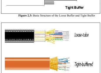
2.4 Loose Buffer Cable and Tight Buffer Cable 9
2.5 The Transmission Modes of Optical Fiber 10
2.6 Different Types of Fibers 11
2.7 Total Internal Reflection of Material 13
2.8 The Equation of the Snell Law’s 13
2.9 Optical Fiber Transmission 14
2.10 Basic Components of Fiber Optic Sensor System 15
2.11 Extrinsic and Intrinsic Types of Fiber Optic Sensors 16
xiv CHAPTER 3: METHODOLOGY
Figure Title Page
3.1 The Miller Stripper Used to Strip the Fiber Optic 26
and Pigtails Cable
3.2 The Process of Stripping the Outer Protective Layer On the Fiber
Optic Cable and pigtails Cable 27
3.3 The Process of Cleaving the Fiber Optic Cable and Pigtails Cable 27
3.4 The Process of Cleaning the Stripped Parts of Fiber Optic
and Pigtails 27
3.5 The Process of Clamping Fiber Optic Ends and Pigtails On Splicer 28
3.6 The Process of Joining Fiber Optic and Pigtails by Fusion Splicing 28
3.7 The Setup Experiment for Testing the Various Concentration of
Sodium Alginate Using Fiber Optic as Sensor Element 29
3.8 The Flowchart for the Process of Experiment 31
CHAPTER 4: RESULT AND DISCUSSION
Figure Title Page
4.1 Graph of Output Power versus Time for 20% Concentration of
Sodium Alginate using Different Light Source 33
4.2 Graph of Output Power versus Time for 40% Concentration of
Sodium Alginate using Different Light Source 38
4.3 Graph of Output Power versus Time for 60% Concentration of
xv 4.4 Graph of Output Power versus Time for 80% Concentration of
Sodium Alginate using Different Light Source 48
4.5 Graph of Output Power versus Time for 100% Concentration of
1 CHAPTER 1
INTRODUCTION
1.0 INTRODUCTION
In this chapter, the topics covered are the background of the project title, project’s objectives, problem statements faced, work scopes, project significant and lastly conclusion of this project.
1.1 PROJECT BACKGROUND
2 (Kist & Sohler, 1983) defines that a Fiber-Optic sensor (FOS) consists essentially of a light source, a fiber link and connectors, a detector, and a sensor element. This sensor element might be localized or distributed and is exposed to the light modulating action of the measured or parameter of interest.
From the article under title Fundamentals of Optical Fiber Sensors (Zujie Fang, 2012) stated that optical fiber sensor technology has grown into a large-scale industry, with its research and development becoming a trending field. Optical fiber sensor has found varied applications in human social activities and daily living, from industrial production to cultural activities, from civil engineering to transportation, from medicine and health care to scientific research, and from residence security to national defense.
According to the article under title Fiber Optic Essentials (Thyagarajan & Ghatak, 2007) stated that although the most important application of optical fibers is in the field of communication, optical fibers are finding more and more applications in the area of sensing. The use of optical fibers for such applications offers the same advantages as in the field of communication: lower cost, smaller size, rugged, higher accuracy, greater flexibility with multifunctional capabilities, wide range of sensor gauge lengths, and greater reliability. Compared to the conventional electrical sensors, such fiber optic sensors are immune to the external electromagnetic interference and can also be used in hazardous and explosive environments. Using fiber optic sensors, it is possible to measure almost any external parameter, such as pressure, temperature, electric current, magnetic field, rotation, acceleration, strain, and chemical and biological parameters, with greater precision and speed. These advantages lead to increased integration of such fiber optic sensors into such civil structures as bridges and tunnels, process industries, medical instruments, aircrafts, missiles, and even cars.
3 the need of warmth within the sight of calcium. Sodium Alginate is the main non-surgical treatment that can physically forestall reflux sickness regardless whether it is acidic or not. Alginates works quickly, are enduring, economical, and it is known not no symptoms.
According to the article under the title Medical Botany: Plants Affecting Human Health (Walter H. Lewis, 2003) stated that in modernist cuisine, sodium alginate is mostly used with calcium salts to produce small caviar-like and large spheres with liquid inside that burst in the mouth. Sodium Alginate is also used in the food industry to increase viscosity and as an emulsifier. It is also used in indigestion tablets and it has no discernible flavor. Alginates have long been used for treating heartburn and significantly reducing gastrointestinal acid reflux episodes.
This project is focusing on how Sodium Alginate concentration detection by using Fiber Optic component as sensor element. This project would greatly contribute to biomedical researcher to use an accurate percentage of this chemical for health purpose. As more and more fiber optic sensing systems are installed and as increasing numbers of engineers from different industrial areas become acquainted with this technology, it will most certainly experience increasing commercial success (Thevenaz, 2011).
1.2 OBJECTIVE
The main objectives of this project:
1. To study and understand the usage of fiber optic sensor.
2. To develop fiber optic sensor for Sodium Alginate in various concentration.
4 1.3 PROBLEM STATEMENT
It is proven by biomedical researcher that sodium alginate helps to reduce the health problems related to the stomach. Heartburn or acid reflux is an obnoxious condition which can be to a great degree excruciating that some individuals depict the sensation as feeling like they are encountering a heart attack. Hydrochloric corrosive is actually present in the stomach that processes the nourishment and eliminate microscopic organisms. The stomach should be acidic and this helps it separate sustenance and gives some resistance against microscopic organisms and infections and it is just when this corrosive getaway from the stomach into the throat that it might prompt issues. Consuming sodium alginate in various concentration levels help to reduce the stomach pain and in order to neutralize the acid in the stomach, the appropriate amount of sodium alginate should be taken. So throughout this project, fiber optic sensor is used to determine the appropriate concentration level of sodium alginate and detect the most active sodium alginate within various concentrations. This project would help biomedical researcher to use an accurate percentage of this chemical for health purpose.
1.4 SCOPE PROJECT
5 CHAPTER 2
LITERATURE REVIEW
2.0 INTRODUCTION
The characteristics and some information of the devices being used in the project are discussed in this chapter. The research topics that had been discussed in this chapter are basic structure of an optical fiber, fiber optic sensor, sodium alginate and new technology in fiber optic.
2.1 FIBER OPTIC
2.1.1 Basic Structure of an Optical Fiber
6 interface changes depending on the incidence angle and the refraction indexes of the core and the cladding. Figure 1 presents the idea of the light propagation in the cylindrical optical fiber due to the total internal reflection.
Figure 2.1: Figure of Cylindrical Optical Fiber
According to (Rongqing Hui, 2009) Optical fiber is the most important component in fiber optic communication systems as well as in many fibers based optical measurement setups. The basic structure of an optical fiber is shown in Figure 2 which has a central core, cladding, and an external coating to protect and strengthen the fiber.
Figure 2.2: Basic Structure of an Optical Fiber
The core is a round and hollow bar of dielectric material. Dielectric material leads no power. Light propagates mainly along the core of the fiber. The core is generally made of glass. The core is surrounded by a layer of material called the cladding. Despite the fact that light will propagates along the fiber center without the layer of cladding material, the cladding does perform some vital capacities.
The cladding layer is made of a dielectric material with an index of refraction n2.
[image:22.612.162.492.385.533.2]7 cladding is generally made of glass or plastic. The cladding performs the following functions:
1. Reduces loss of light from the core into the surrounding air 2. Reduces scattering loss at the surface of the core
3. Protects the fiber from absorbing surface contaminants 4. Adds mechanical strength
For additional assurance, the cladding is encased in an extra layer called the coating or buffer. The covering or support is a layer of material used to shield an optical fiber from physical harm. The material utilized for a buffer is a kind of plastic. The buffer layer (once in a while called the coating) has nothing to do with light transmission and is utilized just for mechanical strength and protection.
8 Figure 2.3: Basic Structure of the Loose Buffer and Tight Buffer
[image:24.612.152.496.219.469.2]