IMPROVING PROCESS STABILITY IN STAMPING OPERATIONS
THROUGH DESIGN OF EXPERIMENTS METHODS
by
Richard Taube
B. Eng. University of Melbourne (1990)
A thesis submitted for the degree o f Master o f Engineering
o f the Australian National University
Department of Engineering, FEIT The Australian National University
Canberra, ACT Australia
DECLARATION
This thesis contains no material which has been previously accepted for the award of any
other degree or diploma in any university, institute or college, and to the best of my
knowledge and belief, contains no material previously published or written by another
ABSTRACT
Sheet Metal Forming particularly in the area of Stamping has been and continues
to be a challenge to the field of Science & Engineering. The reason for this is the
complexity of Stamping Operations owing to the inherently large number of variables
inherent in the Stamping process.
The focus of this thesis was to generate a better understanding of sheet metal
stamping by analysing the variables affecting the process using FE analysis and Design of
Experiments. This enables one to determine which process variables (or parameters)
actually influence the stamping process and by how much.
In addition to this, the important parameters were controlled in order to achieve
process stability and repeatability by optimising their settings. The developed
understanding has enabled production staff to operate the stamping process more
efficiently and effectively using a methodical approach to production problem analysis
rather than the classical haphazard approach.
ACKNOWLEDGMENTS
This work was supported by a grant from the Ford Motor Company of Australia
and the author wishes to thank the company for permission to present this report. The
author also wishes to thank Dr.M.J. Cardew-Hall for his guidance and advice throughout
CONTENTS
C hapterl. Introduction... 10
1.1 General Background... 10
1.2 Aims and Objectives... 11
1.3 Scope... 11
1.4 Background...13
1.5 Introduction to Press Shop operations... 15
1.6 The Artisan W ay... 21
1.7 Alternative Approach...24
Chapter2. Theory of Deep Drawing...27
2.1 Introduction... 27
2.1.1 Stress, Strain & the Simple Tensile Test...27
2.2 Plasticity...30
2.2.1 Yield Phenomena...30
2.2.2 Yield Criteria...31
2.2.3 Work Hardening Index... 35
2.2.4 Anisotropy... 36
2.3 Friction...39
2.3.1 Basic Concepts...39
2.3.2 Variables Affecting Friction...39
2.3.3 Role of Lubricants... 40
2.4 Limiting Draw Ratio... 41
Chapter3. Preview of Current Areas of Research... 43
3.1 FE Analysis... 43
3.2 Circle Grid Analysis... 44
3.3 Analytical Modelling... 46
3.4 Experimental Approaches...47
Chapter4. Process V ariables... 49
4.1 Introduction... 49
< 4.2 Input Variables... 50
4.3 Static Variables... 56
4.4 Output Variables... 57
Chapters. Measuring the Variables... 63
5.1 Introduction... 63
5.2 Measuring Shut Height... 63
5.3 Measuring Lubrication... 64
5.4 Measuring Blank Position in D ie... 65
5.5 Measuring Comer Pressures...65
5.6 Measuring Flange Lengths...65
5.7 Measuring Thickness Strain at the worst location... 65
Chapterö. DoE Methodologies Employed... 69
6.1 Factorial Experimentation Method... 69
6.1.1 Classical Methods...69
6.1.2 Analysis of Variance...70
6.1.3 Two Factor Experiments... 73
6.1.4 Three Factor Experiments... 76
6.2 Yates Algorithm... 80
Chapter7. 2 Level Factorial Experiments... 82
7.1 Introduction... 82
7.2 Variables... 82
7.3 Experimental Procedure...83
7.4 Summary of Results...85
7.5 Summary of Analysis...87
7.6 Conclusions... 90
Chapter8. 3 Level Factorial Experiments... 92
8.1 Introduction... 92
8.2 Variables... 93
8.3 Experimental Procedure... 94
8.4 Summary of Results... 95
8.5 Summary of Analysis... 96
8.6 Conclusions...98
Chapter9. Corner Pressure Factorial Experim ents... 99
9.1 Introduction...99
9.2 Variables...99
9.3 Experimental Procedure... 100
9.4 Summary of Results... 101
9.5 Summary of Analysis... 102
9.6 Conclusions... 102
ChapterlO. The Way F orw ard...104
10.1 Introduction... 104
10.2 Optimisation of Response Surfaces... 104
10.3 Feedback control of Binder Pressure... 104
10.4 In Die Sensing... 106
10.5 FE modelling using commercial packages... 106
10.6 Tonnage measurement...108
10.7 Blankholder Gap measurement... 113
10.8 Flexible Tooling...114
10.9 Improving processing time and Computer Modelling... 117
10.10 Modelling Friction...119
10.11 Research of Sheet Metal Production... 120
122 Chapter 11. Overall Conclusions...
Appendixl. 2 Level Factorial Experimental Results
Appendix2. 2 Level Factorial Experimental ANOVA Results
Appendix3. 2 Level Factorial Experimental Graphical Results
Appendix4. 3 Level Factorial Experimental Results
AppendixS. 3 Level Factorial Experimental ANOVA Results
Appendix6. 3 Level Factorial Experimental Graphical Results
Appendix7. Minimum Draw-in Data
Appendix8. Corner Pressure Factorial Experimental YATES Results
Definitions
m
Q
NOMENCLATURE
Ge - Engineering Stress P = Applied Load
A0 = Original Cross Sectional Area s = Engineering Strain
/ = length
l0 = original length ,= Yield Stress
= Youngs Modulus
gu = Ultimate Tensile Stress cti, g2, g3 = Principal Stresses imax = Maximum Shear Stress k = Shear Yield Stress
a, = True Stress
Aj = Instantaneous Cross-Sectional Area 8, = True Strain
n = Work Hardening Index rw = Anisotropy
Ar = Planar Anisotropy rm = Normal Anisotropy Fr = Frictional Force p = Co-efficient of Friction Fn = Normal Reaction Force (j. = Population Mean
N = Sample Population g = Population Variance SS = Sum of Squares DF = Degrees of Freedom
T = Grand Total of all observations N = Total Number of Observations Tc = Total for each Column
SScr = Column Row Interaction
CHAPTER 1
INTRODUCTION
1.1 General Background
This project was unlike most Master of Engineering projects in that it was
conceived at the outset as "Industry Based". This meant that the student would be
required to spend a considerable period of his/her time in a shop floor environment in
order to gain a fuller understanding of the sheet metal forming process (stamping), how it
operates, what it involves and what it is influenced by. Thus the project was to have a
rather strong industrial focus not only so that the student would be more effective due to
his/her understanding, but also in order that a real problem could be solved.
This approach is not common in Master of Engineering degree Projects. The
format was pursued in order to fill a perceived gap existing between research theory and
practice. Whilst many of the traditional lines of research in sheet metal forming have
raised the overall body of knowledge in the fundamentals of stamping operations, very
little of this type of information nor approach is used by shop floor staff. The overall
drive of the project was to improve the repeatability of the drawing operation of the
stamping process. It is quite common, for example, to have a method of setting up the
draw press at the beginning of a production run based on the ideas and opinions of one, or
more, stamping personnel which in turn are based on hearsay or previous experience.
This particular method may work some of the time. Yet, quite often, the method does not
drawing process producing a part satisfactorily during a production run, suddenly
becomes unstable and no longer produces a satisfactory part. Once again, there is no
feasible explanation and attempts to rectify the problem may even make it worse since
the methods used to attempt a fix are haphazard and based on personal experience. Hence
the desire to introduce a level of repeatability in the process based on real process data
which has been scientifically recorded.
1.2 Aims and Objectives
The specific aims of this project were:
- To develop an understanding of the process physics in the context of the Ford
stamping line at Geelong.
- Derive a suitable model of the stamping line in a format suitable for process
engineers to carry out DoE simulations.
- Use scientific methods to make actual improvements in press shop operations
rather than the traditional "rules of thumb".
- Improve the relationship between industry and academia in order to make
"industry based" projects ongoing to the benefit of both parties.
1.3 Scope
The Stamping Process is very complex and there were many avenues of
investigation in which our efforts may have been channelled. Initially, it was thought
appropriate to explore the following areas:
- Design of Experiments encompassing all the variables of the stamping process.
- Finite Element modelling of the process.
- Characteristics of friction within stamping, particularly deep drawing.
- Instrumentation of the machinery in order to facilitate accurate measurement and
recording of Process variable data.
- Investigation of the manufacture of steel and its role in the stamping process.
Due to time and system constraints, it was not possible to incorporate all of these
points into the project. Thus, the focus of the project became how an improved
understanding of the process could be gained by DoE methods and how this knowledge
could be used to optimise the process.
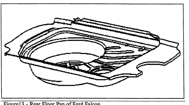
It was decided to focus on a particular part which was not overly complex in a
geometrical sense yet presented enough difficulties during setup and production to
warrant significant effort in terms of scientific research. The part chosen was known as
the Rear Floor Pan and was a structurally significant part of the chassis of the then
current model Ford Falcon Sedan. Typical problems experienced prior to research
included large splits in the drawn form of the part. A split is the extreme case of
stretching. It is the result of the sheet metal being worked beyond the plastic range and
failing. Wrinkling in some areas was also a problem however not to the extent of the
above mentioned problems. A wrinkle is the buckling of the sheet metal brought about by
compressive stresses which may be induced by any number of combination of forces
acting within a die set. The other area of concern was excess drawing occurring in certain
locations providing insufficient material for spot welding later on in manufacture in a
condition known as “short flanges”.
A second project was run in parallel with this project which involved the
were carried out using this model and comparisons made with the actual part produced in
the Stamping Plant.
1.4 Background
Stamping of Metal was one of the first processes to come out of the industrial
revolution and is hence one of the oldest. Since the time of its origins, it has not changed
very much in terms of the physical methods used to achieve the end product and is a very
difficult process to control. Observing the process one notices that is has a very short
cycle time. It is unlike other manufacturing processes, such as turning, where even an
outsider may quite easily appreciate the interference of the cutting tool with the work
leading to deformation and a desired profile - a process where one may stand back and
watch this process for a few minutes, see the work being rotated at high speed, seeing the
tool progress slowly along the length of the work. The newcomer to the Stamping Process
has no such luxury, this person sees a flat piece of metal slide into a cavity, cowers as a
monstrous piece of metal rushes down on top of it, waits in anticipation as a large thump
is felt and stares in awe at the piece of intricately shaped metal which comes out at the
other side of the machine a second later - wondering what on earth happened.
Because stamping as a process is so difficult to understand, it has often been
analysed by scientific groups as the classical black box with a series o f inputs, the
settings of which affect a series of outputs. A common analogy given by Keeler[61] is
that of the simple bicycle lock, a series of tumblers where the correct combination of
numbers causes the lock to open. The user isn't interested in the mechanics of the lock, he
just puts in the right combination and the lock opens. It is almost the same in stamping,
the inputs (shut height, amount of lubrication etc) will eventually yield an acceptable
series of outputs (metal properties, shape, surface finish to name a few). The difference
between the simple bicycle lock and stamping is among other things a single solution. In
the bicycle lock situation, there is one and only one correct sequence of numbers
constituting the solution. However, in the stamping process there may be several values
for one variable which are satisfactory in combination with others. The basic mechanics
and physics of the process are reasonably understood . The overwhelming problem lies in
the fact that most stampings are so geometrically complex that prediction of the output of
the process is difficult if not intractable. However, practically one way to get the process
running is to carry out experiments, measure and monitor every input and output possible
and find which combination or combinations of variables work best. Thus one comes to
appreciate a safe "window of operation" rather than a single setting to achieve a desirable
outcome. From a production standpoint, it is better to have a "window of safe operation"
rather than just the one setting, since this allows for a certain leeway or margin of error
which is inevitable in the shop floor environment.
The convenient aspect of this approach is that for the moment, one is not overly
concerned about why certain input variable settings yield unacceptable outputs, it is
enough to obtain some sort of understanding as to which variables have a larger effect
and which variables have a smaller effect on the outputs and which combinations lead to
a better if not safe region of operation. It is at this stage that one develops the most
1.5 Introduction to Press Shop Operations
The manufacture of automotive panels requires considerable amounts of force. In
the Heavy Press Shop at Ford Motor Company in Geelong, the capacity of the heaviest
individual press is in the range of 1250 tons. Most parts in the Heavy Press Shop are
formed in a similar way. They start off in the form of a flat blank of sheet steel and
proceed through a number of presses, each press performing a different operation where
they emerge at the end of the line as the finished part. This part will necessarily have a
combination of contours, flanges, holes and many other geometric features.
Most of the forming to obtain this finished shape is achieved during the first
operation which is almost always a drawing operation hence the term - draw press. The
subsequent operations usually perform minor details such as re-strike, piercing, flanging
etc. Therefore the crucial operation is the first operation since most deformation is
occurring here. Although the first press is colloquially known as the draw press, this term
is not truly accurate since it is an extremely rare scenario in which pure draw is achieved.
In most draw presses, a combination of stretch and draw is occurring simultaneously, this
is in fact necessary to achieve plastic deformation thereby ensuring the part remains
deformed. Figure 1 below shows a side and front elevation of a typical draw press and an
Open Back Inclined (OBI) press. As can be seen from the drawing, a large mechanical
straightside press consists of the crown, four columns (supporting the crown) and the
foundation. The crown houses and supports among other things, the power source
(electric motor), clutch & brake and the transmission mechanism (gearbox including
eccentric gears). Suspended from the eccentric gears are what is known as the pitman
A die set consists of a lower and an upper die. The piece of metal to be formed is placed
on top of the lower die and the upper die is forced onto the lower die until the set is
closed shut. The lower die rests on the bolster which is supported by the foundation at the
bottom of the press. The upper die is connected to what is known as the ram The ram is
normally suspended above the lower die by the pitman arms. When a press is cycled, the
brake is released while at the same time, the clutch is engaged. This causes power to be
transmitted to the eccentric gears which forces the pitman arms and hence ram
downwards. This subsequently causes the upper die to be forced down onto the lower die
as previously described. As the press continues to cycle, the eccentric gears continue their
rotation thus bringing the pitman arms back upward and raising the ram and upper die. At
this stage, the formed part is extracted from the lower die where it proceeds to the next
operation.
Depending on the part, the nature of a die set may be quite complicated. A draw
die set consists generally of four parts. These being the punch, the lower die, the upper
blankholder and the lower blankholder see Figure2. The punch is nested inside the upper
blankholder to form a single unit forming the upper part of the die set. The motion of the
punch however lags the motion of upper blankholder by a certain amount determined by
the press manufacturer. This is made possible by the fact that the ram itself consists of
two main parts, the inner and outer ram The punch is connected to the inner ram whilst
the upper blankholder is connected to the outer ram When the die set is shut, the upper
blankholder matches the lower blankholder identically both in dimensions and in profile.
A I R
i 'i t m j i s c i-jo o -io-<T
rm c A L (TWAioHT n e e phess
In a drawing operation, the piece of metal to be deformed is placed on top of the
lower blankholder with its periphery covering most of the surface. As the press cycles,
the upper blankholder is forced down by the outer ram and closes over the piece of metal
(blank) applying a blankholding force. This action is closely followed by the punch
which is forced downward by the inner ram and makes contact with the blank. The punch
continues on its downward motion forcing the blank downwards into the recess or cavity,
drawing the blank from between the upper and lower blankholder and forcing it to
conform to the profile of the lower die and profile of the punch surface.
PUNCH
UPPER
BLANKHOLDER
LOWER BLANKHOLDER
The eccentric gears continue to rotate acting to raise the inner ram and hence
punch followed closely by the outer ram and hence the upper blankholder. The drawn
part is then extracted and placed into the next operation. In a drawing operation, it is
important to be able to vary the amount of clamping force required to maintain an amount
of friction force between the upper and lower blankholder. There is usually an adjustment
device built in as part of the connection between the pitman arms and the ram to allow for
different die set sizes. This adjustment raises or lowers the ram with respect to the pitman
arms. Thus as the press cycles, the ram undergoes a reciprocating motion, not unlike that
of a piston in a combustion engine, where the terms of top dead centre and bottom dead
centre arc common and can be applied in the same manner to a press ram.
By making adjustments at the connection between the pitman arms and the press
ram, the relative displacement of the press ram at bottom dead centre may be varied. This
variation controls the clamping pressure developed when the upper blankholder meets the
lower blankholder. This is the first of two methods which can be used to vary the
blankholder force on the blank. The second method is the use of draw beads.
A draw bead acts to impede metal flow by offering resistance to the punch in the
form of a raised section or profile located on the surface of either the upper or lower
blankholder at locations where otherwise insufficient blankholding force is occurring.
This raised section is an obstacle over which the sheet metal must bend and as such
requires more force to be used to enable the metal to be drawn from between the upper
and lower blankholder surfaces. In the extreme case, this bead can be formed with sharp
case, deformation in the sheet metal in the area between the punch and blankholder
surfaces will be almost purely stretching, see Figure3.
Figure3 - Draw Bead
The ability to control metal flow is essential as the profile of a part may require a
lot more stretch and flow in particular areas. This is due to the particular profile of the
part in question. Stretch and Draw are important because being characteristics of
manufacture, they are necessary considerations of the design process. For example, a part
requiring stiffness in a particular location will need to have an amount of stretch imparted
to it at that location, the reason being that stretch corresponds to strain or strain hardening
of the material. On the other hand, a design requirement of a particular part may require
that it possess a certain height or shape (generally much larger than a geometric feature
common in stretch forming). In this instance, pure draw would be required to meet these
parameters.
However, pure drawing may ‘result’ in compressive stresses arising in the drawn
Stretching, or tensile plastic deformation of the blank is required to stop wrinkling. This
tensile stress is induced in the blank by the binder force an draw beads outlined
previously.
In the majority of cases, a component will need to fullfil various criteria such as
strength or unique geometry and as such will require some combination of stretch and
draw. The ability to form a panel satisfactorily is also determined by the way in which the
press is set up. If, for example, the punch displacement is less than that specified during
the design of the die, the metal will not be drawn fully into the die cavity. In the opposite
situation, excessive punch or blankholder displacement can cause unnecessary thinning,
undesirable form and even failure in the extreme case.
Thus one comes to appreciate the notion of input variables and output variables
and the interplay between them whereby certain values for input variables cause certain
values for output variables, the stamping process being the interaction between them [61].
In the case just described, the clamping force, punch force and die profile would be input
variables whilst the dimensions of the finished part as well as presence of splits or
wrinkles would be some output variables. It is therefore highly desirable to have the
ability to measure and record both the distribution and amount of force required on both
the blankholder and the punch for a particular part over a whole production run. In this
way, it is possible to observe any variations occurring in force during die setting and
production.
1.6 The Artisan Way
The way of the Artisan is the current method by which press shops operate and it
description of the methods of the Artisan is given by Keeler [60]. The skill of the Artisan
is directly derived from the trial-and-error process in one of three forms. First, the long
trial-and-error work style of the skilled Artisan teaches the apprentice many successful
tricks of the trade which he can usually apply again should an identical set of conditions
ever be encountered. One can tap this source of how-to-do-it information over a long time
frame, such as during extended apprenticeship programs. Most of the time, however, the
Artisan has no comprehension-or at worst a misunderstanding-of why a specific trick
works in a specific case.
Second, the same long trial-and-error work style also can cause the Artisan to
develop an instinct, a sixth sense, or a feel for which path he should attempt in a situation
which closely approximates but is not identical to previous history.
The third trial-and-error situation is that attempted by the Artisan when he
encounters an entirely new parameter, such as a new metal, a completely foreign part
design, or a radically different forming technique. Documentation of the Artisans's
response behaviour to such an environment would be interesting, but tedious and only
sometimes useful [60].
When addressing common problems in sheet metal forming such as splitting or
wrinkling, there are some basic tools which the Artisan and his toolmakers use. The aim
is to get the metal to stretch or draw in the desired way to solve the problem being
encountered. An Artisan, will quickly point out where the metal is or isn't
stretching/drawing indicating where no work is being done on the metal. To rectify these
problems, tool modifications may be introduced in order to induce work to be done.
radii. However, adjustments are sometimes made to the press such as altering the
blankholder force, changing the amount of lubricant or shifting the blank position. The
supervisor and toolmakers try to interpret what is causing the problem, metal may be
being gripped between the upper and lower blankholder with too much or too little force,
for example. It may be the case that the sheet metal is not being worked very much at all
in a particular area which would ideally require more work to be done to the metal at this
location to increase the strength of the component in this location. The component may,
for example, be a structural component and as such would require a higher degree of
strength than a non-structural component. In this case, the die may be modified in order
to grip the metal with more force in the immediate vicinity of the area in question. This
causes more stretching hence, causing the area to be worked to a greater degree and
increasing the overall stiffness. However, it appears that in solving these types of press
shop problems, (splits, wrinkles, incorrect form etc) there is a constant trade off between
splitting and wrinkling, remembering that one is the extreme opposite of the other.
For example, an oil pan component may be splitting in a comer at a reasonably
generous radius. Close to this area, slight wrinkles are forming near the binder but the
draw itself is unaffected and otherwise the part is acceptable. If upper blankholder
displacement is reduced easing the blankholder pressure, the metal will flow more easily
at the comer and the splits may disappear. However, easing the binder pressure has
caused the wrinkle prone area to develop adversely causing large wrinkles and incorrect
form
This is indeed a difficult problem because solving one problem introduces
forming, holding the metal there and still easing the blankholder pressure. This could
solve the splitting problem and the drawbead should hold the metal sufficiently to prevent
adverse wrinkling. In this case, because the die is rather small in comparison to other dies
fourd in the automotive press shop, this approach is the most suitable. Another job,
however, may be much larger with the part extremities close to the edges of the ram In
this ;ase, shimming the die in a comer where splitting may be occurring may solve the
protlem without having to ease the blankholder pressure which would otherwise effect
othe* areas of the part possibly adversely. This example serves to illustrate the general
worr practice of the artisan. Whilst the methods used by the Artisan are usually
successful, their application tends to be unstructured and non-quantitative. The Artisan
generally does not know explicitly the interaction between variables on the quality of the
part he/she may have a good intuitive feel for it, but no hard data.
A more effective way to achieve a rapid solution to the problems encountered is
to u:e structured scientific methods to assist the Artisan.
1.7 Alternative Approach
Bearing the previous statements in mind, it is necessary, in the eyes of both some
acacemic groups and automotive companies, to apply scientific principles in practical
way». It is felt that by appreciating and understanding the variables acting within the
stanping system and then further by controlling them, some satisfactory level of
opention may be obtained, a level of operation which is deemed repeatable and stable.
It is proposed that the order in which problems should be tackled and the tasks
wlhith need to be addressed in order to make some sort of impact on the stamping process
1. Develop an understanding and appreciation of Stamping as a System.
2. Focus on a particular part and identify the variables acting within the
process and manufacture of that part, from the raw material to the finished
product. Identify which variables are inputs, that is variables which may
be changed to control the process. Identify' which are output parameters,
parameters by which the part quality is measured and identify input
variables which are not controllable but which still have some impact on
how the part is produced.
3. Determine which of the control variables appear to be the most influential
and whether or not one is able to measure and record these variable
settings. Implement systems to measure and record values for the variables
identified.
4. Conduct a preliminary Design of Experiments (DoE) incorporating what is
understood to be the most crucial variables in order to get real data and
information on what really affects the stamping process and how.
5. Analyse the above recorded data and determine which variables are the
most influential to the process. Focus on these and carry out another set of
Design of Experiments using these variables only, working at substantially
more levels than in the preliminary DoE.
6. Conduct as many DoE's as it takes to generate an amount of data to
enable the determination of a safe region of operation (i.e. good variable
and it is not possible to determine a safe region of operation, go back and
look at how the variables are being measured and try to identify variables
CHAPTER 2
THEORY OF DEEP DRAWING
2.1 Introduction
2.1.1 Stress, Strain & the Simple Tensile Test
Sheet metal as used in the deep drawing process undergoes an elastic/plastic
deformation. For this reason, the simple tensile test can yield the properties of the
material in question which can then be used for subsequent analysis. The simple tensile
test is a universal method used to determine the strength deformation characteristics of a
wide range of materials, especially steel. Consider a simple homogeneous thin bar of
uniform cross-sectional area (Figure4) with a load applied at each end.
Engineering Stress/Nominal Stress (ae) is defined by the ratio of applied load (P)
to the original cross sectional area (Ao):
p
a e = Eng Stress = — ... (1)
A o
Under these conditions, the specimen will elongate such that it now has a length
greater than the original length. Engineering Strain (s) is defined as the a ratio of change
in length to the original length:
s = Eng Strain = -—- ... (2)
Now consider the tensile test and a stress vs strain graph for a typical metal
(Figure5). Load is applied and the specimen is deformed at a constant rate until it
fractures. As the load is applied to the specimen, it elongates in proportion to the load.
The stress induced in the specimen increases linearly up until a point called the yield
point. The stress at this level of deformation is called the Yield Stress (ay) shown as LYS
in Figure5. This
Figure4 - Simple thin bar under tension
portion of the graph is called the elastic region. Within this region, removal-of the applied
load will cause the specimen to return to its original length. The gradient of this graph is
called the modulus of elasticity or Youngs Modulus and is defined by:
This linear relationship is known as Hooke's Law. The portion of the graph after
the yield point is called plastic region. Once the specimen is deformed past the elastic
limit, on removal or relaxation of the applied, the specimen will not return to its original
length. The local maxima of this graph corresponds to the ultimate tensile strength or
ultimate tensile stress (cru) of the material. This
Ultimate Tensile Strength
Fracture
Uniform Elongation
Total Elongation
Engineering Strain (Percent)
Figure5 - Stress vs Strain graph
corresponds to the maximum amount of load which may be applied to the specimen. Any
further deformation will relieve the stress in the specimen and ultimately result in failure
of the specimen. In practical terms, it is not advisable to deform the part past its ultimate
tensile strength because one is risking failure of the work material. The amount of
deformation required to reach the ultimate tensile strength is known as Uniform
Elongation. Beyond this point, the specimen begins to neck down (Figure6) until fracture
known as the Instability Region. The total amount of deformation required to fracture the
specimen is equal to the sum of the uniform elongation and the instability region
elongation and is known as Total Elongation.
Figure6 - Specimen during necking
2.2 Plasticity
2.2.1 Yield Phenomena
Some metals do not make a smooth transition from elastic deformation into
plastic deformation. Instead, they undergo what is known as Yield Point Elongation.
Yield Point Elongation is characterised by a section of the stress strain graph which
corresponds to constant load with increasing strain (see Figure5). This is caused by
interstitial or substitutional impurities which cause a discrete band of metal at a stress
concentration to be formed. This usually occurs at the grips of the tensile testing machine.
This Yield front continues to propagate towards the center of the specimen forming bands
known as Lueders bands. These bands cause defects in Sheet Metal Forming affecting the
quality of finished components in terms of appearance and finish.
Lueders bands may be minimised or even eliminated using either of two
processes. The first is treatment of the steel during manufacture with aluminium leading
to the formation of aluminium nitride. Such steels are called aluminium-killed steels. The
nitrogen atoms to separate from dislocations. This enables the Lueders bands to merge
very quickly whereupon uniform deformation begins.
However, if sheet coil is left unused for longer than 2 to 3 months, then Strain
Ageing in some drawing steels may occur. This means that the nitrogen is once more
allowed to diffuse to dislocation sites, impeding dislocation movement. This causes the
re-emergence of Lueders Bands. This may actually increase the strength of the sheet steel
and can be observed in a tensile test carried out under certain conditions. If for example,
straining is interrupted and sufficient time is allowed for the interstitial nitrogen atoms to
seek new dislocation sites, the application of load at this point will not cause further
plastic deformation rather some elastic deformation, followed by Yield Point Elongation
and then plastic deformation and finally fracture.
2.2.2 Yield Criteria
The simple tensile test enables one to determine how a material will behave under
loads and will reveal the general properties of the material. Figure 7C shows an element
of material subject to three principal stresses cti, ct2, a 3, and it shall be taken that ai> a 2 >
c 3. Most drawing steels are tough. Toughness is defmed as the amount of energy
absorbed by a material as it fractures. It is indicated by the total area under the material’s
stress-strain curve. For a material to be tough, it must exhibit both strength and ductility.
Strength, in particular Yield Strength, is simply the point at which relaxation of the
applied load will not allow a material to resume its initial shape. Ductility however, is a
measure of the degree of plastic deformation that has been sustained at fracture. Bearing
this in mind, one is able to appreciate that the larger the strength and ductility, the more
Unfortunately, in an industrial sheet metal forming environment, the stress states induced
in a simple uniaxial tensile test are rarely encountered. In most manufacturing process,
the material is generally subjected to a triaxial stress state. In the case of sheet metal
forming, such as the wall of the classical cup in Figure7, this reduces to cr3 = 0.
Flange
Draw force
O,
Figure7 - Stress States in a cup draw
The fact that a triaxial and not uniaxial stress state exists in most manufacturing
processes has lead to the postulation of several of several theories regarding the yield
criteria of metals that relate uniaxial test results to bi & triaxial stress cases [54].
The maximum shear stress criterion or Tresca Yield Criterion states that yielding
will occur when the maximum shear stress (tm^) within an element is equal to or exceeds
some critical value. For yielding to occur:
Tmax>k... (4)
normal and shear stresses on any plane through a stressed point in a material (see fig7b).
It is governed by the equation of a circle of radius R defined below:
R = [0.25(ax - CTy)2 + TXy2] 0'5... (5)
and whose centre has the co-ordinates
[0.25(crx + a y),0]
The Mohrs circle for typical stress states are shown in Figure8. Here, one can easily see
how combinations of stress states lead to the
a 2 = ( r A
7 m a x ~ t 2 ~ 7U (To = (7| = 0
Figure8 - Mohrs circle for typical stress states (Mechanics of Engineering Materials[7])
construction of a circle. If the radius of this circle exceeds the maximum shear stress, then
yield will occur. From this we conclude that the maximum and minimum normal stresses
(6)
where a y = Uniaxial Yield Stress
The Tresca yield criterion is therefore written as:
Gmax ” G’min — Y— 2k... (7)
Another common yield criterion is the Von Mises Yield Criterion or distortion-
energy criterion. This criterion states that yielding occurs when the relationship between
the principal applied stresses and the uniaxial yield stress (ay) of the material obeys the
following equation:
(g i-C72): + (CT2-CT3 ) 2 + (cr3-cri)2 = 2Y2... (8)
The difference between the two criterion are that in the Tresca criterion, the assumption
made is that yielding is dependant on the maximum shear stress in the material reaching a
critical value. The Von Mises criteria on the other hand proposes that the total elastic
strain energy stored in an element of material could be considered as consisting of energy
stored due to a change in volume and energy stored due to change in shape, in other
words, distortion or shear. In both criterion, the left hand side of the equation represents
the applied stresses whilst the right hand side represents the material properties.
Important assumptions are made in both of these criterion. It is assumed that the
materials in question are homogeneous, continuous and isotropic.
2.2.3 Work Hardening Index
As a metal deforms plastically, it tends to strengthen and the load required for
further deformation increases, this amount of strengthening is called work hardening. In
section 2.3.1, a definition of engineering stress and strain were given. However, the true
stress (at) induced in a tensile test specimen is defined as:
where Aj is the instantaneous cross-sectional area of the specimen supporting the load,
whilst true strain (et) is defined as:
e = f y = lni ( j )... (10)
A log-log plot of true stress vs true strain for a typical metal would not take the
form of the previous stress vs strain graph. Instead it would follow a straight line with a
gradient n as shown in Figure9. This shape may be approximated by the following
equation which is also the curve of the plastic deformation region:
a, = Kzn... (11)
and may be re-written as:
log cTt = log K + n logst... (12)
This gradient is also known as the work hardening index. In a practical sense, the
n-value gives an indication of the materials ability to re-distribute deformation loads
Log a = Log K - n Log «
S iooe * n
O . O O i 0.01 0.1
Log True Strain, c (in /in.)
Figure9 - Log True Stress vs Log True Strain
evenly, making the process more stable. Sheet Steel with a higher n-value will stop
deforming in critical locations sooner compared with lower n-value steels, forcing other
areas to deform more quickly than they otherwise would. The net effect is to cause the
deformation-front to move through the steel sheet more rapidly achieving a more even
deformation throughout the sheet. For this reason, steels with higher n-values are sought
for stretch forming.
The n value is related to the yield strength of metals, it decreases as the yield
strength increases. The effect of higher n values is to enable a more uniform strain
distribution which leads to reduced peak strain levels and hence less chance of failure.
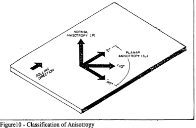
2.2.4 Anisotropy
Anisotropy or r-value as it is commonly known is an indication of the
directionality properties of sheet steel. Sheet steel exhibits directionality properties due to
properties in different directions. Anisotropy may be defined as the ratio of width strain
sw to thickness strain et of a tensile test specimen:
(13)
However, there are several methods of defining anisotropy. Planar anisotropy is defined
as:
r0 + rgo - 2r45 Ar =
---2 (14)
Normal anisotropy is defined as:
ro + 2r45 + no
rm ... ... ... (15) 4
where r0 is defined as the anisotropy in the direction of rolling, r45 is the anisotropy at 45
degrees to the direction of rolling and r90 is the anisotropy perpendicular to the direction
of rolling.
p l a n a r
[image:38.541.34.429.12.271.2]ANISOTROPY (&,)
Figure 10 - Classification of Anisotropy
The condition of Planar Anisotropy is undesirable in the drawing of cups as it
leads to a condition known as earing, where the top lip of the cup will be undulated and
non-uniform (see Figure 11). Normal Anisotropy is important for deep drawing operations
as it gives an indication of the materials resistance to thinning. Thus deep drawing steels
commonly have a high r-value (1.2-1.4) to enable deep draws with less chance of failure.
Drawing, in particular deep drawing, is sensitive to anisotropy. Drawing steels are
especially manufactured to have a higher r-value than ordinary steels. This allows the
material to stretch and plastically deform in the plane of the sheet and so assist in the
formation of deeply drawn components.
Troughs at 0°and
90° ' Balanced' Troughs at U S 0
Rolling direction
[image:38.541.35.335.534.668.2]2.3 Friction
Friction is very important in Deep Drawing of Sheet Steel. It has a large effect on
how sheet metal is restrained within a die and to what extent it is permitted to deform If
there is too much frictional force generated within a die set, excess tensile forces will be
generated in the sheet and tearing may take place. On the other hand, too little frictional
force being generated could allow compressive forces to be generated in the sheet which
could lead to wrinkling.
2.3.1 Basic Concepts
The basic concept of friction is demonstrated by considering a mass resting on a
horizontal plane. The mass will exert a force on the plane and the plane will exert an
equal and opposite force on the mass Fn. A tangential force Ft may be applied to cause the
mass to move. The amount of tangential force required to cause the mass to move is
generally considered to be the friction force and is a function of the mass-plane system.
This may also be quantified by Coulombs law:
Fr = P-Fn... (16)
where rj is defined as the co-efficient of friction. The frictional force Fr is said to be equal
to the product of the co-efficient of friction and the normal reaction force of the plane on
the mass [141].
2.3.2 Variables Affecting Friction
The Parameters which affect the frictional force in sheet metal forming are:
1 - Contact Pressure
Experiments show that dynamic friction, that is the frictional force
which must be overcome once the mass is in motion is smaller than
static friction, the frictional force required to initiate motion.
3 - Surface Roughness
The shape and density of surface asperities affect friction
regardless as to whether the surface is wet or dry.
4 - Lubrication and Debris
Lubrication has a very big effect on the frictional force. Type,
distribution and temperature sensitivity are important. Distribution
may be affected by forming pressure and sliding speed.
5 - Temperature
The local temperature at contact points on the binder surface and in
the lubricant is dependant upon plastic work dissipation and
thermal conductivity.
6 - Concurrent Deformation
This is important in sheet metal forming because the metal is
undergoing plastic deformation. Plastic deformation changes the
surface texture of the work material, changing the roughness and
opening up new surfaces by dislocation slip. All of the latter are
themselves very influential on the level of friction force.
2.3.3 Role of Lubricants
The role of lubricant in Sheet Metal Forming is primarily to reduce the frictional
lubricant. The first is that because there is less friction, there is less rubbing of the
surfaces. It is this rubbing of surfaces in the die which causes the die to wear. Thus the
use of lubricant aids in reducing the amount of wear which the dies receive. Secondly, the
rubbing of die surfaces can lead to surface defects known as galling and scoring. These
defects affect both the part and the die surface. The use of lubricant reduces both of these.
The rubbing between the die surfaces can lead to a build up of heat which adversely
affects the die surface. Lastly, the use of lubricant acts as a coating on the dies and
prevents the oxidation of the die surface.
The type of lubricants used are dependant upon the work surface. In sheet metal
forming for example, the die surface is tool steel or stainless steel. For these types of
surfaces, oil based solutions of fatty oils, waxes, polymers and pigmented soaps are
applicable [24].
Temperature can affect the lubricant by altering its properties. An increase in
temperature above room temperature can cause the lubricant to be less effective,
increasing the co-efficient of friction compared with no temperature change. Therefore,
increases in temperature above room temperature have a negative effect on the lubricant
and hence a negative effect on the process.
2.4 Limiting Draw Ratio
The limiting draw ratio or LDR is a common term in sheet metal forming which
gives an indication of a metals ability to sustain deformation in a cup drawing operation.
It is defined as the ratio of the largest blank-to-cup diameter that can be drawn
(17)
LDR = db
dp
where db is equal to the diameter of the blank whilst dp is equal to the diameter of the
CHAPTER 3
PREVIEW OF CURRENT AREAS OF RESEARCH
3.1 FE Analysis
A common tool for the investigation of Sheet Metal Forming is the use of the
Finite Element Method. Using this technique, the continuum or object to be modelled is
divided into a finite number of elements whose behaviour is specified by a finite number
of parameters. The solution of this complete system as an assembly of its elements
follows precisely the same rules as those applicable to standard discrete problems. Most
mathematical procedures of approximation fall into this category [127]. FE methods are
varied in the assumptions made and the problem at hand. Chou, Pan and Tang [17] for
example have presented a model using a stress resultant constitutive law where the effect
of thickness reduction due to large plastic deformation is considered. This is used in
conjunction with the principle of virtual work to derive a finite element formulation in
terms of stress resultants and their work-conjugate generalised strain rates. Alternatively,
Yang, Song and Yoo [131] proposed an adaptive bi-section refinement for rigid-plastic
finite element analysis. They proposed that any required order of surface conformity and
mesh refinement could be achieved be employing refinement according to the suggested
criterion. In this case, the suggested criterion was based on the thickness-modified
curvature of a general curved sheet surface.
Apart from this there has been much work using the Finite Element Method using
Simulation of the forming process of several stages of a car wheel disk with the inverse
3D Finite Element Code SIMEX. Several numerical results were predicted along with the
thickness of the part which was compared with experimental results using hot rolled steel
sheets with different properties and thickness. Rojek, Jovicevic and Onate [101] however
used the in-house explicit dynamic Code STAMPACK in order to analyse a number of
practical problems such as the stamping of a kitchen sink, hydraulic forming of an
aeronautical part and stamping of a food can. Their results showed a good comparison
with the actual part made.
3.2 Circle Grid Analysis
In addition to this, attempts have been made to improve Press Shop operations
using Circle Grid Analysis in conjunction with the Forming Limit Diagram
[3],[14],[59],[61],[66]. This is a useful tool used in Sheet Metal Forming enabling one to
determine how close to failure a particular part is approaching during a given forming
operation based upon the measurement of strain. The method involves electrochemically
etching a series of circles in a square grid pattem on a blank in the area of interest. A part
is then produced using this blank. The etched area of interest now contains a series of
ellipses within a distorted grid. The purpose of the circles-cum-ellipses is to determine
how much strain has taken place whilst the purpose of the grid is to determine what the
direction of the metal flow is.
A line is drawn through the section of panel of interest and the amount of strain
for each ellipse is determined by measuring the major and minor axis using a transparent
flexible ruler called a mylar tape. Thus for each deformed circle on the chosen line, there
plotted on what is known as a fotining limit diagrams. A forming limit diagram is shown
in Figure 12. The shape of the forming limit line is the same for all metals however its
position on the major axis is different for different metals. The point where the forming
— ao MAJOR STRETCH
— 6 0
YELLOW
__40
GREEN
— 20
— 10
— 40 — 30 — 20 — 10 0 10 20 30 4 0
MINOR STRE TCH
_______________________________________________________________________________________ I Figure 12 - Forming Limit Diagram
limit line intersects with the major axis is called the FLD0. FLD0 for metals is a function
of the material thickness (t) and work hardening exponent (n-value). It is defined by the
following function:
FLD0 = (23.2 + 14.17t). ——... (18)
A forming limit diagram is often represented with two forming limit lines. The
lower line intersects the major axis at FLD0 whilst the next one is generally 20% higher
and the uppermost zone, the “red” or forbidden zone. The data gathered for each
successive circle is plotted on the forming limit diagram and the "dots joined".
One is thus able to see where on the forming limit diagram one is currently
operating and how close one is to the marginal or forbidden zone. The forming limit
diagram also gives one an indication of which direction to move in if one is operating in
the marginal zone. This direction will correspond to some combination of major and
minor stretch which in turn will correspond to a new direction of flow of metal which
would be achieved using conventional methods (drawbeads, die modification).
Keeler [59] describes the construction and use of FLD's in order to determine what the
state of the metal is currently in. Using the FLD, one is able to determine whether there is
a tendency to wrinkle or split depending on the location on the FLD. This has been used
by Kolodziejski [66] where he outlines a method to design out surface defects in
stampings using grid straining in conjunction with FLD’s. Lee [69] describes a very
powerful method of analysing the grided and deformed panel using optical methods
combined with computer software in the analysis. It was traditionally the case that strain
was measured manually using a transparent strip commonly known as a Mylar Tape. Lee
however describes a much simpler and more powerful method whereby two photos of the
deformed panel are taken at different angles using a digital camera. The photos are then
analysed with computer software which then generates a 3D image of the deformed part
showing the levels of strain over the whole part.
3.3 Analytical Modelling
Besides the above methods, attempts have been made to model the Sheet Metal
Karafillis and Vaxevanidis for example used a theoretical model to predict the limit
strains and the forming limit diagrams of thin sheets subjected to biaxial stretching. Their
model correlated surface integrity changes resulting from mechanical processing; either
low-speed directional rolling or stochastic ball-drop forming and thermal stochastic
electro-discharge machining [76].
Perotti and Iuliano on the other hand calculated average powers and forces in
four-sided-piece deep-drawing based on the Upper Boundary Element Theorem
(U.B.E.T). This technique pre-supposes constancy of volume and the choice of a
kinetically admissible velocity distribution that meets the boundary conditions set by the
to ols. As deep-drawing proceeds, the distribution of the material flow may be determined.
This enables the calculation of strain rates and finally the power of deformation [94].
A totally different approach was taken by Jun, Lee and Yoo. They analysed cup
drawing using total strain energy theory assuming that the thickness of the sheet remained
constant during drawing. This enabled them to obtain the load-stroke curve and a
relationship which can predict limiting drawing ratio [53].
3.4 Experimental Approaches
Although unique in its own right, this project was by no means the first to adopt a
pragmatic hands on approach to solving sheet metal forming problems. Keeler [60],[61]
and [62] has demonstrated on many occasions the need to understand Stamping
Operations, a very complex manufacturing environment, as a Black Box system such that
one is in a better position to solve problems in a systematic and logical manner. He along
with others [66] have demonstrated how Circle Grid Analysis in conjunction with the use
problems. Keeler also emphasises the need to obtain good quantitative data on the
stamping process. This is demonstrated by the fact that the correct values of critical
forming characteristics required to solve the many problems are known, yet the exact
magnitude of these values is not. For example, it is possible to say that a higher r-value
will improve the drawability of a steel, yet the exact increase in r corresponding to better
drawability is not known. Therefore, systems predicting sheet metal formability are only
as good as the data being fed into the systems [58] and it is Design of Experiments which
will target the type of problems mentioned above more effectively.
Design of Experiments techniques have been successfully used in an industrial
environment to tackle real problems. This inevitably involves reducing variability in a
process to ensure that the inputs do not vary, or if they do, to try to minimise the range of
variation [90]. It is also necessary to understand the nature of the variation such that
CHAPTER 4
PROCESS VARIABLES
4.1 Introduction
There have been many variables identified which all have some control over sheet
metal forming. The following list shows the variables which may effect the stamping of
sheet metal. This list is rather general and would apply to most press shops around the
world - at least where automobile parts are being made.
This doesn't however take into account other variables which may be
characteristics of a particular part. For example, the draw die of a bodyside may
incorporate nitrogen cylinders, balance blocks and springs to aid in restricting metal flow
and thus enable a split and wrinkle free part to be produced. Nitrogen cylinder pressure
and spring stiffness is not generally included in a list of press shop variables yet for the
production staff, a shift in this type of variable will no doubt affect the part quality and is
therefore very important and must be considered when analysing this die set.
Therefore, one may appreciate the subtle complexities of press operations where it
is beneficial to look at the press shop as a system and try to incorporate all variables in an
attempt to stabilise the system, however, one cannot be allowed to forget that there will
usually be more variables and points to take into consideration when trying to improve
the quality of a particular part and the amount of'hidden variables' will depend upon the
complexity of the part - confirming the common belief that "each job must be judged on
4.2 Input Variables
The input variables identified below were those observed during an in plant study,
many of which were characterised by Siekirk[l 11]:
l.Shut Height - The vertical distance between the bottom of the lower half of a die
to the top of the top half of a die when the press ram is at bottom dead
centre. With respect to the blankholder, it affects how much force is being
applied to the blankholder. The lower the shut height, the more the blank
is being compressed between the two die halves. This means that the metal
will not flow as easily either eliminating wrinkles, introducing splits or
both or neither. For many parts, it is the primary method of adjusting the
amount of frictional clamping force induced by the blankholder. With
regard to the punch, the shut height will affect the amount of deformation
which the blank will undergo. A shut height which is too high for example
could lead to insufficient form/deformation whilst a shut height which is
too low could cause the metal to thin unnecessarily, the extreme case
being splits.
2. Corner Pressure - Comer Pressure is a convenient way of applying more or
less force to the comers of the part. Comer pressure control is really
part of the overload protection system of large mechanical presses.
Force is not transmitted directly to the ram of a press through a
mechanical linkage as one might imagine. Instead, it is transferred through
a narrow interface of oil in a chamber under pressure. The reason for this
would prevent the ram from reaching bottom dead centre inducing much
larger forces in the press structure and crown then would otherwise be
experienced in a normal cycle.
The momentum of a press mechanism is such that
these large forces induced would be transferred not only to the die but also
upward and throughout the whole press. This could lead to bent or broken
cranks and other vital pieces of machinery. In an attempt to counter this
scenario, force is transferred, as previously, stated through a reservoir of
oil. Should the oil pressure in this reservoir exceed some set limit, then all
of the oil in the reservoirs of each point of suspension will dump into a
common tank giving a clearance of approximately an eighth of an inch. It
is possible during normal press operation to vary the pressure of oil in
each reservoir.
This will affect how much force is applied at the point of
suspension in question. Therefore, one may affect the amount of frictional
clamping force acting at the blankholder at a particular comer though not
to the same degree as with shut height. During on plant experimentation,
for a 700 ton blankholder, it was possible to vary the force from between
350 tons to 800 tons (according to the specifications).
3.Blank Location - The blank location is essentially self explanatory. It is simply
where the blank is positioned with respect to some fixed reference point
on the die surface. The effect of blank location can be quite
the flow of metal and the secondary effect which can be observed is the
final length of flanges which are a concern in assembly. A blank which
has been incorrectly located can cause insufficient amount of metal at a
particular location. If this location happens to be where the part is welded
to another part in later assembly operations, then this insufficient amount
of metal will mean that there is not enough metal to create a sufficient
join.
4. Blank Geometry - This variable too, should be self explanatory. There generally
is an optimum blank size. A blank which is too large may cause wrinkling
or may simply be a waste of metal. On the other hand, a blank which is too
small will be a constant source of trouble to toolmakers because they will
be continually having to make adjustments to the press and die in order to
get the positioning and other variables just right in order to get a part with
sufficient form.
5. Draw Speed - This refers to the speed of the Ram as the Press cycles. It is
achieved by varying the current in the magnetic clutch and brake
mechanism. This will effect the rate of deformation. This variable effects
the punch much more than the blankholder.
6. Lubrication - The amount of lubrication applied to the blank will greatly effect
the nature of the ensuing draw. Some parts are very critical, involving
complicated form and/or high rates of deformation. In these cases,
experience has shown that it is almost impossible to run these parts
general methods of applying lubricant to a panel. The first is a
roller coater which consists basically of two contra-rotating rolls which
have lubricant applied to them, the panel is forced in-between these rolls
and thus has a film of lubricant applied. The second method is by using
spray units. This set-up consists basically of 4 or less spray guns located
generally on the four comers of a die. These are focused onto difficult
areas and spray automatically as a press cycles. This has the advantage of
considerable savings in lubricant.
The last set-up is a blankwasher which washes the blanks using
brush rolls and squeegee rolls and applies a film of lubricant similar to a
roller coater in the last set of rolls. Lubricant is the most effective way of
controlling friction. It is also one of the most difficult variables to control.
7. Blank Thickness - Blank thickness will effect the force needed to form a blank,
final part strength and resistance to deformation. Blank thickness will also
effect tool design. This is because a thicker blank will require a larger
clearance in between the die halves, it will also not bend over as small a
radius as a thinner blank and since it requires more work to deform may
also require more generous radii within the die. Generally speaking, effort
is always being directed into reducing blank thickness in order to save
weight and manufacturing costs.
8. Mechanical Properties o f Work Material - There are approximately seven
different characteristics which are used to describe the mechanical
strength, tensile strength, elongation, hardness, uniform elongation,
anisotropy and the work hardening index. Yield strength and tensile
strength will effect the forming loads whilst elongation, anisotropy,
hardness and work hardening index will effect the formability
(drawability, stretchability). It is desired to make the stamping process
robust enough such that inherent variability in sheet steel has no real effect
on sheet metal formability.
9. Coating o f Work Material - Most steel is delivered to the Stamping Plant with a
coating of oil usually called mill oil. This is an anti-corrosion measure
while steel coils are in storage however the technology of these oils has
progressed to the stage where the oil has qualities enabling it to be used as
a drawing compound or lubricant. There are cases where the viscosity is
insufficient to enable it to be used as such. In this case, lubricant is
applied directly over it as described in section 2.3.3. This has proved to be
satisfactory although it might be interesting to see the effects of the
interaction between mill oil and lubricant. Other types of coatings are
applied to sheet steel before it arrives in a stamping plant as anti
corrosion agents for the finished product. Common coatings include zinc
phophatization plus anaphoresis, iron phosphatization plus cataphoresis
and zinc phophatization plus cataphoresis. Zinc phosphatization plus
cataphoresis is generally better than iron phosphatization plus
cataphoresis and zinc phosphatization plus naphoresis. Formability is
![Figure 14 - Hydraulic Overload System (Demands on Present Day Presses[43])](https://thumb-us.123doks.com/thumbv2/123dok_us/1933513.152987/64.541.39.320.143.564/figure-hydraulic-overload-demands-present-day-presses.webp)


![The Renewable Energy Progress Report: Commission Report in accordance with Article 3 of Directive 2001/77/EC, Article 4(2) of Directive 2003/30/EC and on the implementation of the EU Biomass Action Plan, COM (2005) 628 [SEC (2009) 503 final]. COM (2009) 1](data:image/gif;base64,R0lGODlhAQABAIAAAP///wAAACH5BAEAAAAALAAAAAABAAEAAAICRAEAOw==)