Peer-to-Peer Grids
Geoffrey Fox1,2,4, Dennis Gannon2,Sung-Hoon Ko1, Sangmi Lee5, Shrideep Pallickara1, Marlon Pierce1, Xiaohong Qiu1,3, Xi
Rao1,2, Ahmet Uyar1,3, Minjun Wang1,3, Wenjun Wu1 1Community Grid Computing Laboratory, Indiana University
501 N Morton Suite 224, Bloomington IN 47404 2Computer Science Department, Indiana University
3EECS Department, Syracuse University
4School of Informatics and Physics Department, Indiana University 5Computer Science Department Florida State University
[email protected], [email protected], [email protected],
[email protected], [email protected], [email protected], [email protected],
[email protected], [email protected], [email protected], [email protected]
Keywords: Web Service, Event Service, JXTA, JMS, Java Message Service, Collaboration, Universal Access, Peer-to-Peer Abstract
We describe Peer-to-Peer Grids built around Integration of technologies from the peer-to-peer and Grid fields. We focus on the role of Web services linked by a powerful event service using uniform XML interfaces and application level routing. We describe how a rich synchronous and asynchronous collaboration environment can support virtual communities built on top of such infrastructure. Universal access mechanisms are discussed.
1 Peer-to-Peer Grids
There are no crisp definitions of Grids [1,2] and Peer-to-Peer Networks [3] that allow us to unambiguously discuss their differences and similarities and what it means to integrate them. However these two concepts conjure up stereotype images that can be compared. Taking “extreme” cases, Grids are exemplified by the infrastructure used to allow seamless access to supercomputers and their datasets. P2P technology is exemplified by Napster and Gnutella, which can enable ad hoc communities of low-end clients to advertise and access the files on the communal computers. Each of these examples offers services but they differ in their functionality and style of implementation. The P2P example could involve services to set-up and join peer groups, browse and access files on a peer, or possibly to advertise one’s interest in a particular file. The “classic” grid could support job submittal and status services and access to sophisticated data management systems. Grids typically have structured robust security services while P2P networks can exhibit more intuitive trust mechanisms reminiscent of the “real world”. Again Grids typically offer robust services that scale well in pre-existing hierarchically arranged organizations; P2P networks are often used when a best effort service is needed in a dynamic poorly structured community. If one needs a particular “hot digital recording”, it is not necessary to locate all sources of this; a P2P network needs to search enough plausible resources that success is statistically guaranteed. On the other hand, a 3D simulation of the universe might need to be carefully scheduled and submitted in a guaranteed fashion to one of the handful of available supercomputers that can support it.
In this article, we explore the concept of a Peer-to-Peer Grid with a set of services that include those of Grids and P2P networks and support naturally environments that have features of both limiting cases. We can discuss two examples where such a model is naturally applied. In High Energy Physics data analysis (e-Science [4]) problem discussed in chapter of Bunn and Newman, the initial steps are dominated by the systematic analysis of the accelerator data to produce summary events roughly at the level of sets of particles. This Grid-like step is followed by “physics analysis” which can involve many different studies and much debate between involved physicists as to appropriate methods to study the data. Here we see some Grid and some P2P features. As a second example, consider the way one uses the Internet to access information – either news items or multimedia entertainment. Perhaps the large sites like Yahoo, CNN and future digital movie distribution centers have Grid like organization. There are well-defined central repositories and high performance delivery mechanisms involving caching to support access. Security is likely to be strict for premium channels. This structured information is augmented by the P2P mechanisms popularized by Napster with communities sharing MP3 and other treasures in a less organized and controlled fashion. These simple examples suggest that whether for science or commodity communities, information systems should support both Grid and Peer-to-Peer capabilities [5,6].
2 Key Technology Concepts for P2P Grids
Database Database
Broker
Computing Security Collaboration
Composition Content Access Resources
Clients Users and Devices
Middle Tier of Web Services Brokers Service Providers
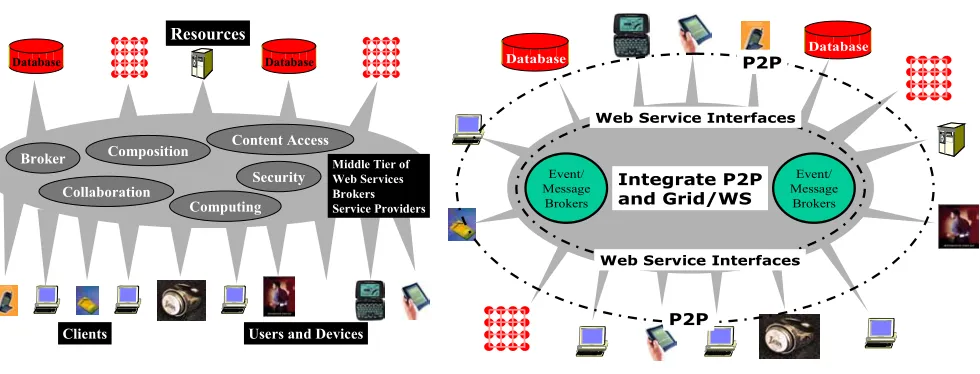
The other chapters in this book describe the essential architectural features of Web services and we first contrast their application in Grid and P2P systems. Fig. 1 shows a traditional Grid with a Web (OGSA) middleware mediating
between clients and back-end resources. Fig. 2 shows the same capabilities but arranged democratically as in a P2P environment. There are some “real things” (users, computers, instruments), which we term external resources – these are the outer band around the “middleware egg”. As shown in fig. 3, these are linked by a collection of Web Services [7]. All entities (external resources) are linked by messages whose communication forms a distributed system integrating the component parts.
Peer to Peer Grid
Database Database
P2P
P2P
Web Service Interfaces
Web Service Interfaces Event/
Message Brokers
Integrate P2P and Grid/WS
Event/ Message
Brokers
[image:2.612.60.550.71.258.2]Fig. 2: A Peer-to-Peer Grid Fig. 1: A Grid with clients accessing back-end
resources through middle-ware services
Distributed Object technology is implemented with objects defined in a XML-based IDL (Interface Definition Language) called WSDL (Web Services Definition
Language). This allows “traditional approaches” like CORBA or Java to be used “under-the-hood” with an XML wrapper providing a uniform interface. Another key concept – that of the resource – comes from the web consortium W3C. Everything – whether an external or internal entity – is a resource labeled by a URI (Universal Resource Identifier); a typical form being escience://myplace/mything/mypropertygroup/leaf. This includes not only macroscopic constructs like computer programs or sensors but also their detailed properties. One can consider the URI as the barcode of the Internet – it labels everything. There are also of course URL’s (Universal Resource Locations) which tell you where things are. One can equate these concepts (URI and URL) but this is in principle inadvisable although of course common practice.
(Virtual) XML Knowledge (User) Interface
Clients
(Virtual) XML Data Interface Raw Data Raw
Resources Raw Data
WS WS
Web Service (WS)
WS
WS
WS WS WS
WS
Render to XML Display Format
(Virtual) XML Rendering Interface etc.
[image:2.612.59.282.322.477.2]XML WS to WS Interfaces
Fig. 3: Role of Web Services (WS) and XML in linkage of clients and raw resources
Finally the environments of figs. 1 to 3 are built in a service model. A service is an entity that accepts one or more inputs and gives one or more results. These inputs and results are the messages that characterize the system. In WSDL, the inputs and outputs are termed ports and WSDL defines an overall structure for the messages. The resultant environment is built in terms of the composition of services.
different sources. This picture is consistent with that described throughout this book with perhaps this chapter emphasizing more the basic concept of resources communicating with messages.
There are several important technology research and development areas on which the above infrastructure builds 1) Basic system capabilities packaged as Web Services. These include security, access to computers (job submittal, status
etc.) and access to various forms of databases (information services) including relational systems, LDAP, and XML databases/files. Network wide search techniques about web services or the content of web services could be included here. In sec. 1, we described how P2P and Grid systems exhibited these services but with different trade-offs in performance, robustness and tolerance of local dynamic characteristics.
2) The messaging sub-system between Web Services and external resources addressing functionality, performance and fault-tolerance.
Both P2P and Grids need messaging although if you compare JXTA [8] as a typical P2P environment with a Web Service based Grid you will see important differences described in sec. 3. Items 3) to 7) below are critical e-Science [4] capabilities which can be used more or less independently
3) Tool-kits to enable applications to be packaged as Web Services and construction of “libraries’ or more precisely components. Near-term targets include areas like image processing used in virtual observatory projects or gene searching used in bio-informatics.
4) Application meta-data needed to describe all stages of the scientific endeavor.
5) Higher-level and value-added system services such as network monitoring, collaboration and visualization. Collaboration is described in sec. 4 and can use a common mechanism for both P2P and Grids.
6) What has been called the Semantic Grid [9] or approaches to the representation of and discovery of knowledge from Grid resources. This is discussed in detail in the chapter by de Roure and collaborators.
7) Portal technology defining user facing ports on web services which accept user control and deliver user interfaces. Fig. 3 is drawn as a classic 3-tier architecture: client (at the bottom), back-end resource (at the top) and multiple layers of middleware (constructed as web services). This is the natural virtual machine seen by a given user accessing a resource. However the implementation could be very different. Access to services can be mediated by “servers in the core” or alternatively by direct peer-to-peer (P2P) interactions between machines “on the edge”. The distributed object abstractions with separate service and message layers allow either P2P or server-based implementations. The relative performance of each
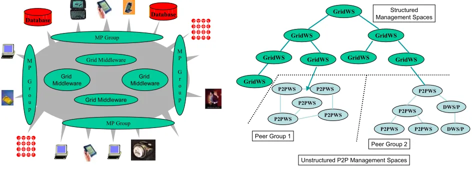
approach (which could reflect computer/network horsepower as well as existence of firewalls) would be used in deciding on the implementation to use. P2P approaches best support local dynamic interactions; the server approach scales best globally but cannot easily manage the rich structure of transient services, which would characterize complex tasks. We refer to our architecture as a peer-to-peer grid with peer groups managed locally arranged into a global system supported by core servers. Fig. 4 redraws fig. 2 with Grids controlling central services while “services at the edge” are grouped into less organized “middleware peer groups”. Often one associates P2P technologies with clients but in a unified model, they provide services, which are (by definition) part of the middleware. As an example, one can use the JXTA search technology [8] to federate middle tier database systems; this dynamic federation can use either P2P or more robust Grid security mechanisms. One ends up with a model shown in fig. 5 for managing and organizing services. There is a mix of structured (Grid-like) and
unstructured dynamic (P2P like) services.
Database Database
Grid Middleware Grid Middleware
Grid
Middleware MiddlewareGrid
MP Group MP Group
M P
G r o u p
M P
G r o u p
Unstructured P2P Management Spaces GridWS
GridWS GridWS
GridWS
GridWS GridWS GridWS GridWS
P2PWS P2PWS
P2PWS P2PWS
P2PWS
DWS/P P2PWS
P2PWS
DWS/P
P2PWS P2PWS Structured Management Spaces
Peer Group 1
Peer Group 2
[image:3.612.67.540.380.550.2]Fig. 5: A hierarchy of Grid (Web) Services with dynamic P2P groups at the leaves Fig. 4: Middleware Peer (MP) Groups of Services at
We can ask if this new approach to distributed system infrastructure affects key hardware, software infrastructure and their performance requirements. First we present some general remarks. Servers tend to be highly reliable these days. Typically they run in controlled environments but also their software can be proactively configured to ensure reliable operation. One can expect servers to run for months on end and often one can ensure that they are modern hardware configured for the job at hand. Clients on the other hand can be quite erratic with unexpected crashes and network disconnections as well as sporadic connection typical of portable devices. Transient material can be stored on clients but permanent information repositories must be on servers – here we talk about “logical” servers as we may implement a session entirely within a local peer group of “clients”. Robustness of servers needs to be addressed in a dynamic fashion and on a scale greater than in previous systems. However traditional techniques – replication and careful transaction processing – probably can be extended to handle servers and the web services that they host. Clients realistically must be assumed to be both unreliable and sort of outside our control. Some clients will be “antiques” and underpowered and are likely to have many software hardware and network instabilities. In the simplest model clients “just” act as a vehicle to render information for the user with all the action on “reliable” servers. Here applications like Microsoft Word “should be” packaged as Web services with message based input and output. Of course if you have a wonderful robust PC you can run both server(s) and thin client on this system.
3 Peer-to-Peer Grid Event Service
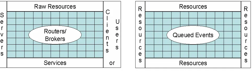
[image:4.612.64.546.391.529.2]Here we consider the communication subsystem, which provides the messaging between the resources and Web services. Its characteristics are of a Jekyll and Hyde nature. Examining the growing power of optical networks we see the increasing universal bandwidth that in fact motivates the thin client and server based application model. However the real world also shows slow networks (such as dial-ups), links leading to a high fraction of dropped packets and firewalls stopping our elegant application channels dead in their tracks. We also see some chaos today in the telecom industry which is stunting somewhat the rapid deployment of modern “wired’ (optical) and wireless networks. We suggest that key to future e-Science infrastructure will be messaging subsystems that manage the communication between external resources, web services and clients to achieve the highest possible system performance and reliability. We suggest this problem is sufficiently hard that we only need solve this problem “once” i.e. that all communication – whether TCP/IP, UDP, RTP, RMI, XML or you-name-it be handled by a single messaging or event subsystem. Note this implies we would tend to separate control and high volume data transfer reserving specialized protocols for the latter and more flexible robust approaches for setting up the control channels.
[image:4.612.57.311.394.523.2]Fig. 7: Simplest View of System Components showing routers of event service supporting queues Fig. 6: One View of System Components with event
service represented by central mesh
natural to employ routers or brokers whose function is to distribute messages between the raw resources, clients and servers of the system. In JXTA, these routers are termed rendezvous peers.
We consider that the servers provide services (perhaps defined in the WSDL [7] and related XML standards [10]) and do NOT distinguish at this level between what is provided (a service) and what is providing it (a server). Note that we do not distinguish between events and messages; an event is defined by some XML Schema including a time-stamp but the latter can of course be absent to allow a simple message to be thought of as an event. Note an event is itself a resource and might be archived in a database raw resource. Routers and brokers actually provide a service – the management of (queued events) and so these can themselves be considered as the servers corresponding to the event or message service. This will be discussed a little later as shown in fig. 9. Here we note that we design our event systems to support some variant of the publish-subscribe mechanism. Messages are queued from “publishers” and then clients subscribe to them. XML tag values are used to define the “topics” or “properties” that label the queues.
Note that in fig. 3, we call the XML Interfaces “virtual”. This signifies that the interface is logically defined by an XML Schema but could in fact be implemented differently. As a trivial example, one might use a different syntax with say <sender>meoryou</sender> replaced by
sender:meoryou which is an easier to parse but less powerful notation. Such simpler syntax seems a good idea for “flat” Schemas that can be mapped into it. Less trivially, we could define a linear algebra web service in WSDL but compile it into method calls to a Scalapack routine for high performance implementation. This compilation step would replace the XML SOAP based messaging [10] with serialized method arguments of the default remote invocation of this service by the natural in memory stack based use of pointers to binary representations of the arguments. Note that we like publish-subscribe messaging mechanisms but this is sometimes unnecessary and indeed occurs unacceptable overhead. We term the message queues in figs. 7 and 9 virtual to indicate that the implicit publish-subscribe mechanism can be bypassed if this agreed in initial negotiation of communication channel. The use of virtual queues and virtual XML specifications could suggest the interest in new run-time compilation techniques, which could replace these universal but at times unnecessarily slow technologies by optimized implementations.
Data base
Resource
Broker
Broker Broker Broker
Broker
Broker
Software multicast (P2P) Community
(P2P) Community (P2P) Community
[image:5.612.58.299.198.373.2](P2P) Community
Fig. 8: Distributed Brokers Implementing Event Service
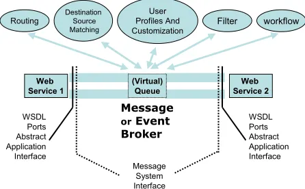
We gather together all services that operate on messages in ways that are largely independent of the process (Web service) that produced the message. These are services that depend on “message header” (such as destination), message format (such as multimedia codec) or message process (as described later for the publish-subscribe or workflow mechanism).
Security could also be included here. One could build such capabilities into each Web service but this is like “inlining” (more efficient but a job for the run-time compiler we mentioned above). Fig. 9 shows the event or message
architecture, which supports communication channels between Web services which can either be direct or pass through some mechanism allowing various services on the events. These could be low-level such as routing between a known source and destination or the higher-level publish-subscribe mechanism that identifies the destinations for a given pu event. Some routing mechanisms in peer-to-peer systems in fact use dynamic strategies that merge these high and low lev approaches to communication. Note that the messages must support multiple interfaces: as a “physical” message it should support SOAP; above this the event service should support added capabilities such as filtering, publish-subscribe, collaboration, workflow which corresponds to changing message content or delivery. Above this there are application and service standards. All of these are defined in XML, whi can be virtualized. As an example, consider an audio-video conferencing web service [16,17]. It could use a simple publish/subscribe mechanism to advertise the availability of some video feed. A client interested in receiving the video w negotiate (using the SIP protocol perhaps) the transmission details. The video could either be sent directly from publisher to
Web Service 1
(Virtual) Queue
Web Service 2
WSDL Ports Abstract Application Interface
Message
orEvent Broker
WSDL Ports Abstract Application Interface Message
System Interface
Destination Source
Matching Filter
Routing Profiles AndUser workflow
Customization
Fig 9: Communication Model showing Sub-services of Event Service
blished
el
ch
[image:5.612.60.283.482.620.2]subscriber; alternatively from publisher to web service and then from web service to subscriber; as a third option, we could send from the web service to the client but passing through a filter that converted one codec into another if required. In the last case, the location of the filter would be negotiated based on computer/network performance issues – it might also involve proprietary software only available at special locations. The choice and details of these three different video transport and filtering strategies would be chosen at the initial negotiation and one would at this stage “compile” a generic interface to its chosen form. One could of course allow dynamic “run-time compilation” when the event processing strategy needs to cha during a particular stream. This scenario is not meant to be innovative but rather to illustrate the purpose of our architect building blocks in a homely example. Web services are particularly attractive due to their support of interoperabili allows the choices described.
nge ure ty, which
We have designed and implemented a system NaradaBrokering supporting the model described here with a dynamic collection of brokers supporting a generalized publish-subscribe mechanism. As described elsewhere [5,6,12,13,14] this can operate either in a client-server mode like JMS or in a completely distributed JXTA-like peer-to-peer mode. By combining these two disparate models, NaradaBrokering can allow optimized performance-functionality trade-offs for different scenarios. Note that typical overheads for broker processing are around one millisecond. This is acceptable for real-time collaboration [6,15,17] and even audio-video conferencing where each frame takes around 30 milliseconds. We have demonstrated that such a general messaging system can be applied to real-time synchronous collaboration using the commercial Anabas infrastructure [15,18].
4 Collaboration in P2P Grids
Both Grids and P2P networks are associated with collaborative environments. P2P networks started with ad-hoc communities such as those sharing MP3 files; Grids support virtual enterprises or organizations – these are unstructured and structured societies respectively. At a high level collaboration involves sharing and in our context this is sharing of Web Services, objects or resources. These are in principle essentially the same thing although today sharing “legacy applications” like Microsoft Word is not so usefully considered as sharing Web services. Nevertheless we can expect that Web Service interfaces to “everything” will be available and will take this point of view below where Word, a Web Page, a computer visualization or the audio-video (at say 30 frames per second) from some video-conferencing system will all be viewed as objects or resources with a known Web service interface. Of course, if you want to implement collaborative systems today, then one must use Microsoft COM as the object model for Word but architecturally at least, this is similar to a Web service interface.
There are many styles and approaches to collaboration. In asynchronous collaboration, different members of a community access the same resource; the Web has revolutionized asynchronous collaboration with in its simplest form, one member posting or updating a web page, and others accessing it. Asynchronous collaboration has no special time constraint and typically each community member can access the resource in their own fashion; objects are often shared in a coarse grain fashion with a shared URL pointing to a large amount of information. Asynchronous collaboration is quite fault-tolerant as each user can manage their access to the resource and accommodate difficulties such as poor network connectivity; further well-established caching techniques can usually be used to improve access performance as the resource is not expected to change rapidly. Synchronous collaboration is at a high level no different from the asynchronous case except that the sharing of information is done in real-time. The “real-time” constraint implies delays of around 10-1000 msec. per participant or rather “jitter in transit delays” of a “few” msecs. Note these timing can be compared to the second or so it takes a browser to load a new page; the several seconds it takes a lecturer to gather thoughts at the start of a new topic (new PowerPoint slide); and the 30 msec. frame size natural in audio/video transmission. These numbers are much longer than the parallel computing MPI message latency measured in microsecond(s) and even the 0.5-3 msec. typical latency of a middle-tier broker.
The sharing mechanism can be roughly the same for both synchronous and asynchronous case. One needs to establish communities (peer groups) by either direct (members join a session) or indirect (members express interest in topics
and are given opportunity to satisfy this interest). The indirect mechanism is most powerful and is familiar in P2P systems with JXTA using XML expressed advertisements to link together those interested in a particular topic. Audio-video conferencing systems typically have a direct method with perhaps email used to alert potential attendees of an upcoming session. Commercial web-conferencing systems like WebEx and Placeware use this approach. In
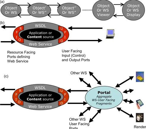
asynchronous collaboration, one typically “just” has notification mechanisms for object availability and update. Systems like CVS (version control) and WebDAV (distributed authoring) are particularly sophisticated in this regard. However such sharing environments do not usually support the “microscopic” events as say one user edits a file; rather “major events” (check-in and check-out) are communicated between participants. Nevertheless it is worth stressing that asynchronous collaboration can be supported through the generalized publish-subscribe mechanism with events (messages, advertisements) being linked together to define the collaboration. In order to describe a general approach to collaboration, we need to assume that every Web service has one or more ports in each of three classes shown in fig. 10(b). The first class are (resource-facing) input ports which supply the information needed to define the state of the Web service; these may be augmented by user-facing input port(s) that allow control information to be passed by the user. The final class is user-facing output ports that supply information needed to construct the user interface. Asynchronous collaboration can share the data (e.g. URL for a Web page or body of an email message) needed to define a Web service (display Web page or browse e-mail in examples).
Object
Or WS Or WS’’Object’ Object’’Or WS”
Object Or WS Display Object Or WS Viewer User Facing Input (Control) and Output Ports Resource Facing Ports defining Web Service (a) (b) Application or
Content source
WSDL Web Service F I U O F I R O Application or
Content source
WSDL Web Service F I U O F I R O Portal Aggregate WS-User Facing Fragments Render Other WS User Facing Ports Other WS (c)
Fig 10 (a) Web Service pipeline (flow) from originating resource(s) (objects) to display
(b) Web services can have resource facing and user facing ports
(c) Portal as part of display “Web service” aggregating user facing fragments from multiple Web Services
Let us now consider synchronous collaboration. If one examines an object, then there is typically some pipeline as seen in fig. 10(a) from the original object to the eventual displayed user interface; as described above, let us assume that each stage of the pipeline is a Web service with data flowing from one to another. Other chapters have discussed this composition or flow problem for Web Services and our discussion is not sensitive to details of linkages between Web services. Rather than a simple pipeline, one can have a complex dynamic graph linking services together. Fig 10(c) shows the role of portals in this approach and we will return to this in sec. 5. One can get different types of sharing depending on which “view” of the
nd shares the flow of information after this interception. can identify three particularly important cases illustrat figures 11, 12 and 13; these are shared display, shared inpu port and shared user-facing output port. The shared input port case is usually called “shared event” but in fact in a modern architecture with all resources communicating by messages, all collaboration modes can be implemen a similar event mechanism. The commercial Anabas environment uses the Java Message Service JMS to handle all collaboration modes and we have successfully use NaradaBrokering to replace JMS. In each collaboration mode we assume there is a single “master” client which “controls” the Web service; one can in fact have much m complex scenarios with simultaneous and interchangeable control. However in all cases, there is instantaneously one “master” and one must transmit the state as seen by this system to all other participants.
In shared display model of fig. 11, one shares the bitmap
basic object one shares i.e. on where one intercepts the pipeline a We
ed in t
ted with
d
ore
(vector) display and the state is maintained between the clients by transmitting (with suitable compression) the changes in the display. As with video compression like MPEG, one
Shared Display
WS Display WS Display Event (Message) Service Other Participants Object Or WS Display Object Or WS Viewer ObjectOr WS Or WS’’Object’ Object’’Or WS”
Master
[image:7.612.58.304.95.313.2]uses multiple event types with some defining full display and others just giving updates. Obviously the complete display requires substantial network bandwidth but it is useful every now and then so that one can support clients joining throughou session, has more fault tolerance and can define full display update points (major events) where asynchronous clients can a recording. Supporting heterogeneous clients requires that sophisticated shared display environments automatically change size and color resolution to suit each community member. Shared display has one key advantage – it can immediately be applied to all shared objects; it has two obvious disadvantages – it is rather difficult to customize and requires substantial network bandwidth.
In the shared input port (or input message) model of fig. 12, one replicates the Web service to be shared with one copy for each client.
t join
Then sharing is achieved by intercepting the pipeline before the master web service and directing copies of the m
a to all d as om nt
h the
ts giving
a messag on
i-d es e to all d as om nt
h the
ts giving
a messag on
i-d
es
e
essages on each input port of the “master” Web service to the replicated copies. Only the user-facing ports in this model are typically partially shared with data from the master transmitted to each replicated Web service but in way that can be overridden on each client. We can illustrate this with a more familiar PowerPoint example. Here all the clients have a copy of the PowerPoint application and the presentation to be shared. On the master client, one uses some sort of COM wrapper detect PowerPoint change events such as slide and animation changes. These “change” events are sent to participating clients. This model isn’t usually phrase “shared input ports” but that’s just because PowerPoint as currently shipped is not set up as a Web service with a messaging interface. One can build a similar shared Web browser and for some browsers (such as that for SVG fr Apache) one can in fact directly implement the Web service model. There is a variant here as one can either trap internal events (such as slide changes in PowerPoi or textareas changes in a browser) or the external mouse and keyboard events that generated them. We once nt model to trap user input to a browser. These events were ared input port model with the user interface playing role of input ports. We can hope that developments [19] such as WSRP and WSIA (Web services for Remote Portals and Interactive Applications) will define user-facing message ports and the interactions of Web services with input devices so
that a coherent systematic approach can be given for replicated Web services with shared input ports.
The shared output port model of fig 13 only involves a single Web service with user-facing por
familiar PowerPoint example. Here all the clients have a copy of the PowerPoint application and the presentation to be shared. On the master client, one uses some sort of COM wrapper detect PowerPoint change events such as slide and animation changes. These “change” events are sent to participating clients. This model isn’t usually phrase “shared input ports” but that’s just because PowerPoint as currently shipped is not set up as a Web service with a messaging interface. One can build a similar shared Web browser and for some browsers (such as that for SVG fr Apache) one can in fact directly implement the Web service model. There is a variant here as one can either trap internal events (such as slide changes in PowerPoi or textareas changes in a browser) or the external mouse and keyboard events that generated them. We once nt model to trap user input to a browser. These events were ared input port model with the user interface playing role of input ports. We can hope that developments [19] such as WSRP and WSIA (Web services for Remote Portals and Interactive Applications) will define user-facing message ports and the interactions of Web services with input devices so
that a coherent systematic approach can be given for replicated Web services with shared input ports.
The shared output port model of fig 13 only involves a single Web service with user-facing por
Shared Output Port Collaboration
Shared Input Port (Replicated WS) Collaboration
de
tra s
de
tra s
WS Display WS Viewer WS Display WS Viewer Event (Message) Service Master WS Display WS Viewer
Collaboration as a WS Set up Session
[image:8.612.62.314.191.362.2]Web Service F I U O F I R O Other Participants Web Service F I U O F I R O Web Service F I U O F I R O
Fig. 12: Shared Web Services using Input Ports (messages) veloped a sophisticated shared browser using the JavaScript eve
nsmitted directly to participating clients to implement such a veloped a sophisticated shared browser using the JavaScript eve
nsmitted directly to participating clients to implement such a
ing interface to the client. As in the next secti and fig. 10(c), a portal could manage these user-facing ports. As (by definition) the user-facing ports of a Web service define the user interface, this mechanism simply gives a collaborative version of any Web service. One simple example can be built around any content or mult media server with multi-cast output stream(s). This metho naturally gives, like shared display, an identical view for each user but with the advantage of typically less network bandwidth since the bitmap display usually is more voluminous than the data transmitted to the client to define the display. In the next section, we discuss user interfac and suggest that the user facing ports should not directly define the interface but a menu allowing the client to choose the interface style. In such a case, one can obtain from the shared user-facing model, collaborative views rvice model of fig. 12 offers even greater customizability
shared Web service.
ing interface to the client. As in the next secti and fig. 10(c), a portal could manage these user-facing ports. As (by definition) the user-facing ports of a Web service define the user interface, this mechanism simply gives a collaborative version of any Web service. One simple example can be built around any content or mult media server with multi-cast output stream(s). This metho naturally gives, like shared display, an identical view for each user but with the advantage of typically less network bandwidth since the bitmap display usually is more voluminous than the data transmitted to the client to define the display. In the next section, we discuss user interfac and suggest that the user facing ports should not directly define the interface but a menu allowing the client to choose the interface style. In such a case, one can obtain from the shared user-facing model, collaborative views rvice model of fig. 12 offers even greater customizability
shared Web service. tha ed for each user. Of course the replicated Web s
as each client has the freedom to accept or reject data defining the tha ed for each user. Of course the replicated Web s as each client has the freedom to accept or reject data defining the
WS Display WS Viewer WS Display WS Viewer Event (Message) Service Master WS Display WS Viewer Web Service Message
Interceptor
Collaboration as a WS Set up Session
Application or
Content source
WSDL Web Service F I U O F I R O Other Participants
Fig. 13: Collaborative Web services using shared user-facing ports
[image:8.612.62.309.454.613.2]Here we have discussed how to make general applications collaborative. Figs. 12 and 13 point out that collaboration is itself a web service [16,17] with ports allowing sessions to be defined and to interact with the event service. This
collaboration web service can support asynchronous and all modes of synchronous collaboration.
We proposed that Web services interacting with messages unified P2P and Grid architectures. Here we suggest that sharing either the input or user-facing ports of a Web service allows one to build flexible environments supporting either the synchronous or asynchronous collaboration needed to support the communities built around this infrastructure.
5 User Interfaces and Universal Access
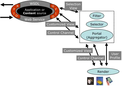
There are several areas where the discussion of sec. 4 is incomplete and here we clarify some user interface issues which we discuss in the context of universal accessibility i.e. ensuring that any Web service can be accessed as well as possible by any user irrespective of their physical capability or their network/client connection. Universal access requires that the user interface be defined intelligently by an interaction between the user “profile” (specifying user and client capabilities and preferences) and the semantics of the Web service [20]. Only the service itself can in general specify the most important parts of its user-facing view and so how the output should be modified for clients of limited capabilities. This implies the modular pipeline of fig. 10 (a) is deficient in the sense there must be a clear flow not only from the “basic Web service” to the user but also back again. This can be quite complicated and it is not clear how this is achieved in general as the pipeline from Web service to the user can include transformations, which are not reversible. We can consider the output of each stage of the Web service as a “document” – each with its own document object model – preferably different instances of the W3C DOM were possible. The final user interface could be a pure audio rendering for a blind user or a bitmap transmitted to a primitive client (perhaps a cell phone) not able to perform full browser functions. Our user facing port must transmit information in a way that user interactions can be properly passed back from the user with the correct semantic meaning. Current browsers and transformation tools (such as XSLT) do not appear to address this. At this stage we must assume that
g directly between user interface and the Web servic general a direct back channel does not appear the usual solution but rather a mix of transport backwards through reversible transformations in the pipeline and direct communication around stages (such as the portal controller) where necessary. In any cases some virtual back channel must exist that translates user interaction into an appropria response by the Web service on the user-facing po
Actually there are really three key user-facing sets of ports a) The main user-facing specification output ports that in
ge
this problem is solved perhaps with a back channel communicatin e. In
te rts.
neral do not deliver the information defining the
h r
b)
t. This in general need not pass through the portal, as this
c)
ache) as part of the “event service” as it rovides a general service (aggregating user interface components) for all applications (Web services). This packaging may not
display but rather a menu that defines many possible views. A selector in fig. 14 combines a user profile from the client (specified on a special profile port) wit this menu to produce the “specification of actual use output” which is used by a portal, which aggregates many user interface components (from different Web services) into a single view. The result of the
transformer may just be a handle, which points to a user facing customized output port.
Customized user-facing output port that delivers the selected view from step a) from the Web service to the clien
User Profile Web Service O
O
Render Portal (Aggregator)
Selector Filter
Control Channel Customized View Control Channel
Customized View Selection
View
Application or
Content source
WSDL
F I R
[image:9.612.62.300.337.512.2]F I U
Fig 14: Architecture of Event Service and Portal to support Universal Access
only needs the specification of the interface and not the data defining the interface. For multi-media content, step a) could involve a choice of codec and step b) the transmission of the chosen codec. The conversion between codecs could in fact involve a general filter capability of the event service as another Web filter service as illustrated in fig. 7. It seems appropriate to consider interactions with user profiles and filters as outside the original Web service as they can be defined as interacting with the message using a general logic valid for many originating Web services.
User-facing input/output port, which is the control channel shown in fig. 14.
Note that in fig.14 we have lumped a portal (such as Jetspeed [21,22] from Ap p
research is needed in areas like the DOM to allow universal interfaces to be generated for general web services. We would like to thank Al Gilman and Greg Vanderheiden from the Wisconsin Trace Center for discussions in this area.
Acknowledgements
ible through partial support provided by DoD High Performance Computing Modernization he This publication made poss
References
1. The Grid Forum http://www.gridforum.org 2. Globus Grid Project http://www.globus.org
3. “Peer-To-Peer: Harnessing the Benefits of a Disruptive Technology”, edited by Andy Oram, O’Reilly Press March 2001. 4. United Kingdom e-Science Activity http://www.escience-grid.org.uk/
5. Hasan Bulut, Geoffrey Fox, Dennis Gannon, Kangseok Kim, Sung-Hoon Ko, Sangmi Lee, Sangyoon Oh, Xi Rao, Shrideep Pallickara, Quinlin Pei, Marlon Pierce, Aleksander Slominski, Ahmet Uyar, Wenjun Wu, Choonhan Youn “An Architecture for e-Science and its Implications” presented at 2002 International Symposium on Performance Evaluation of Computer and Telecommunication Systems (SPECTS 2002) July 17 2002.
http://grids.ucs.indiana.edu/ptliupages/publications/spectsescience.pdf
6. Geoffrey Fox, Ozgur Balsoy, Shrideep Pallickara, Ahmet Uyar, Dennis Gannon, and Aleksander Slominski,
"Community Grids" invited talk at The 2002 International Conference on Computational Science, April 21 -- 24, 2002 Amsterdam, The Netherlands. http://grids.ucs.indiana.edu/ptliupages/publications/iccs.pdf
7. Web Services Description Language(WSDL) version 1.1 http://www.w3.org/TR/wsdl 8. Sun Microsystems JXTA Peer to Peer technology. http://www.jxta.org.
9. W3C Semantic Web http://www.w3.org/2001/sw/
10. XML based messaging and protocol specifications SOAP. http://www.w3.org/2000/xp/. 11. Sun Microsystems. Java Message Service. http://java.sun.com/products/jms.
12. Geoffrey Fox and Shrideep Pallickara “The NaradaBrokering Event Brokering System: Overview and Extensions; proceedings of the 2002 International Conference on Parallel and Distributed Processing Techniques and Applications
(PDPTA'02).
http://grids.ucs.indiana.edu/ptliupages/projects/NaradaBrokering/papers/NaradaBrokeringBrokeringSystem.pdf
13. Geoffrey Fox and Shrideep Pallickara “JMS Compliance in the NaradaBrokering Event Brokering System” to appear in the proceedings of the 2002 International Conference on Internet Computing
(IC-02). http://grids.ucs.indiana.edu/ptliupages/projects/NaradaBrokering/papers/JMSSupportInNaradaBrokering.pdf 14. Geoffrey Fox and Shrideep Pallickara “Support for Peer-to-Peer Interactions in Web Brokering Systems” to appear in
ACM Ubiquity. http://grids.ucs.indiana.edu/ptliupages/projects/NaradaBrokering/papers/P2PSystems.pdf
15. Geoffrey Fox, Sung-Hoon Ko, Marlon Pierce, Ozgur Balsoy, Jake Kim, Sangmi Lee, Kangseok Kim, Sangyoon Oh, Xi Rao, Mustafa Varank, Hasan Bulut, Gurhan Gunduz, Xiaohong Qiu, Shrideep Pallickara, Ahmet Uyar, Choonhan Youn,
Grid Services for Earthquake Science; Concurrency and Computation: Practice and Experience in ACES Special Issue, 14, 371-393, 2002. http://aspen.ucs.indiana.edu/gemmauisummer2001/resources/gemandit7.doc
16. Geoffrey Fox, Wenjun Wu, Ahmet Uyar, Hasan Bulut "A Web Services Framework for Collaboration and
Audio/Videoconferencing"; proceedings of 2002 International Conference on Internet Computing IC'02: Las Vegas, USA, June 24-27, 2002. http://grids.ucs.indiana.edu/ptliupages/publications/avwebserviceapril02.pdf
17. Hasan Bulut, Geoffrey Fox, Shrideep Pallickara,Ahmet Uyar and Wenjun Wu, Integration of NaradaBrokering and Audio/Video Conferencing as a Web Service.
http://grids.ucs.indiana.edu/ptliupages/publications/AVOverNaradaBrokering.pdf
18. Anabas Collaboration Environment, http://www.anabas.com
19. OASIS Web Services for Remote Portals (WSRP) and Web Services for Interactive Applications (WSIA) http://www.oasis-open.org/committees/
20. Geoffrey Fox, Sung-Hoon Ko, Kangseok Kim, Sangyoon Oh, Sangmi Lee, "Integration of Hand-Held Devices into Collaborative Environments"; proceedings of the 2002 International Conference on Internet Computing (IC-02). June 24-27 Las Vegas. http://grids.ucs.indiana.edu/ptliupages/publications/pdagarnetv1.pdf.
21. Jetspeed Portal from Apache http://jakarta.apache.org/jetspeed/site/index.html
22. O. Balsoy, M. S. Aktas, G. Aydin, M. N. Aysan, C. Ikibas, A. Kaplan, J. Kim, M. E. Pierce, A. E. Topcu, B. Yildiz, and G. C. Fox., "The Online Knowledge Center: Building a Component Based Portal." Proceedings of the International Conference on Information and Knowledge Engineering, 2002.