International Journal of Innovative Technology and Exploring Engineering (IJITEE) ISSN: 2278-3075, Volume-8 Issue-12, October 2019
Abstract: Reverse engineering plays a significant role in rebuilding of a product. This suggests a situation arranged for reverse engineering of turbine blade used in aero engine components. It is the process that designs by using point cloud data to get CAD models. Reverse Engineering is a method for creating CAD model of physical parts whose designs are not available or fractured or damaged parts by digitizing a persisting prototype, reverse engineering creates a computer model by applying 3D scanning. In this paper it is for reproducing the geometries of aero engine physical components i.e. turbine blade in digitizing process through 3D Scanning and CMM Inspection. Complete transformation of physical data into CAD models by applying modern measuring machines and with its integrated software (Creo 2.0) extraction of information about geometry to develop the part models. CMM inspection & reverse engineering software be located active to evaluate any dimension deformation. The deviation in the dimension is taken into attention as evaluating characteristics. The error analysis of some features between 3D scan data, CMM, CAD model and MESH data are performed.
The deviation between scan data, CAD model & CMM are within the suitable limits and deformation between CAD model & MESH data are within -0.1 to +0.1mm. The CAD model generated is within suitable criteria i.e., 30 microns. Parts which require to reverse engineered. After completion of the CAD model 3D printing development is done.
Keywords: Reverse Engineering, 3D scanning, point Cloud Data, CAD Software, 3D printing.
I.INTRODUCTION
R
everse engineering stands in the universal name of digital technology of CAD model, rebuilding knowledge of geometric model and manufacturing technology, which is different from the formation of traditional geometric model. In real-world application of the industrial area, reverse engineering includes the design of new parts, replication of existing parts, renovation of damaged or worn parts, improving the accuracy of the model and discovery of digital model. Reverse engineering is showed from the real object, which is diverse from overall design and manufacturing process. Figure 1 which is shown below is the basic flow chart of reverse engineering. In the flow chart it‟s clearly revealed that given physical model is digitized with several dataRevised Manuscript Received on October 05, 2019. * Correspondence Author
Madhigani Sneha, PG Scholar,department of mechanical engineering, Vidya Jyothi Institute of Technology, Hyderabad, India. Email: [email protected]
G. Sreram Reddy, Department of Mechanical Engineering, Vidya Jyothi Institute of Technology, Hyderabad, India. Email: [email protected]
Dr. L. Madan Ananda Kumar Department of Mechanical Engineering, Vidya Jyothi Institute of Technology, Hyderabad, India. Email: [email protected]
collection techniques (contact and non-contact) then data is processed for 3D scanning.
Fig. 1. Basic flow of reverse engineering Reverse engineering process involves of three phases, namely scanning, which is done on contact or non-contact scanners. The second phase is point processing, this process involves collecting point cloud data and converted to STL/Mesh file. This phase also allows user to join multiple scans of the part. Generation of CAD model from the point cloud data is the most complex phase in reverse engineering technology. The output of this phase is geometric model of the finished product
.
In this paper we generally deal with the turbine blade. A typical reverse engineering process always starts through measuring actions on a sample part. But in this case (turbine blade), selection of a effective part to start by is very difficult. Turbine blades are generally made by investment casting. A turbine blade is the discrete component which makes up the turbine unit of a gas turbine or steam turbine. The blades are responsible for removing energy from the high temperature, high pressure gas formed by the combustor.
Turbine blades are too expensive parts. Nobody throws them away till all the possible refurbishment activities must remained examined.
Even if refurbishment concerns fail to patch-up the blades, most of the companies would rather in its place of throwing them away-store them and wait for
the probable future enhancements
Reverse Engineering on Jet Engine Turbine
Blade Based on 3D Printing Design Intent
of refurbishment technologies. This technique of transfer the blades to the turbine disc is of significant, since the stress in the disc about fixing or in the blade root has a vital bearing on limiting rim speed. Several approaches of blade attachment are
Fir tree Root (with locking plate). Fir tree Root (with shank seals).
De Laval By it Root (with locking screw). B.M.W.hollow blade (with retaining pins).
Many of these days the gas turbine use fir tree root type attaching method where to decrease the loss of effectiveness owed to gas leakage, through the blade tips. A shroud is frequently fitted which is formed by forging minor segment at the tip of each blade, so that when all the blades are fitted to the disc, the section form an outer ring everywhere to the blade tips.
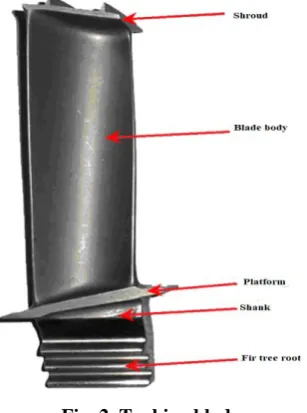
[image:2.595.98.252.350.557.2]In this research we have taken a damaged part of turbine blade. The physical object of this damaged part has taken into consistency and reverse engineering process is done. Primarily in this process we have opted with 3D scanning of components and conversion of CAD model and following with that CMM inspection of components. This both approached method results are used for cross check 3D CAD models.
Fig. 2. Turbine blade
Lee et.al. (1998) [3] estimated a novel technique that integrates procedure of reverse engineering and rapid prototyping technology. Feng et al. (2001) [6] presented the result of scan depth and projected range on the digitizing accuracy of a laser/ CMM scanning system. Speck noise in the CCD laser pictures was taken as the main source of arbitrary error. A bilinear practical model taken and recognized which was gifted to existing estimates of the reasonable error which was less than 25 micros variations. Chen et.al. [11] Is mainly about innovative methods of digitizing and exhibiting of freeform surfaces and practices a turbine airfoil as a circumstance training to verify its capability. It shows a way to reach digitizing and showing activities, then nearby there is no condition to design aspects or shape constraints and symmetries of turbine blades. According to Fisher [9], it matters that human ideas are not arbitrary; the shapes of most ordinary objects follow standard resolutions rising from
custom, utility or engineering design, so this is a knowledge-based approach. It sustains that manipulating this additional information allows better-quality reverse engineering. His method is again dropping a report that involves of two terms: the first term is a least square fitting term that guarantees that the model surfaces unqualified close to the image data; the second term translates the penalties designed for constraint violations.
Tai and Huang [8] stated the situation of design intent through reverse engineering. They deliberate that the best method to get high-quality curve suitable of a B-spline on restrained data is to use data points that have been segmented physically by the engineer translation to the design intent. The work mostly thinks on how to operate the measured points to make them for a effective B-spline suitable for and contracts with algorithms for noise decrease and the regeneration of absent points in demand to get a flatter B-spline. It comprises some universal useful hints, but does not display really how to contract with design aspects of a part. Várady T, Martin RR [1] a wider explanation of the term “reverse engineering” strength perhaps contain assuming the concentrating of the innovative designer to some degree. M.Bici et al. [2] projected an innovative reverse engineering procedure that is being recognized to realize the complete automation of the review process original from the design necessities (dimensional and geometrical tolerances) as they normally appear in the module‟s official drawings. Jacek Rysinski et al. [7] labeled an request of a three-dimensional scanner for construction a special analytical stand and deliberated an new method of discovery of physical defects for estimating mainly the measurements of the pitting holes.
Thompson et al. [10] defined a model of a reverse engineering system that practices geometric primitives. The main benefit of these feature-based methods is the ability of creating highly precise models, even when the 3D point data has significant errors. This is due to the circumstance that particular geometric primitives are identified to the system. So, after knowing a known feature, there is no essential to go for higher precisions. The primitives identified to this sort of software are partial to quadric features such as even surfaces, cylinders, etc. So this system is by no resources capable of identifying free-form surfaces like airfoils. Bardell et.al. (2003) [5] has consumed likely for projecting process of automating the conformed of an satisfactory free-form surface, by resources of Coordinate Measuring Machine.
Computer-aided geometric design be located used to estimate the surface for optimal continuity and measured CMM data accurateness. A.Gameros et al. [4] offered a reverse engineering (RE) process by means of an optical scanner and X-ray computed tomography (CT) apparatus for freeform surfaces,
created on a case study of a turbine blade made of Inconel, comprising the renewal of its internal cooling system and exposed that the reverse engineering procedure offered is promising when connecting uncertainty values against common industrial tolerances. Xie et.al. (2005) [12] had proposed a multi-probe
International Journal of Innovative Technology and Exploring Engineering (IJITEE) ISSN: 2278-3075, Volume-8 Issue-12, October 2019
with a CMM, structured-light sensor, trigger probe and rotary table. Two types of scanning approach which was multitier scanning approach method and rotating scanning method had been used. (Chung and Liao, 2001).Bhupender Singh et. Al. (2011) [13] resists the solid modeling and finite element training of crane boom via PRO/E and ALTAR HYPER MESH with optistruct 8.0 Software to get the deviations of stress and movement amongst diversity of parts of the crane boom and reasonable actions were occupied to retain away from the high stress level and displacement. The solid model remained produced using PRO/E Wildfire 2.0 using assumed dimensions. The solid model was relocated to ALTAR HYPER MESH and investigation of the model remained approved out in optistruct solver 8.0 over given constraints. The burden standards designed the three end points which originate to be underneath the limits of ultimate tensile strength and yield strength of boom material. So it can be said that under the given situation of boom physical and load carrying size, crane boom was safe hands to high the load up to 12 Ton.
II.EXPERIMENTATION A.Methodology
In this relative work Turbine blade of a jet engine is made by using revere engineering process. The scanning is done by the scanners having white light phenomenon and dual camera technology. With the white light phenomenon, the point cloud data is acquired through focusing the white light on the aero engine component & dual camera technology and conversion of scan data into CAD model by following CMM inspection and by inspecting the CAD model by using reverse engineering software‟s. This both approached methods results are used for cross check 3D CAD model.
B.Experimental Work
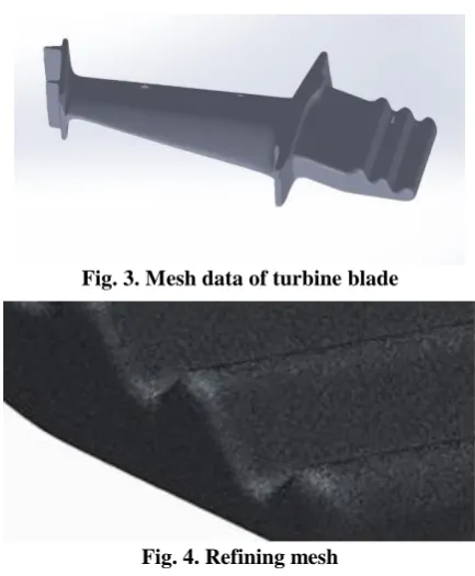
3D Scanning: We have used EviXscan 3D Pro scanner with white light source for digitize physical components as virtual mesh data with precision of 13 µm which is shown in figure 3. Later on with the help of software application, post processing for scan data was completed by patching and refining mesh and point cloud data is shown in figure 4. Then mesh data is converted into solid and surface models by using software application for creating sectional curves and basic geometrical feature. The tool extracts the data with 4 – 10 µm deviation from scan data.
Table- I:Specification of EviX Scan 3D pro Scanner Technical Specification Evixscant3Dtpro
Light source type white
Number and type of cameras
2x5mpix
Scanning time 4sec
Measuring range Larget430x330x110mm Ambient temperature +10ºcttot+30ºc
[image:3.595.317.534.44.307.2]Storage temperature From-20ºcttot40ºc
Fig. 3. Mesh data of turbine blade
Fig. 4. Refining mesh
[image:3.595.360.515.384.469.2]CAD Modeling: Preprocessed and aligned surface models of scan data are converted into solid featured CAD models by Creo 2.0 version software. Complete extraction of geometrical features from IGES files (scan surface models) to regeneration of virtual model with categorized feature tree.
Fig. 5. Creating sectional curves
[image:3.595.332.483.582.666.2]CMM Inspection: After completion of CAD modeling of components, we have gone with CMM inspection to evaluate any deviations between 3D scan data and CAD models. The job was done on Nikon Altera + CMM platform with accuracy of 1.5 µm with 1 mm probe head. Some crucial geometrical values to cross check with CAD dimensions
Fig. 6. Replicating surfaces
3D Printing: After completion of CMM inspection and finding the errors in the turbine blade then 3D printing process is done. The 3D printing procedure mostly forms a three-dimensional object from a
model, generally by applying adding material layer by layer, so that the object is formed. Depending on the component the printing process takes time such that the turbine blade has took around 3hours 19min.
Table- II: Deviation on the turbine blade 1 Part
Feature 3D Scan Model
CMM CAD
Model
Scan – CAD Deviation
CMM - CAD Deviation Tip
thickness
15.392 15.461 15.39 -0.002 -0.071
Tip width 16.96 17.099 16.96 0 -0.139
Root thickness
11.88 11.855 11.884 0.004 0.029
Root width
36.672 36.587 36.669 -0.003 0.082
Root wall thickness
22.382 22.604 22.38 -0.002 -0.224
III.RESULTA NDDISCUSSION
Deviations in the dimensions are taken into consideration as evaluating characteristics. Here are the error analysis of some of features between 3D scan data,
CMM, CAD models and mesh data. The deviations of turbine blade as shown in the table 2 & 3.
The mesh data and CAD model of turbine blade is given as shown in the figure 8 & 9. When both the data files are compared with revrse engineering software the deviations are formed within the tolerance limits ±0.1 and the comparision between three result data is given in the table IV. Root mean square, variation and standard deviation are given by the values of 0.057, 0.0032 &0.0568.
Fig. 8. Mesh data of turbine blade
Fig. 7. 3D Printing of turbine blade
Table-III:: Deviation on the turbine blade 2
Part Feature 3D Scan
Model
CMM CAD
Model
Scan – CAD Deviation
CMM - CAD Deviation
Tip thickness 14.368 14.272 14.356 -0.012 0.084
Tip width 16.121 15.9 16.11 -0.011 0.21
Root thickness 12.02 12.708 12.101 0.081 -0.607
Root width 36.645 36.814 36.625 -0.02 -0.189
Root wall thickness 22.152 22.509 22.156 0.004 -0.353
Table- IV: overall values
Name 3D compare
Min. -0.2582
Max. 0.2582
AVG. -0.0048
RMS 0.057
Std. Dev. 0.0568
Var. 0.0032
+Avg. 0.0336
-Avg. -0.0414
In Tol. (%) 91.2141
Out Tol. (%) 8.7859
Over Tol. (%) 3.7056
[image:4.595.31.298.102.260.2]Under Tol. (%) 5.0803
[image:4.595.76.503.441.779.2]International Journal of Innovative Technology and Exploring Engineering (IJITEE) ISSN: 2278-3075, Volume-8 Issue-12, October 2019
Author-1 Photo
Author-2 Photo
Author-3 Photo
Name Tolerance Gap Distance
Reference points Measured points
x y z X y Z
1 ±0.1 0.1328 -5.9988 -1.9068 8 -6.079 -2.0126 7.9987
2 ±0.1 -0.046 1.9997 -1.7717 21.9999 1.9796 -1.7304 21.9963
[image:5.595.63.518.46.722.2]3 ±0.1 -0.0982 -2.0003 -2.324 33.9999 -2.0246 -2.2291 33.9939
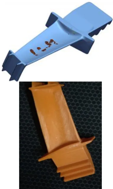
Fig. 9. CAD model of turbine blade
Fig. 10. 3D compare
Fig. 11. Comparing CAD and mesh data of turbine blade
IV. CONCLUSION
This case study has allowed us to learn how the reverse engineering can be useful for CAD model generation. Already existing parts are manufactured for aero engine components such as, turbine blade. In this paper it shows how a 3D scanner works for turbine blade and its presentations in the reverse engineering and how to get the required data from the object
with the scanner. Also different software‟s are used to create the point cloud data and mesh to orientate it and define the position of the mesh. Creo is used for creating CAD model of the compound aero component by drawing the different surfaces by using mesh file, points and coordinates are produced. CMM inspection is employed to evaluate any deviations between 3D scan data and CAD model. The accuracy of the measurements is within the permissible limits and further the CAD model can be used for manufacturing. Then 3D printing process is done.
REFERENCES
1. T. Várady, R.R. Martin, J. Cox, Reverse engineering of geometric models, Computer-aided design 29, 4(1997) 255-268.
2. L. Li. N. Schemenauer, X. peng, Y. Zeng, P.Gu, A reverse engineering system for rapid manufacturing of complex objects, Robotics and Computer-Integrated Manufacturing. 18.1. (2002) 53.
3. Technological documentation of ATOS GOM II optical scanner, Braunschweig, Germany GOM, 2007.
4. 3D scanning gallery for industrial applications 3D solutions available at: www.3D solutions.com [22.5.2013].
5. Brajlih, T. Tasic, T. Drstvensek I. Valentan B. Pogacar, V. Balic, J.Acko, possibilities of using 3D optical scanning in complex geometrical inspection. Strojniski vestnik-journal of mechanical engineering, volume 57, 11, (2011)826-833.
6. Chase, K W and Greenwood, W H „Design issues in mechanical tolerance analyses‟, ASME Manufacturing Rev., volume I No. I (1988) pp. 50-59.
7. Fu, P. (2008). In reverse engineering an industry perspective, Springer, ed V, Raja and K J Fernandez. 177-193 Berlin.
8. Tai CC, Huang MC(2000) the processing of data points created on design intent in reverse engineering. International journal of machine tool manufacturing 40:1913-1927.
9. Fisher RB (2004) Applying information to reverse engineering problems. Computer-Aided design 36501-510.
10. Thompson WB, Owen JC (1999) Feature-based reverses engineering of mechanical portions. IEEE T robotic automation 15(1):120-125
AUTHORS PROFILE
Madhigani Sneha pursuing Mtech(cad/cam) department of mechanical engineeringofile Vidya Jyothi Institute of Technology, Hyderabad, India. Email:
Dr G Sreeram Reddy, awarded with PhD degree from JNTUH in the area of Reverse Engineering with more than 25 publications. He is member of ISTE and IWE.