REFLECTION COEFFICIENTS FOR DEFECTIVE DIFFUSION BONDS
INTRODUCTION
James H. Rose Ames Laboratory Iowa State University Ames, IA 50011
The quality of diffusion bonds can, to some degree, be characterized using ultrasonic probes. Consequently, considerable effort has gone into the development of theories that predict the ultrasonic scattering from defective bonds. There are three major lines of development. First Baik and Thompson [1] and Angel and Achenbach [2] have examined the low
frequency limit; they have described the elastic scattering by an "effective" spring-model in this regime. Second Sotiropolous and Achenbach [3,4] have developed a rigorous approach that is valid at all frequencies for the case of microcracks at the bondplane; the crucial theoretical tool in this case is the crack opening displacement. Their work is, however, restricted to the case of normally incident plane waves. Rose [5] presented an approximate method, the single scattering approximation, for computing the reflection coefficients at normal
incidence; it is based on using the scattering amplitudes for the various defects at the bondplane.
In this paper, the relation of the reflection coefficient to the scattering amplitude is further examined. Our major result is a general, exact expression for the reflection coefficient for an arbitrary angle of incidence; it is written down in terms of certain generalized scattering amplitudes that we define below. We then show that the single scattering approach follows as an elementary approximation to this general
expression. Experimental tests of the single scattering approximation can be found in the companion paper "Experimental Studies Pertaining to the Interaction of Ultrasound with Metal-Metal Bonds" by Margetan et.al., which also appears in these procedings.
THEORETICAL DEVELOPMENT
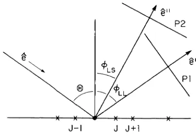
The bondplane is chosen to lie in the xy-plane. To each flaw, J, we assign a centroid that lies in the xy-plane. We locate this centroid by the position vector, RJ. The scattering geometry is shown in Fig. (1). We imagine a plane wave displacement field that is incident in the direction denoted by the unit vector,
e.
This incident field interacts with the flaws and scatters in all directions. In most directions the scattered fields from the various defects interfere destructively; in this case the scattering is weak and is said to be diffuse. In two special directions, the scattered fields can add up constructively; these are the directions of specular reflection. One direction corresponds to a reflected longitudinal wave and the other to a reflected transverse wave. In Fig. (1), we denote these directions of specular reflection bythe unit vectors,
e'
ande".
Also shown in the figure are two planes Pl and P2, which lie normal to the directions of specular reflection. These planes are parallel to the reflected plane waves.Our calculation proceeds by computing the displacement field for a distribution of scatterers and then averaging that displacement field over the planes Pl and P2. The result of the average is the coherent
(specular) part of the wavefield. There are some subtleties in the calculation; these result from the fact that the bondplane is infinitely extended in two dimensions. We account for these subtleties by a series of limiting procedures for calculating the displacement field. We imagine that all the defects lie in a large circle in the bondplane. Outside this circle the bond is perfect. The displacement field generated by this collection of flaws can be calculated from ordinary elastic wave scattering theory [6]. The resulting displacement field is then averaged over the planes Pl and P2. This average is obtained by taking the far-field asympototics of the displacement field and using a stationary phase (asymptotic in distance) argument to compute the average over the planes. The important thing is that we first take the incident plane wave to be infinite, then we take the radius of the circle that contains the flaws to go to infinity, and finally we allow the planes Pl and P2 to recede infinitely far from the origin of coordinates.
The derivation to be described could be carried out using either a volume or a surface formulation of scattering theory. In this paper, we present our results in the language of the volume formulation. The same results would be obtained if the surface formulation of scattering were employed. We denote the elastic constants of the uniform and isotropic host space by c•,ikl and the density by p". The elastic constants and density of the inclusion may be spatially varying and are denoted by cljklcX:) and 6p(X:).
J-1 J J+l
[image:2.482.145.338.462.598.2]The displacement field, Ui, is determined by the elastodynamic wave equation
(l) and its boundary conditions. Here, uu denotes the angular frequency. Tensor notation will be used. Eq. (1), together with radiation boundary conditions, can be rewritten as an integral equation
u
i<
x)
=u
i 0c
x)
+ w 2j
d 3x
·
o
Pc
x
·)
g imc
x
-
x')
u
mc
x
·)
Here U1° is the incident, plane-wave displacement field, while lip- p- p o
and lie,,.,=
c,,.,- co,,.,.
The function gim in Eq. (2) denotes the(2)
elastodynamic Green's function; the explicit form of gim is given in Ref. (6). The incident displacement field is given by
(3)
Here, the velocity, c, is equal to CL for longitudinal waves and to CT for transverse waves. The unit polarization vector is denoted by p.
The scattered displacement field can be partitioned into
contributions from the individual scatterers. In order to illustrate this, we note that Bp and
oc,,.,
are non- zero only inside the flaws. Hence the integration in Eq. (2) reduces to a sum of integrations; eachintegration is over the volume of a particular flaw. If we define the scatterer's field as U" U-u·, Eq. (2) can be rewritten as
u~c
'
LJ U J ~c+
f
d3x'6CiklmGii.kUl.m· VJHere the integrals are over the volume VJ of the Jth flaw.
For a point,
r,
that is distant from the bondplane we can use the far-field expansion for the Green's function. For the J1h flow this expansion is taken about the centroid,RJ.
We obtain a simplified expression for the scatt.ered field,J U; sc (w,e,p,r) ;.. - ~
=
(4)
(5)
the scattering direction is defined bye,= (X-R1)1Jx-R1J. Finally p
denotes the direction of polarization of the incident wave. The functions Jci and Joi are generalized scattering amplitudes and are defined as follows. For the Jth flaw we translate the coordinate system so that the origin of coordinates falls at the centroid
R
1 • Next, definethe generalized scattering vector, Jgi, by
(6)
Here y represents the wave vector of the wave that is scattered in the
x-direction; it is
<i-
wxlcL for longitudinal waves and it isP-
wxlcrfor transverse waves, Finally,
J gJa), - (7 a)
and
(7b)
The generalized scattering amplitudes give the far-field scattering pattern for the Jth flaw. These amplitudes are normalized by placing the particular flaw considered at the origin of coordinates. It is this shifting of the origin in the definition of Jc and Jo that gives rise to the plane-wave prefactor in Eq. (5). We note that Jc and Jn contain all the effects of multiple scattering and flaw-flaw interactions. Formally, this is accounted for by noting that the field Uj, which appears in the definition of the generalized amplitudes (Eqs. 6-7), is the total
displacement field and is determined by the self-consistent scattering of all the defects. Finally we note Jc and Jn reduce to the ordinary
elastic wave scattering amplitudes if all the flaws are absent except for the J th flaw.
Specular reflection coefficients will now be inferred from the generalized scattering amplitudes. We proceed by averaging the
scattering of the Jth flaw over a plane that is distant from the Jth flaw but otherwise arbitrary. Since the plane is distant from the scatterer,
the displacement field on the plane can be represented in terms of Jci and Jni. Next we sum the average fields of all the flaws on this plane. For planes Pl and P2 that are normal to the specular directions e' and
e , the resulting sum adds coherently. For these planes one obtains averages of the displacement field that have the form
Here Ri is the desired reflection coefficient.
REFLECTION COEFFICIENTS
(8)
The reflection coefficients are obtained by summing the
contributions of all the scatterers to the average displacement on the planes Pl and P2. The details of the summation are slightly involved and will be presented in a longer paper. Suffice it to say that the
summation involves an asymptotic integration of the phase function
exp(ia I
x-
R
1 J) over Pl and P2; these planes are assumed to be far from theThe reflection coeff
L-+LR ;(W, e')
L-+TR ;(W, e")
T-+LR,(w,e',p)
and
.ients are given by
-2nnC,(w,e',e,p=e) iacos<PLL
-2nnD,(w,e" ,e,p=e) i
f3
COS <jl LT-2nnC,(w,e',e,p) iacos<PTL
-2nnD;(w,e",e,p)
if3
COS <l>TTHere the symbols
c,
andD,
refer to average values of the generalized scattering amplitudes. For example,(9a)
(9b)
(9c)
(9d)
(10)
and similarly for Di. The angles tPLL•tPLT•tPTL and <I>TT are given by Snell's law. Namely tPLL = <l>n =
e,
while <I>LT and <I>TL depend on the ratio of velocitiesVTIVL in the ordinary way. Finally, the T ~ T and T ~ L reflection
coefficients depend on the direction of polarization,
p,
of the incident wave.The reflection coefficients are given in vector form. To obtain a final result, it is necessary to contract Ri with a unit vector
describing the polarization of the outgoing wave. For example, if the outgoing wave has longitudinal polarization, one contracts Ri withe,·, i ·e. R 1
e
1'. For outgoing T-waves, the reflection coefficients arecontracted with a polarization vector that lies normal to the propagation direction.
APPROXIMATE EVALUATION
Exact evaluation of Eq. (9) for the reflection coefficients is intractable. This intractability arises since
C,
andD,
involve the total wavefields (including all multiple scattering terms). Knowledge of the total wavefield is not available, nor can such knowledge bestraightforwardly obtained. Hence, the need for approximation arises. The single scattering approximation has been used to evaluate the reflection coefficients [5]. In this approximation we assume that each flaw scatters independently. That is, we compute the scattering amplitude for the Jth flaw as if it were a single flaw in an otherwise defect-free, uniform and homogeneous space. The resulting far-field displacement fields are described by the ordinary longitudinal scattering amplitude, Ai, and the transverse scattering amplitude, Bi. The single scattering approximation is to replace Ci by Ai and Di by Bi.
The major utility of the single scattering approximation arises in the problem of bond characterization. This utility arises because it describes the frequency dependence of the reflection. In particular, the single scattering approximation accurately predicts the location of the peak in the reflection coefficient for low area fractions of flaws. The position of the peak combined with the low frequency part of the signal combine to yield an estimate of the flaw size and the area fraction of defects if the flaw type is known ahead of time. Fortunately, most bond quality problems due to discrete flaws such as disbands fall into the low area fraction limit (otherwise, the ultrasonic reflection would be very high and the bond would be obviously unfit). The single scattering approximation has been compared to the experimental reflection coefficients obtained from several special laboratory samples.
Generally, the agreement between theory and experiment is encouraging. Peak locations were accurately predicted; however, peak heights were less accurate reproduced. The comparison of theory and experiment is
discussed in detail in a paper by Margetan et. al. in these proceedings.
ACKNOWLEDGEMENT
This work was sponsored by the Center for Advanced Nondestructive Evaluation, operated by the Ames Laboratory, USDOE, for the Air Force Wright Aeronautical Laboratories/Materials Laboratory under Contract No. W-7405-Eng-82 with Iowa State University.
REFERENCES
1. J.-M. Baik and R. B. Thompson, J. Nondes. Eval. ~. 188 (1984). 2. Y. C. Angel and J. D. Achenbach, Wave Motion,
1.
375 (1985).3. D. A. Sotiropolous and J. D. Achenbach, J. Acoust. Soc. Am. 84, 752 (1988).
4. D. A. Sotiropolous and J. D. Achenbach, J. Nondes. Eval.
1.
123 (1988).5. J. H. Rose, "Ultrasonic Reflectivity of Diffusion Bonds", in Rev. of Progress in QNDE, 8B, 1925 (1988).