1
A Beaconless Asymmetric Energy-Efficient Time Synchronization
Scheme for Resource-Constrained Multi-Hop Wireless Sensor Networks
Xintao Huan, Kyeong Soo Kim,
Senior Member, IEEE
, Sanghyuk Lee, Eng Gee Lim,
Senior Member, IEEE
, and
Alan Marshall,
Senior Member, IEEE
Abstract—The ever-increasing number of WSN deployments based on a large number of battery-powered, low-cost sensor nodes, which are limited in their computing and power resources, puts the focus of WSN time synchronization research on three major aspects, i.e., accuracy, energy consumption and computa-tional complexity. In the literature, the latter two aspects haven’t received much attention compared to the accuracy of WSN time synchronization. Especially in multi-hop WSNs, intermediate gateway nodes are overloaded with tasks for not only relaying messages but also a variety of computations for their offspring nodes as well as themselves. Therefore, not only minimizing the energy consumption but also lowering the computational com-plexity while maintaining the synchronization accuracy is crucial to the design of time synchronization schemes for resource-constrained sensor nodes. In this paper, focusing on the three aspects of WSN time synchronization, we introduce a frame-work of reverse asymmetric time synchronization for resource-constrained multi-hop WSNs and propose a beaconless energy-efficient time synchronization scheme based on reverse one-way message dissemination. Experimental results with a WSN testbed based on TelosB motes running TinyOS demonstrate that the proposed scheme conserves up to 95% energy consumption compared to the flooding time synchronization protocol while achieving microsecond-level synchronization accuracy.
Index Terms—Beaconless time synchronization, energy effi-ciency, reverse asymmetric time synchronization, wireless sensor networks.
I. INTRODUCTION
T
IME synchronization for wireless sensor networks (WSNs) has been extensively studied in the last decades as the number of WSN deployments has been gradually increasing over the period [1]–[3].Because many existing time synchronization schemes rely on sensor nodes’ broadcasting synchronization messages re-ceived from a root node (i.e., flooding) to achieve network-level time synchronization (e.g., [4], [5]), additional compu-tation and energy consumption are imposed on the resource-constrained sensor nodes which are already loaded with tasks including medium access control (MAC) protocol, message scheduling and routing, and data measurement. The Flood-ing Time Synchronization Protocol (FTSP) [4], which is a benchmark among WSN time synchronization schemes, is a typical example of flooding-based time synchronization schemes, where the energy consumption caused by the layer-by-layer broadcasting and the computational complexity of estimating the clock skew and offset could be high for battery-powered, low-cost sensor nodes.
To address the high computational complexity of esti-mating the clock skew and offset to achieve microsecond-level accuracy in FTSP, the Ratio-based time Synchronization
Protocol (RSP) has been proposed based on the periodical one-way synchronization message dissemination and a lightweight procedure for the estimation of clock parameters [6]. In RSP, additional thresholds and procedures are introduced to reduce the impact on the clock parameter estimation of the numer-ical errors by the limited floating-point precision (i.e., 32-bit floating-point numbers) of the resource-constrained sensor nodes. However, like FTSP, RSP also relies on the periodical broadcasting of the synchronization messages and, therefore, is not energy efficient in terms of message transmissions by sensor nodes. Another well-known WSN time synchronization scheme is the Timing-sync Protocol for Sensor Networks (TPSN) [7], which is based on the two-way message exchange requiring additional response message along with the beacon message. Considering that the schemes based on the two-way message exchange could achieve higher accuracy in principle by compensating for propagation delay, however, TPSN’s synchronization error of tens of microseconds is quite high even compared to that of the schemes based on one-way message dissemination. In case of the Reference Broadcast Synchronization (RBS) [8], because it requires not only addi-tional reference nodes to broadcast the common clock time but also additional message exchanges between the sensor nodes to estimate their relative time differences, it is also not energy-efficient and proper for resource-constrained sensor nodes. Aiming at conserving the energy consumption through reduc-ing message transmissions for the synchronization procedures, the authors of [9] proposed the Energy-Efficient and rapid Time Synchronization (EETS). Although EETS could reduce the message transmissions between neighboring levels in a hierarchical network, it still strongly relies on the broadcasting of the synchronization messages to achieve network-level time synchronization. Also, because the energy efficiency of EETS is indirectly evaluated through the number of message transmissions using simulations, its actual energy consumption could be different on real sensor nodes.
The authors of [10] proposed a novel energy-efficient time synchronization scheme based on the reverse two-way mes-sage exchange and demonstrated through simulation exper-iments that sub-microsecond-level synchronization accuracy could be achieved. Still, the computational precision required by their scheme (i.e., the precise division of the floating-point numbers) is beyond the capability of most resource-constrained sensor nodes equipped with a low-cost Micro-Controller Unit (MCU) providing only 32-bit floating-point as discovered in [11]. The idea of the reverse two-way message exchange together with message bundling for synchronization and measurement data, however, could be applied for de-signing more advanced energy-efficient time synchronization
2
Head
Measurement Data
T1
T2 Report/ Response
Reverse Two-Way
Message Exchange
Sensor Node
T1
T2 T3
T4 Beacon/
Request
Report/ Response
Data Flow
Two-Way Message Exchange
Sensor Node T1 T4
Report/ Response
Data Flow
T2
Reverse One-Way
Message Dissemination One-Way
Message Dissemination
Measurement Data Estimation Procedures
Estimation Procedures
Estimation Procedures
Estimation Procedures Beacon/
Request
Measurement Data
Data Flows Beacon/ Request
Measurement Data Data Flows
…
…
…
…
Sensor Node
Head
Sensor Node
(a) (b)
[image:2.612.50.301.54.147.2](a) (b)
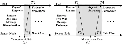
Fig. 1. Overview of the proposed reverse asymmetric time synchronization based on (a) one-way message dissemination and (b) two-way message exchange with optional bundling of measurement data.
schemes targeting resource-constrained sensor nodes because it can greatly reduce the number of message transmissions by sensor nodes.
In this paper, we present the reverse asymmetric time syn-chronization framework illustrated in Fig. 1 and propose the Beaconless Asymmetric energy-efficient Time Synchroniza-tion (BATS) scheme specifically based on the reverse one-way message dissemination shown in Fig. 1 (a). In the proposed framework, all the synchronization procedures are moved from sensor nodes to the head1 as in [11], and application messages (e.g., for reporting measurement data to the head) carry synchronization-related data as well. In addition, BATS does not rely on the “Beacon/Request” messages as shown in Fig. 1 (a), thereby saving energy for their transmissions and receptions at sensor nodes, the latter of which often consume more energy [12]. The proposed scheme is designed to address the three major challenges in WSN time synchronization on resource-constrained sensor nodes, i.e., achieving high synchronization accuracy, reducing energy consumption [13] and lowering computational complexity [14].
Based on the reverse asymmetric time synchronization framework and the one-way message dissemination, the pro-posed BATS scheme combines in a unique way the advantages of several existing WSN time synchronization schemes: Being based on the one-way message dissemination, BATS can take the advantage of simpler implementation compared to those based on the two-way message exchange. Unlike the conventional schemes based on the one-way message dissemi-nation including FTSP, however, BATS is optimized for energy efficiency by reversing the flow of synchronization messages from “head→sensor nodes” to “sensor nodes→head”, which is the key idea of the reverse asymmetric time synchroniza-tion framework. The reverse asymmetric time synchronizasynchroniza-tion framework, on the other hand, is a generalization of the schemes we have proposed in [10] and [11] and belongs to a broader category of reactive time synchronization proto-cols [15], where sensor nodes’ local clocks, which are not synchronized to a common reference, are used to timestamp events; synchronization takes place after the event has been detected. However, BATS is also different from the existing reactive time synchronization protocols like Routing Integrated Time Synchronization protocol (RITS) [5] in its multi-hop
1The head node and the monitoring station (i.e., a PC or a workstation
for data processing) connected to it locally or remotely over the Internet are collectively called the head in this paper.
extension, where, unlike RITS, there is no layer-by-layer time translation at gateway nodes along a multi-hop path; instead, the said time translation is completely moved to the head to relieve the burden of the gateway nodes.
Note that the actual energy consumption and synchroniza-tion accuracy of the proposed scheme are evaluated and analyzed through experiments on a real WSN testbed in this paper. To the best of our knowledge, this is the first work that shows the actual performance of energy-efficiency of the high-precision time synchronization schemes on resource-constrained sensor nodes through real experiments.
The rest of the paper is organized as follows: In Section II, the related work including the time synchronization scheme proposed in [10] based on reverse two-way message exchange and the conventional time synchronization schemes based on one-way message dissemination is discussed. Section III presents the proposed BATS scheme based on the reverse one-way message dissemination. Section IV discusses the multi-hop extension of BATS scheme with a focus on the issue of communication overhead. The results of the performance evaluation of BATS scheme in terms of energy consumption and synchronization accuracy on a real testbed are presented in Section V. Section VI concludes our work in this paper and highlights the future work.
II. RELATEDWORK
A. Time Synchronization Based on Reverse Two-Way Message Exchange
Aiming at providing high-precision time synchronization for an asymmetric WSN with a head equipped with abun-dant computing and power resources and multiple resource-constrained sensor nodes (e.g., powered by standalone bat-teries and equipped with low-cost MCUs), the authors of [10] proposed an energy-efficient time synchronization scheme based on the asynchronous source clock frequency recovery (SCFR) and the reverse two-way message exchange shown in Fig. 1 (b), which we call it EE-ASCFR in short from now on. In EE-ASCFR, the estimation of the clock offset and frequency ratio is separated into the head and the sensor node to reduce the computational complexity of the latter where a logical clock is maintained based on the estimated clock frequency ratio. Although the broadcasting of the beacon messages is still required, the number of message transmissions at sensor nodes is reduced through bundling several measurement data together with synchronization data in a “Report/Response” message. Compared to BATS, parts of the time synchroniza-tion procedures—i.e., the estimasynchroniza-tion of the clock frequency ratio and the maintenance of the logical clock based on it— are still done at sensor nodes in EE-ASCFR.
Since the hardware clocks of sensor nodes based on low-cost crystal oscillators run independently at different clock frequencies and offsets with respect to those of the reference clock, which is the hardware clock of the head in [10], the hardware clockTi of a sensor nodei for aN-node WSN (i.e.,
i∈ [0,1, . . . ,N−1]) can be described by the affine clock model as follows:
3
wheret is the reference clock time, and(1+i) ∈R+ andθi∈R
are the clock frequency ratio and the clock offset, respectively. The aforementioned logical clock TEE-ASCFR
i maintained at
the sensor nodei is described in terms of the hardware clock Ti as follows [10]: For tk<t≤tk+1 (k=0,1, . . .),
TEE-ASCFR
i
Ti(t)
=TEE-ASCFR
i
Ti(tk)
+Ti(t) −Ti(tk) 1+ˆi,k −
ˆ
θi,k,
(2) wheretk is the reference time for thekth synchronization, and
ˆ
i,k andθˆi,k are the clock skew and offset of the sensor nodei estimated during the kth synchronization. Note that, since the estimation of the offset and frequency ratio is separately done at the head node and the sensor node in EE-ASCFR, the θˆi,k
is set to 0 in (2) for the logical clock at the sensor node, which means that the logical clock is synchronized to the reference clock in frequency but runs with a different offset.
As for the frequency ratio 1+k in (1), due to the use
of the cumulative ratio (CR) estimator of the asynchronous SCFR scheme proposed in [16] and the reverse two-way message exchange, it is estimated as(T2−T2init)/(T1−T1init) where T1init andT2init are the timestamps recorded during the initial beacon message transmission at the head and its reception at the sensor node, respectively, andT1andT2 are the timestamps corresponding to the latest beacon message. The time points of recording the timestamps T1 andT2 are shown in Fig. 1 (b).
Of particular note is that the second term in (2)—i.e., (Ti(t) −Ti(tk)) / 1+ˆi,k—for the logical clock update
re-quires the division by the frequency ratio, instead of mul-tiplication, unlike the time synchronization schemes based on conventional two-way message exchange. Considering the microsecond-level timestamps involved in the calculation, this division may cause significant numerical computation error due to the limited floating-point precision in the resource-constrained sensor nodes embedded with low-cost MCU as discussed in [6] and [11].
B. Time Synchronization Based on One-Way Message Dissem-ination
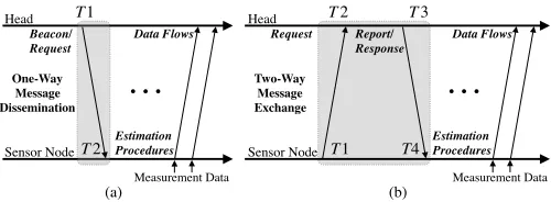
Compared to the time synchronization schemes based on the two-way message exchange, those based on the one-way message dissemination have simpler synchronization proce-dures as shown in Fig. 2 (a) (i.e., conventional one) and Fig. 1 (a) (i.e., reverse one). As a representative example of the time synchronization schemes based on the one-way message dissemination, here we discuss the details of FTSP, whose implementation is available as part of the standard TinyOS library [17], and identify issues in its implementation on resource-constrained WSN sensor nodes.
In FTSP, the linear regression is used to estimate the clock frequency ratio and offset, i.e., the slope and the intercept of the regression line. However, due to the limited computing resources of the sensor node, FTSP limits the number of timestamp samples used for the least squares estimation of the slope and intercept: Specifically, past 8 timestamp values are employed for all different synchronization intervals (SIs) during the performance evaluation in [4]. In addition to the
Head
Measurement Data
T1
T2
Report/ Response
Reverse Two-Way
Message Exchange
Sensor Node
T1
T2 T3
T4
Beacon/ Request
Report/ Response
Data Flow
Head
Two-Way Message Exchange
Sensor Node T1
T2 T3
T4
Report/ Response
Data Flow T1
T2
Reverse One-Way Message Dissemination One-Way
Message Dissemination
Measurement Data
Estimation Procedures
Estimation Procedures
Estimation Procedures
Estimation Procedures Beacon/
Request
Measurement Data
Data Flows Request
Measurement Data
Data Flows
…
…
…
…
Head
Sensor Node
Head
Sensor Node
(a) (b)
[image:3.612.313.563.54.146.2](a) (b)
Fig. 2. Overview of the conventional time synchronization based on (a) one-way message dissemination and (b) two-one-way message exchange.
SFD
preamble FLI
…
data + timestamp FCS…
timestamp T2 timestamp T1
insert
timestamp T1 sender:
receiver:
propagation delay
SFD
preamble FLI
…
data + timestamp FCS…
preamble SYNC
…
data…
CRCtimestamps sender:
receiver:
propagation delay
preamble SYNC
…
data…
CRC [image:3.612.313.562.196.274.2]byte alignment
…
Fig. 3. MAC-layer timestamping procedure introduced in FTSP [4].
linear-least-squares-based clock frequency ratio and offset esti-mation, the timestamping procedure of FTSP records multiple timestamps—i.e., timestamps at each byte boundary after the SYNC bytes as shown in Fig. 3—in sending and receiving a synchronization message to reduce the jitter of the interrupt handling and encoding/decoding times, which is also quite demanding for resource-constrained sensor nodes [4].
The authors of [6] proposed RSP, which is also based on the flooding of synchronization messages but simplifies the estimation of the clock skew and offset. In case of the head and the sensor node shown in Fig. 2 (a), their hardware clock times (i.e.,t for the head andTi(t)for the sensor node) modeled in
(3) can be described as follows:
t=αiTi(t)+βi, (3)
whereαi and βi are the clock frequency ratio and the clock
offset of the reference clock with respect to the sensor node hardware clock, respectively. Let T1k and T2k (k=1, . . .) be the timestamps corresponding to the latest Beacon/Request message received at the sensor node. Then, the logical clock
TRSP
i at the sensor node i—i.e., the estimated reference
time corresponding to the sensor node’s hardware clock—is obtained as follows [6]:
TRSP
i
Ti(t)
=αˆi,kTi(t)+βˆi,k, (4)
whereαˆi,k andβˆi,k are the clock frequency ratio and the clock offset estimated based on the linear interpolation using four timestamps, i.e.,
ˆ
αi,k =T1k−T1k−1
T2k−T2k−1
, (5)
ˆ
βi,k =T1k−1·T2k −T2k−1·T1k
C. Impact of Limited Precision Floating-Point Arithmetic on High-Precision Time Synchronization
Even with the relatively simpler clock parameter estimation procedures, RSP suffers from numerical errors caused by the limited precision of the low-cost MCUs (i.e., 32-bit single-precision floating-point numbers) of the resource-constrained sensor nodes: Specifically, the proposers of RSP suggest to use SI (i.e.,T1−T1init orT2−T2init) that is large enough to mitigate the impact of the numerical errors on the estimation of clock parameters in (5) and (6).
Likewise, the actual performance of EE-ASCFR on resource-constrained sensor nodes turns out to be poorer than expected due to the precision loss resulting from the use of single-precision floating-point numbers. In this regard, we have proposed an improved version of the scheme along with its multi-hop extension based on the reverse asymmetric framework and demonstrated satisfactory time synchronization accuracy on a real WSN testbed [11].
It is worth mentioning that the use of 32-bit single-precision floating-point format is common not only for the resource-constrained sensor node platforms (e.g., TelosB [12] and MicaZ [18]) but also for the lightweight Arduino boards [19], which are frequently used as hardware platforms for Internet of Things (IoT) prototyping as discussed in [20].
III. ENERGY-EFFICIENTTIMESYNCHRONIZATION
TAILORED FORRESOURCE-CONSTRAINEDSENSORNODES
When the propagation delay is not significant (e.g., sub-microsecond delays for WSNs with a communication range
of 300 m or less), time synchronization schemes based on
the one-way message dissemination have a clear advan-tage over those based on the two-way message exchange in terms of the number of message transmissions at sen-sor nodes. Still, the schemes based on the one-way mes-sage dissemination have issues in their implementation on resource-constrained sensor nodes as discussed in Sec. II-B. Here we introduce BATS—i.e., the energy-efficient time syn-chronization scheme based on the reverse one-way message dissemination—which addresses the implementation issues of the one-way-message-dissemination-based time synchroniza-tion schemes on resource-constrained sensor nodes.
A. Impact of Precision Loss on the Performance of One-Way-Message-Dissemination-Based Time Synchronization Schemes Taking RSP as an example, which was proposed to simplify the estimation of the clock skew and offset in FTSP, we first analyze the impact of the precision loss on the performance of the one-way-message-dissemination-based time synchroniza-tion schemes.
The impact of the precision loss on the estimated reference clock of RSP in (4) can be analyzed in a similar way to that for EE-ASCFR [11]: Letαandβ be the precision loss in the estimation of the clock frequency ratio and the clock offset, i.e.,
α ,αˆi,k−αˆi,kLP, (7)
β ,βˆi,k−βˆLPi,k, (8)
whereαˆLP
i,k and βˆi,kLPare the value of the clock frequency ratio
and the clock offset from the practical implementation that are affected by the limited-precision floating-point arithmetic in (5) and (6). The computational errorΨ(t) in the estimated reference clock at the sensor node at timet, therefore, can be derived as follows:
Ψ(t)=αˆi,kTi(t)+βˆi,k
−αˆi,kLPTi(t)+βˆLPi,k
,
=αTi(t)+β.
(9)
(9) shows that the computational error consists of two com-ponents, the first of which is proportional to the current time of the sensor node’s hardware clock (i.e.,Ti(t)).
According to the IEEE standard for floating-point arithmetic [21], a non-zero floating-point number x can be represented in the binary format as follows:
x=σ·b¯·2e, (10)
where σ is the sign taking the value of +1 or −1, b¯ is the binary fraction whose value is within the range of[1,2), and e is the integer exponent. Because the IEEE 32-bit single-precision floating-point format assigns 1 bit toσ, 8 bits to e and 23 bits to b¯, the machine epsilon[22] becomes 2−23. If the rounding arithmetic is chopping (i.e., rounding towards 0), the precision loss α is within the range of [−2−23,0], and the maximum absolute precision loss in this case is
2−23≈1.19×10⁻⁷. This implies that the first component of (9) alone could result in about0.1µsand1µscomputational errors forTi(t) of1 sand10 s, respectively, in the worst case.
Note that the analysis of the computational error above is based on the worst-case scenario for simplicity. As discussed in [6], however, in reality the precision loss α itself is inversely proportional to SI (i.e., the time difference between two consecutive beacon messages), which could more or less relax the dependency of the computational errorΨ(t)onTi(t).
In fact, setting an optimal value of SI is quite complicated because the value of SI not only affects the computational error but also determines the impact of the sensor node’s hardware clock drift due to the changes in the ambient temperature and the battery voltage.
B. Beaconless Asymmetric Energy-Efficient Time Synchroniza-tion
Now we introduce BATS and show how it can address the implementation issues on resource-constrained sensor nodes discussed in Sec. III-A and further increase energy efficiency by saving the energy for transmissions and receptions of the “Beacon/Request” messages at sensor nodes.
5
Head
Beacon Interval
T10 T20
Report/ Response Sensor Node
Reverse
One-Way Message Dissemination
Measurement Data
Estimation Procedures
T2j
Report/ Response Data Flow
Measurement Data
Estimation Procedures
T1j
Data Flows
Estimation Procedures
Timestamping Commands
T1ki−1 T1ki T1ki+1 T2ki−1
T2ki
T2ki+1 T2j−1
Report/ Response
Measurement Data
Estimation Procedures
T1j−1
…
Data…
Flow Data
Flow
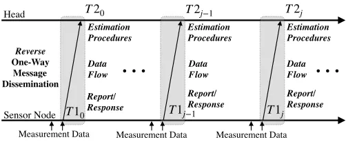
Fig. 4. Asymmetric energy-efficient time synchronization based on reverse one-way message dissemination with optional bundling of measurement data.
similar to that of the Recursive Time Synchronization Protocol (RTSP) [23]. This timestamping approach, which is based on a pair of timestamps generated during the transmission and re-ception of one message, is simpler and faster than that of FTSP [23] which reduces the jitter of interrupt handling through recording, normalizing and averaging multiple timestamps at both the sender and the receiver.
In the single-hop scenario shown in Fig. 4, the head’s direct offspring nodes employ their measurement data messages to transmit their timestampsT1j during the j-th synchronization
to the head for maintaining the time synchronization. Using the abundant computing and power resources including the 64-bit floating-point precision at the head, the numerical computational errors mentioned in Section. II could be avoided in the proposed scheme.
Instead of using the relatively simpler clock parameter estimation procedures of [10] and [6], we employ the original linear regression like [4] and [8] to model the relationship of the timestamps of the hardware clocks of the sensor node and the head, however, without the limitation on the number of past samples, e.g., FTSP uses only the past 8 samples. The following linear least squares method is employed in BATS to model the linear relationship between the hardware clocks of the sensor nodei and the head: For i∈ [0,1, . . . ,N−1]
Φi(j)=(T2i(j)TT2i(j))−1T2i(j)TT1i(j), (11)
where
Φi(j)=[1+ˆi(j),θˆi(j)],
T1i(j)=[T1i(j−m+1), ...,T1i(j)], T2i(j)=[T2i(j−m+1), ...,T2i(j)].
whereΦi(j)is the parameter set of clock skew and offset, and
j denotes the j-synchronization.
As we will see in Section V, employing the complex linear regression solution with no limitation on the sample size for solving the linear equation of the time synchronization, could improve the performance of time synchronization compared with the conventional simpler solutions described in Section II. Furthermore, applying relatively more complex solution with higher computational complexity is the natural advantage of our reverse asymmetric framework as we operate all the estimation procedures in the head with abundant computing capability instead of the resource-constrained sensor node.
As exhibited in Fig. 4, the direction of the conventional one-way message dissemination is reversed, where the estimation
SFD
preamble FLI
…
data + timestamp FCS…
timestamp T2 timestamp T1
insert
timestamp T1 sender:
receiver:
propagation delay
SFD
preamble FLI
…
data + timestamp FCS…
preamble SYNC
…
data…
CRCtimestamps sender:
receiver:
propagation delay
preamble SYNC
…
data…
CRC [image:5.612.49.300.54.157.2]byte alignment
…
Fig. 5. MAC-layer timestamping [23] adopted in BATS.
of the hardware clocks between sensor node and the head is also reversed compared to the conventional one. On the one hand, when timestamps along with measurement data from sensor nodes are gathered in the head, the corresponding hardware clock timestamps of the sensor nodes should be translated based on the head’s reference clock to estimate the exact time for the measurement events. On the other hand, optionally, when the head issues commands to notify sensor nodes to perform collaborative operations (e.g., sleep and wake-up for energy-efficient MAC protocols and application of coherent sampling), the timestamps carried in the commands have to be translated to the target sensor nodes’ hardware clock time. Using the estimated frequency ratio 1+i and
offsetθi between a sensor nodei and the head, in single-hop
scenario, the translations between their hardware clock time are represented as:
t=Ti(t) −θi
1+i
, Ti(t)=(1+i)t+θi, (12)
where the translation from sensor node’s clock time Ti(t) to
head’s clock timet involved the floating-point division, which is similar to the clock time translation in EE-ASCFR. As mentioned in [24], such calculation involved with floating-point division and microsecond-level timestamp should be carefully handled in the resource-constrained sensor nodes, but BATS is not bothered by such level of computational complexity.
IV. EXTENSION OFBATSTOMULTI-HOPWSNS
Independent of the network topologies which are typically established through routing protocols (e.g., Collection Tree Protocol (CTP) [25]), the proposed BATS scheme in principle could be extended to any existing multi-hop routing protocols with the addition of the required timestamps in the application messages. There are several issues to consider, however, in its extension to the multi-hop scenario.
In the multi-hop scenario, gateway sensor nodes located in intermediate layers process not only their own data as regular sensor nodes but also the data from their offspring sensor nodes. The presence of gateway nodes makes it complicated for the head to directly handle all timestamps required for time synchronization in multi-hop WSNs.
A. Multi-Hop Extension of The Time Synchronization Based On Reverse One-Way Message Dissemination
[image:5.612.312.564.56.147.2]Head
Sensor Nodes Time
Synchronization Maintainer
MAC-layer Time Recorder Clock Frequency Ratio & Offset Estimator
Head Clock Translator
MAC-layer Time Recorder
Report/ Response Command
Sensor Node Clock Translator
[image:6.612.51.298.56.214.2]Report/ Response Command
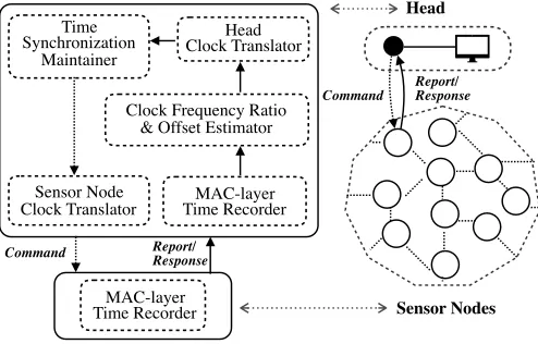
Fig. 6. A system architecture of the proposed time synchronization scheme.
on the reverse two-way message exchange (including EE-ASCFR) are those oftime-relayingandtime-translationat the gateway nodes. Of the two approaches, the time-relaying one could introduce more random delays as the messages from the sensor nodes are being transmitted to the head through multiple gateway nodes unlike the time-translation one. More-over, the random queueing delays of the synchronization messages are also not properly compensated for. To maximize the advantage of MAC-layer timestamping and avoid random queueing delays cumulated through multiple gateway nodes, therefore, we useper-hop time synchronizationfor the multi-hop extension of BATS, which is similar to the aforementioned time-translation approach in which the hardware clock time of a sensor node goes through layer-by-layer translation in order to estimate its time with respect to the reference clock of the head. The fundamental difference of the per-hop time synchronization compared to the time-translation approach, however, is that all layer-by-layer translations are again moved from the gateway nodes to the head to relieve the burden of the gateway nodes in the original time-translation approach. The system architecture is illustrated in Fig. 6, where the “command” is optional and the “sensor nodes” refer to both gateway and leaf sensor nodes.
We first extend the hardware clock time translation equation of (12) for the single-hop case to the multi-hop case where we recursively translate the hardware clock time. Consider the hardware clock time of a sensor node located at layer j of the sensor network with n layers: For j∈ [0,1, . . . ,n],
Tij(t)=Tin−k(t)=
t, k=n
Tn−k+1
i (t)−θ
n−k+1 i 1+n−k+1
i
, 0<k<n (13)
where Tij(t) is the hardware clock time of the head when k is equal to n. And the equation when 0 < k < n represents the layer-by-layer translation using the clock frequency ratio
1+in−k+1 and offset θin−k+1 of each layer.
To translate the hardware clock time of a sensor node at layer j to that based on the hardware clock time of the head (i.e.,t), we go through the following recursive procedure that
is to run at the head:
Tij(t)=
(
(1+ij)t+θij, j = 1
(1+ij)Tij−1(t)+θij, 1 < j ≤n (14)
where the clock frequency ratio1+ij and clock offset θij of each layer are all known at the head.
Note that, in the proposed per-hop time synchronization, timestamps required for the synchronization of a sensor node based on the reverse one-way message dissemination are recorded at the sensor node and its gateway node (working as a reference) as shown in Fig. 4. Unlike the time translation approach described in [10], however, the time translation operation is moved from the gateway to the head, and the gateway node just sends the pair of timestamps obtained from the reverse one-way message dissemination (i.e., T1i and T2i−1) to the head. Based on these pairs of timestamps from all the gateway nodes, the head can establish the relationships between sensor nodes and their gateway nodes and eventually translate sensor nodes hardware clock times to those based on the reference clock at the head recursively based on (13) and (14).
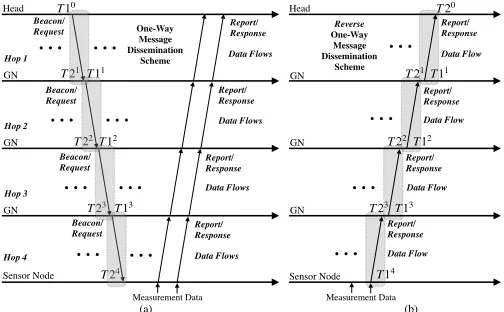
Using the aforementioned per-hop time synchronization, BATS could be extended to cover the multi-hop scenario as demonstrated in Fig. 8 (b), which is different from the conventional multi-hop scheme based on one-way message dissemination shown in Fig. 8 (a) where the synchroniza-tion timestamps are carried by standalone beacon messages and the measurement data are transported by the standalone measurement messages. The proposed BATS does not rely on broadcasting beacon messages and embeds the synchroniza-tion timestamps into the measurement messages as in [10]. In case of the conventional schemes, there are two separate flows of messages with different directions (i.e., one for syn-chronization and the other for measurement), we cannot embed synchronization timestamps into the measurement messages as in the extended BATS.
B. Comparison to Other Multi-Hop WSN Time Synchroniza-tion Schemes
Having discussed the multi-hop extension of BATS, which does not rely on beacon messages but exploits the bundling of synchronization timestamps with the measurements, we compare the extended BATS to other multi-hop WSN time synchronization schemes.
Since the synchronization timestamps are bundled with measurement data in the same message, consequently the major cost of using the proposed scheme is the payload occupation of the synchronization timestamp—i.e., T1 and T2—on the measurement message. As exhibited in Fig. 8 (b), for hop j, 2 timestamps—i.e., T1j and T2j−1—are required for the head to achieve network-wide time synchronization. Therefore, for a flat n-hop network, 2n−1 timestamps2 are transmitted through the measurement messages to the head. Note that, those timestamps (T1andT2) are also needed in the conventional scheme based on one-way message dissemination
7
(a)
Synchronization Data (T1i, T2i-1) Node Information
(Node ID (i), Parent ID (i), …)
Measurement Data #1
(!"#, $%#) …
Bundled measurement data*
Measurement Data #2 (!"&, $%&)
Measurement Data #N (!"', $%')
* If “self-data bundling” is used.
[image:7.612.131.483.55.204.2](b)
Fig. 7. Payload and data structure of a message generated at sensor nodei: (a) Payload with optional “all-data bundling” and (b) data structure with optional “self-data bundling”.
T13 Head
T11 T20
T12 T21
T22
T23
T14
Report/ Response
Report/ Response
Report/ Response
Report/ Response GN
GN
GN
Sensor Node
Data Flow
Data Flow
Data Flow
Data Flow
(b) Head
Measurement Data Report/ Response
Report/ Response
Report/ Response
Report/ Response Hop 1
GN
GN
GN
Sensor Node Hop 2
Hop 3
Hop 4
One-Way Message Dissemination
Scheme Data Flows
Data Flows
Data Flows
Data Flows
(a)
Reverse One-Way Message Dissemination
Scheme
T23 T10
T21T11
T22T12
T13
T24 Beacon/ Request
Beacon/ Request
Beacon/ Request
Beacon/ Request
… …
Measurement Data
… …
… …
… …
…
…
…
…
Fig. 8. Multi-hop extension of (a) a conventional (e.g., FTSP) and (b)
a reverse asymmetric time synchronization scheme based on the one-way message dissemination with all-data bundling procedure.
such as FTSP, however, the cost—i.e., the transmissions of the standalone synchronization messages—is much higher. Even considering that the timestampT2could be kept locally in the sensor node to perform the synchronization procedures, for a flat n-hop network, n synchronization messages which carry the timestampT1have to be broadcasted for achieving overall time synchronization. Using the self-data and all-data bundling procedure illustrated in Fig. 7, for a flat n-hop network with generatingmmeasurements each hop, the numbers of message receptions and transmissions for conventional scheme (Mconv)
and proposed scheme (Mpr op) with bundling procedures could
be quantified as follows:
Mconv=2(n−1)+1+m n Õ
i=1
2(i−1)+1 (15)
Mpr op=
n Í
i=1
(2(i−1)+1), self-data bundling
2(n−1)+1, all-data bundling
(16)
where Mconv contains not only the synchronization message
but also the measurement message. On the contrary, Mpr op
just involves the measurement message with synchronization timestamps inside. A flat 4-hop network with generating 2
measurements each hop is taken as an example with applying (15) and (16), the numbers of message transmissions and receptions for conventional scheme and proposed scheme with self-data and all-data bundling procedures are 39,16 and7. The proposed scheme with all-data bundling procedure con-serves more than 80% message transmissions and receptions compare to the conventional scheme.
Compared to the multi-hop extension of the time synchro-nization scheme based on reverse two-way message exchange proposed in [11], the multi-hop extension of BATS based on one-way message dissemination can greatly lower communi-cation overheads by reducing the number of synchronization messages required for network-wide synchronization, which is a significant advantage when used for large-scale WSNs. If the end-to-end communication range of a multi-hop WSN is over a kilometer, however, the propagation delay cannot be ignored any longer, and the time synchronization schemes based on reverse two-way messages exchange would be a better solution in such a case.
V. EXPERIMENTALRESULTS
The proposed BATS scheme is implemented on a real testbed for a flat 6-hop WSN consisting of one head and six sensor nodes, all of which are based on TelosB motes running TinyOS [17]. Note that the timer resolution of TelosB motes running TinyOS is 1µs since the resolutions of its hardware clock running on a 32-kHz crystal oscillator and software timer are30.5µsand1µs, respectively. The accuracy of time synchronization schemes tested on the testbed, therefore, is limited to a microsecond level.
A. Energy Efficiency
[image:7.612.49.301.259.415.2]TABLE I
THENUMBERS OFMESSAGETRANSMISSIONS ANDRECEPTIONS AT
SENSORNODE FORDIFFERENTSISDURINGTHEPERIOD OF3600 s
Type of Synchronization Scheme NTX1 NRX
Conventional Two-way
SI=100s 136 36
SI=10s 460 360
SI=1s 3700 3600
Conventional One-way
SI=100s 100 36
SI=10s 100 360
SI=1s 100 3600
Reverse Two-way
SI=100s 100 36
SI=10s 100 360
SI=1s 100 3600
Reverse One-way
SI=100s 100 0
SI=10s 100 0
SI=1s 100 0
1Both synchronization and measurement messages are counted.
measurements in total at the sensor node over the period of
3600 s, which are reported to the head through measurement messages without measurement bundling, and the SI is set to
1 s. The resulting number of messages—i.e., synchronization and measurement messages—transmitted (NTX) and received
(NRX) by the sensor node are summarized in Table. I.
From the comparison, we observe that the reverse one-way scheme could save the energy consumed by both transmissions and receptions of the synchronization messages; this is because the reverse one-way scheme is free from transmissions and re-ceptions of beacon messages and synchronization timestamps are embedded into measurement messages.
In the reverse two-way scheme, the “Request” synchro-nization message including timestamp T1 can be embedded into beacon messages, but still sensor nodes consume en-ergy to receive the beacon messages. On the other hand, the conventional two-way scheme requires the most message transmissions due to the sending the “Request” messages from the sensor node to the head. In addition, the conventional one-way scheme requires the same number of synchronization message receptions as in the reverse two-way scheme.
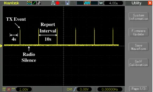
2) Direct Measurement of Energy Consumption: To mea-sure the actual power consumption of a time synchronization scheme on the resource-constrained sensor nodes, we employ a stabilized voltage supply and a digital storage oscilloscope (DSO) to power the sensor node which synchronizes with the head and log the actual power consumption as shown in Fig. 9. In the experiment setup, one 1Ωresistor is connected in series between the 3.3 V power supply and the sensor node. The two pins of the resistor are connected to the inputs of the amplifying circuit3 which used to enlarge the mA -level current input value with 150 times. The outputs of the amplifying circuit are connected to the DSO for logging the power consumption. The power consumption logged in the DSO is illustrated in Fig.10. Because the voltage is stabilized in the measurement experiment which is 3.3V constantly, so the actual power consumption could be compared through comparing the logged current value sets.
3The amplifying circuit is based on the analog devices designer guidebook
[image:8.612.55.295.89.220.2][26, chapter 4].
Fig. 9. Experiment setup for the measurement of the energy consumption on a WSN sensor node.
Fig. 10. Measuring and logging the energy consumption using DSO.
During the experiments, the measurement is generated every
2 sand the bundling procedure with bundling5measurements is employed in both FTSP and BATS for fair comparison. FTSP broadcasts and receives the synchronization beacon messages per second (i.e., default setting) and reports the bundling messages every 10 s, BATS reports the bundling messages with the measurements and synchronization data every 10 s without broadcasting or receiving—i.e., radio lis-tening deactivated—the synchronization beacons. The power and energy consumptions are computed as follows:
P(t)=V(t) ×I(t), (17)
E =
∫ te
ts
P(t)dt, (18)
where P(t),V(t) and I(t) are the instant power, voltage and current for the sensor node at timet, respectively, andEis the energy consumed by the sensor node over the time period of [ts,te]. Because the voltage V(t) is fixed to 3.3 Vduring the
experiments, we only measure the current I(t) over the two different time intervals of 60 s and600 s (i.e., te−ts in (18))
[image:8.612.313.564.248.399.2]9
0 10 20 30 40 50 60
Time [s] 0
40 70 100
Power Consumption [mW]
[image:9.612.50.300.58.177.2]FTSP FTSP-LPL BATS
Fig. 11. Power consumptions of different time synchronization schemes over
60 s.
60 600
Example Measurement Interval [s] 0
10 20 30 40 50 60 70 80
Average Power Consumption [mW]
FTSP FTSP-LPL BATS
FTSP FTSP
FTSP-LPL FTSP-LPL
BATS BATS
Fig. 12. Average power consumptions of time synchronization schemes over the measurement interval of60 sand600 s.
intervals could represent the long-term experiments. As illus-trated in Fig. 12, the average power consumption for BATS is the lowest, while the original FTSP—i.e., without using low-power mode—consumes the most power. Specifically, the FTSP employing low-power mode consumes less than one-third power of the original FTSP but more than BATS, which consumes less than5%and16%power of the original and the low-power FTSP, respectively.
B. Time Synchronization Accuracy
1) Single-Hop Scenario: We first evaluate the time synchro-nization accuracy of the proposed BATS scheme in comparison to that of FTSP with a single-hop scenario. For the experi-ments, we assume that the sensor node periodically sends mea-surement data to the head via meamea-surement messages, where 5 measurements are bundled in each measurement message for both FTSP and BATS together with synchronization data in case of the latter. We run experiments for 3600 s.
Note that BATS uses the measurement messages to carry both measurement and synchronization data, while conven-tional one-way time synchronization schemes like FTSP rely on beacon messages for synchronization data and use mea-surement messages only for meamea-surement data. For a fair comparison between BATS and FTSP, therefore, we define SI as the interval between two consecutive measurement messages carrying synchronization data for BATS and the interval between two consecutive beacon messages for FTSP, respectively, and use the same SI value for both schemes for each experiment.
Before carrying out a comparative analysis with FTSP, we need to decide the values of BATS system parameters affecting time synchronization performance. During the pre-liminary experiments, we found that the time synchronization accuracy of BATS is affected by the sample size for the linear regression for clock frequency ratio estimation. Note that, for a reasonable comparison, to find the best value of the sample sizes for different SIs, we implemented the offline re-running program in which the same raw data trace produced in the online experiment could be reused to run different offline experiments with different sample sizes. With this program, the possible sample sizes (e.g., 2, . . . , 10, . . . , 100, . . . , all) for different values of SI are evaluated. In particular, the performance of the experiment based on all samples does not outperform the one using the most recent timestamps with certain sample size value. This may result from, as time goes on, due to the aggravating clock drift, the very past sample data—i.e., very past timestamps—do not have positive contributions for the estimations of the timestamps in the most current synchronization interval. Instead, the most recent samples could provide relatively better contributions for the estimation of the most recent timestamps.
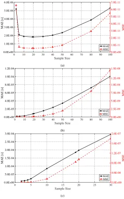
Fig. 13 shows the effect of sample size on the mean square error (MSE) and the mean absolute error (MAE) of measurement time estimation of BATS with different values of SI. From the results, we find that the MSE and MAE of measurement time estimation are minimal when the sample size is 19 and 5 for SI of 1 s and 10 s, respectively. As for the experiments with SI of 100 s, the size of total samples is quite limited (i.e., only 36 samples from the experiment over
3600 s), which means, it is quite difficult to apply large value for the aforementioned sample size. Anyhow, we still tuned the value of sample size in the range of 2–30, and the results showed that, 2 is the best sample size for the experiment with SI of100 s.
With the best empirical values of the sample sizes for various values of SI, the performance of our proposed scheme embedding the linear regression method is demonstrated. The performance of the method2of linear regression with the best parameter value outperformed the conventional methods such as the method 1 based on the calculation of the cumulative frequency ratio proposed in [6] as shown in Fig. 14. In this figure, the measurement time estimation errors of our proposed time synchronization scheme based on both traditional ratio-based method and linear regression method are demonstrated, in which the linear regression method outperforms the ratio-based method in all three report intervals at different levels. In addition, Fig. 14 demonstrated that our proposed reverse asymmetric framework could be employed on different con-ventional time synchronization schemes with diverse estima-tion methods.
Table II summarizes the MAE and MSE of measurement time estimation from the experiments during the period of
[image:9.612.50.301.220.342.2]TABLE II
MAEANDMSEOFMEASUREMENTTIMEESTIMATION OFFTSPANDBATSFOR THESINGLE-HOPSCENARIO
Synchronization Scheme MAE1[s] MSE1 NTX NRX
FTSP2
SI=100s 0.2892E-03 0.3614E-06 36 36
SI=10s 0.3164E-03 0.3983E-06 360 360
SI=1s 0.3173E-03 0.4038E-06 3600 3600
BATS with the method 1
SI=100s 2.4837E-05 2.1194E-09 36 0
SI=10s 3.2770E-06 1.7492E-11 360 0
SI=1s 2.4903E-06 1.0120E-11 3600 0
BATS with the method 2
SI=100s 8.1524E-06 1.5805E-10 36 0
SI=10s 2.1016E-06 7.3933E-12 360 0
SI=1s 1.8299E-06 5.4018E-12 3600 0
1Based on the measurement time estimation obtained from3600 ssuch that the actual performance in real deployment is represented.
2The standard FTSP implementation provided in TinyOS library offers limited millisecond-level time synchronization [27].
0 10 20 30 40 50 60 70 80 90 100
Sample Size
0.0E+00 1.0E-06 2.0E-06 3.0E-06 4.0E-06 5.0E-06 6.0E-06
MAE [s]
0.0E+00 1.0E-11 2.0E-11 3.0E-11 4.0E-11 5.0E-11 6.0E-11 7.0E-11
MSE
MAE MSE
(a)
0 10 20 30 40 50 60 70 80 90 100
Sample Size 0.0E+00
2.0E-05 4.0E-05 6.0E-05 8.0E-05 1.0E-04 1.2E-04
MAE [s]
0.0E+00 2.5E-09 5.0E-09 7.5E-09 1.0E-08 1.2E-08 1.5E-08
MSE
MAE MSE
(b)
0 5 10 15 20 25 30
Sample Size
0.0E+00 5.0E-05 1.0E-04 1.5E-04 2.0E-04 2.5E-04 3.0E-04
MAE [s]
0.0E+00 4.0E-08 8.0E-08 1.2E-07 1.6E-07 2.0E-07
MSE
MAE MSE
(c)
Fig. 13. The effect of sample size on the measurement time estimation of BATS: (a) SI=1 s; (b) SI=10 sand (c) SI=100 s.
measurement time estimation of all three different SIs show that the proposed scheme with two proposed methods provides satisfactory precision with minimum of 1.8299µs which is competitive with consideration to the results presented in other papers—e.g., conventional two-way scheme TPSN and one-way schemes FTSP and RSP—which are also evaluated
0 400 800 1200 1600 2000 2400 2800 3200 3600
Time [s] -3.0E-05
-2.0E-05 -1.0E-05 0.0E+00 1.0E-05 2.0E-05 3.0E-05
Measurement Time Estimation Error [s]
BATS(Method 1) BATS(Method 2)
(a)
0 400 800 1200 1600 2000 2400 2800 3200 3600
Time [s] -3.0E-05
-2.0E-05 -1.0E-05 0.0E+00 1.0E-05 2.0E-05 3.0E-05
Measurement Time Estimation Error [s]
BATS(Method 1) BATS(Method 2)
(b)
0 400 800 1200 1600 2000 2400 2800 3200 3600
Time [s] -3.0E-04
-2.0E-04 -1.0E-04 0.0E+00 1.0E-04 2.0E-04 3.0E-04
Measurement Time Estimation Error [s]
BATS(Method 1) BATS(Method 2)
[image:10.612.314.563.221.630.2](c)
Fig. 14. Measurement time estimation errors of BATS with ratio-based and linear regression methods with SI of (a)1 s, (b)10 s, and (c)100 s.
through real testbeds, however, with drastically fewer message transmissions as shown in Table. II.
[image:10.612.48.299.222.623.2]11
0 400 800 1200 1600 2000 2400 2800 3200 3600
Time [s] -1.2E-05
-8.0E-06 -4.0E-06 0.0E+00 4.0E-06 8.0E-06 1.2E-05
Measurement Time Estimation Error [s]
[image:11.612.49.301.56.174.2]Hop1 Hop2 Hop3 Hop4 Hop5 Hop6
Fig. 15. Measurement time estimation errors of BATS for the multi-hop
scenario.
0 1 2 3 4 5 6 7 8 9 10 11 12 13 14
0 0.1 0.2 0.3 0.4 0.5 0.6 0.7 0.8 0.9 1
Probability Hop1
Hop2 Hop3 Hop4 Hop5 Hop6
Fig. 16. Cumulative distribution functions of the absolute measurement time estimation errors of BATS for the multi-hop scenario.
TABLE III
MAEANDMSEOFMEASUREMENTTIMEESTIMATION OFBATS
FOR THEMULTI-HOPSCENARIO
Hop Number MAE1 MSE1
Hop
6 4.2580E-06 2.4586E-11
5 3.6149E-06 1.8405E-11
4 3.1341E-06 1.4519E-11
3 2.4847E-06 9.4813E-12
2 1.9455E-06 6.0164E-12
1 1.6764E-06 4.4735E-12
1Based on the measurement time estimation obtained from 3600 s
such that the actual performance in real deployment is represented.
both methods is related to the value of report intervals. This may result from the drifting of the low-cost crystal oscillator with up to tens of ppm of clock skew in the resource-constrained sensor node, in which the drifting range is typically larger in a longer interval.
2) Multi-Hop Scenario: Here we investigate the effect of the number of hops on time synchronization with a flat 6-hop WSN with one head and six sensor nodes. We set the SI to1 s
and employ the optimal sample size of 19 for the experiment. Note that we apply the self-data bundling only in order to mainly focus on the effect of the number of hops, rather than that of bundling, and thereby make the results more consistent with those of conventional schemes reported in the literature. As shown in the Fig. 15, the level of fluctuations of the measurement time estimation errors are roughly proportional to the hop counts; for instance, the measurement time estima-tion errors of the node 6 hops away from the head show the highest fluctuations, while those of the node 1 hop away from
the head show the least fluctuations. This is due to the per-hop synchronization strategy employed in BATS, where the estimation of the hardware clock time of a sensor node with respect to the reference clock relies on those of its upper-layer sensor nodes.
[image:11.612.52.300.221.342.2]Fig. 16 shows the effect of the number of hops on time synchronization in a clearer way through the cumulative distribution functions (CDFs) of absolute measurement time estimation errors. 90th-percentile absolute measurement time estimation errors for sensor nodes 1 to 6 hops away from the head are 2.8µs, 3.8µs, 4.9µs, 5.5µs, 5.9µs and 7.4µs, respectively. The MAEs and MSEs of measurement time estimation are also summarized in Table III. The results of Fig. 16 and Table III demonstrate that the proposed scheme can provide microsecond-level time synchronization accuracy for all the sensor nodes in the 6-hop WSN, even though the time synchronization error is cumulative over the hop count.
VI. CONCLUDINGREMARKS
We have proposed BATS, i.e., an energy-efficient time synchronization scheme based on the framework of reverse asymmetric time synchronization and the reverse one-way message dissemination; BATS can simultaneously address the major challenges in WSN time synchronization, i.e., lower-ing energy consumption and computational complexity while achieving high time synchronization accuracy.
The major contribution of our work in this paper is three-fold: First, the reverse asymmetric time synchronization frame-work is presented. This frameframe-work reassigns the clock param-eter estimation procedures from resource-constrained sensor nodes to the head equipped with abundant computing and power resources, which leaves only timestamping procedure at the sensor nodes. This reassignment of time synchronization can not only reduce the computational errors caused by the limited precision floating-point arithmetic at the sensor nodes but also bring further potential to use more complex estimation methods at the head, e.g., those based on machine learning techniques such neural networks as demonstrated in [28]; note that, the proposed framework could be employed by the conventional time synchronization schemes based on both one-way message dissemination and two-one-way message exchange, too.
Second, based on the reverse asymmetric time synchroniza-tion framework, BATS is proposed and extended to multi-hop WSNs, which significantly reduces the energy consumption by eliminating the need of the extra synchronization-related message—i.e., beacon message and standalone synchroniza-tion message—transmissions.
Third, the actual energy consumption and time synchro-nization accuracy of BATS are evaluated through extensive experiments on the real WSN testbed. The results demonstrate that BATS conserves up to 95% of the energy consumption by FTSP and provides1.8299µssynchronization accuracy in the single-hop scenario. In case of the multi-hop scenario, the synchronization accuracy for 1-hop and 6-hop sensor nodes are 1.6764µs and 4.2580µs respectively, which results in
As part of BATS, we have also outlined the message bundling procedure, the full investigation of which would require the consideration of its effect on the end-to-end delay of the measurement data as well as the time synchronization performance. In the follow-up work, therefore, we will carry out a systematic investigation of the effects of the bundling procedure on both synchronization and delay performance in order to identify potential issues and address them through more advanced bundling procedures.
Note that the asymmetric time synchronization framework presented in this paper fits the asymmetric Internet of Things (IoT) deployment which typically consists of a powerful server and numerous resource-constrained IoT devices [29].
ACKNOWLEDGMENT
This work was supported by Xi’an Jiaotong-Liverpool University Research Development Fund (RDF) under grant reference number RDF-16-02-39.
REFERENCES
[1] B. Sundararaman, U. Buy, and A. D. Kshemkalyani, “Clock
synchro-nization for wireless sensor networks: A survey,”Ad Hoc Networks,
vol. 3, no. 3, pp. 281–323, May 2005.
[2] I.-K. Rhee, J. Lee, J. Kim, E. Serpedin, and Y.-C. Wu, “Clock syn-chronization in wireless sensor networks: An overview,”Sensors (Basel, Switzerland), vol. 9, no. 1, pp. 56–85, Jan. 2009.
[3] Y. Wu, Q. Chaudhari, and E. Serpedin, “Clock synchronization of
wireless sensor networks,”IEEE Signal Processing Magazine, vol. 28,
no. 1, pp. 124–138, Jan. 2011.
[4] M. Maróti, B. Kusy, G. Simon, and Ákos Lédeczi, “The flooding time synchronization protocol,” inProc. 2nd Int. Conf. SenSys, Nov. 2004, pp. 39–49.
[5] B. Kusý, P. Dutta, P. Levis, M. Maróti, Ákos Lédeczi, and D. Culler, “Elapsed time on arrival; a simple and versatile primitive for canonical
time synchronisation services,” Int. J. Ad Hoc Ubiquitous Comput.,
vol. 1, no. 4, pp. 239–251, Jul. 2006.
[6] J.-P. Sheu, W.-K. Hu, and J.-C. Lin, “Ratio-based time synchronization
protocol in wireless sensor networks,” Telecommunication Systems,
vol. 39, no. 1, pp. 25–35, Sep. 2008.
[7] S. Ganeriwal, R. Kumar, and M. B. Srivastava, “Timing-sync protocol for sensor networks,” inProc. SenSys’03, Nov. 2003, pp. 138–149. [8] J. Elson, L. Girod, and D. Estrin, “Fine-grained network time
syn-chronization using reference broadcasts,” inProc. 5th Symp. Operating System Design and Implementation, Dec. 2002, pp. 147–163. [9] B. Kim, S. Hong, K. Hur, and D. Eom, “Energy-efficient and rapid time
synchronization for wireless sensor networks,” IEEE Transactions on
Consumer Electronics, vol. 56, no. 4, pp. 2258–2266, Nov. 2010. [10] K. S. Kim, S. Lee, and E. G. Lim, “Energy-efficient time
synchro-nization based on asynchronous source clock frequency recovery and
reverse two-way message exchanges in wireless sensor networks,”IEEE
Transactions on Communications, vol. 65, no. 1, pp. 347–359, Jan. 2017. [11] X. Huan and K. S. Kim, “On the Practical Implementation of Propaga-tion Delay and Clock Skew Compensated High-Precision Time Synchro-nization Schemes with Resource-Constrained Sensor Nodes in
Multi-Hop Wireless Sensor Networks,”arXiv e-prints, p. arXiv:1905.00554,
2019.
[12] “TelosB datasheet,” http://www.memsic.com/userfiles/files/Datasheets/ WSN/telosb_datasheet.pdf, accessed: 07-06-2019.
[13] F. Gong and M. L. Sichitiu, “CESP: A low-power high-accuracy time synchronization protocol,”IEEE Transactions on Vehicular Technology, vol. 65, no. 4, pp. 2387–2396, Apr. 2016.
[14] S. el Khediri, N. Nasri, M. Samet, A. Wei, and A. Kachouri, “Analysis study of time synchronization protocols in wireless sensor networks,” arXiv e-prints, pp. 1–15, Jun. 2012.
[15] J. Sallai, B. Kusý, A. Lédeczi, and P. Dutta, “On the scalability of
routing integrated time synchronization,” inProceedings of the Third
European Conference on Wireless Sensor Networks, ser. EWSN’06. Berlin, Heidelberg: Springer-Verlag, 2006, pp. 115–131.
[16] K. S. Kim, “Asynchronous source clock frequency recovery through aperiodic packet streams,”IEEE Communications Letters, vol. 17, no. 7, pp. 1455–1458, Jul. 2013.
[17] “TinyOS,” https://github.com/tinyos/tinyos-main, accessed: 07-06-2019. [18] “MicaZ datasheet,” http://www.memsic.com/userfiles/files/Datasheets/
WSN/micaz_datasheet-t.pdf, accessed: 07-06-2019.
[19] “Arduino platforms,” https://www.arduino.cc/, accessed: 07-06-2019. [20] S. K. Mani, R. Durairajan, P. Barford, and J. Sommers, “An architecture
for iot clock synchronization,” inProceedings of the 8th International Conference on the Internet of Things, Oct. 2018, pp. 17:1–17:8.
[21] IEEE Computer Society, IEEE Std 754TM-2008, IEEE Standard for
floating-point arithmetic, Std., 2008.
[22] D. Goldberg, “What every computer scientist should know about
floating-point arithmetic,” ACM Computing Surveys, no. 1, pp. 5–48,
Mar. 1991.
[23] M. Akhlaq and T. R. Sheltami, “RTSP: An accurate and energy-efficient
protocol for clock synchronization in WSNs,” IEEE Transactions on
Instrumentation and Measurement, vol. 62, no. 3, pp. 578–589, Mar. 2013.
[24] D. Djenouri and M. Bagaa, “Implementation of high precision
synchro-nization protocols in wireless sensor networks,” inProc. WOCC 2014,
May 2014, pp. 1–6.
[25] O. Gnawali, R. Fonseca, K. Jamieson, M. Kazandjieva, D. Moss, and P. Levis, “CTP: An efficient, robust, and reliable collection tree protocol for wireless sensor networks,”ACM Trans. Sen. Netw., vol. 10, no. 1, pp. 16:1–16:49, Dec. 2013.
[26] “A Designer’s Guide to Instrumentation Amplifiers, 3RD Edition,
2006,” https://www.analog.com/en/education/education-library/
dh-designers-guide-to-instrumentation-amps.html, accessed:
07-06-2019.
[27] J. M. Castillo-Secilla, J. M. Palomares, and J. Olivares,
“Temperature-compensated clock skew adjustment,” Sensors, vol. 13, no. 8, pp.
10 981–11 006, Aug. 2013.
[28] G. Cena, S. Scanzio, and A. Valenzano, “A neural network clock discipline algorithm for the rbis clock synchronization protocol,” inProc. 14th IEEE International Workshop on Factory Communication Systems, Jun. 2018, pp. 1–10.