Hard Disk Controller
Technical Manual
¢jb
ADVANCED
DIGITAL
1. INTRODUCTION ••••••••••••••
. .
.
.
. .
.
.
.
. .
.
.
. .
.
. .
.
. . .
. . .
.
. . .
.
. .
.
.
.
• Page 1 1. 1.1.2. 1. 3.
1.4.
General Description. Feat ut~es •••••••
Specifications ••••••••
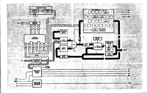
Simplified System Block Diagram.
•• Page 1 • ••• Page 2
• • Page 3
• Page 4
2. INTERFACE CONNECTORS •••••••••••••••••••••••••••••••••••••••••• Page :5
3.
4.
2. 1.
2. 2~
2.3.
Organization ••••••••••• Drive Control Signals.
2. 2. 1. RWC- •••••••••••
2. 2.2. 2. 2.3.
2. 2.4.
2. 2. 5. 2. 2.6. 2. 2. 7.
2. 2.8.
2.2.9. 2. 2. 10.
2. 2. 11.
2. 2. 12. 2. 2. 13. 2.2. 14. 2.2. 15.
Wri te Gate- •••• Seek Comp let e-. Track000- ••••• Write Fal..llt-. H80-HS2-. Sectclr-•••
Index-. Ready-. Step- ••
Direction In- •• D81-D84- ••
Control Driver/Receiver ••
50 Pin Drive Control Connector •• 34 Pin Drive Control Connector. Drive Data Signals •••••••
2.3.1. Drive Selected-.
2. 3.2.
2. 3. 3. 2. 3.4.
2.3.5. 2. 3.6. 2. 3. 7.
Timil"lg Cl'::.ck+ ••
Ti rni 1"lg Clock- ••
MFM Write Data +- •• MFM Read Data +- •••• Drive Data Connectors.
Differential Oata Driver/Receiver.
. ...
.'
.
.Page :5
• Page 5
• Page 5
••• Page 5
.Page :5
•• Page 5
• •• Page 5
• ••• Page :5
.Page 6
••• Page 6
.
.
• Page 6••• Page 6
.Page 6
• Page 6
•• Page 7
• ••• Page
e
• ••• Page 9•••• Page 9
• Page 9
•• Page 9
•• Page 9
• Page 9
• •• Page 10
• •• Page 10
• Page 10
INTERFACE TIMING ••••
.
... .
• Page 11 3. 1.3. 2.
TASK 4. 1.
4.2.
4. 3.
Drive Control Timing •••••••••
Drive Data Timing •••••
.
..
• Page 11
• • Page 12
FILE • . . • . . . . III • • • • •
.
. . .
.
.
.
.
. .
.
. . .
.
.
.
. .
. . .
.
. .
.
. .
.
. .
.
.
.
• Page 13Task Fi Ie Basics. •• Page 13
Register Array •••
.
...
• Page 13 Register" Defi rd t ions •• • •• Page 134. 3. 1. Command Register •••
. ...
• Page 134. 3.2. Status Register ••
. ...
• Page 134. 3. 3. SDH Register ••••• • Page 13
4. 3.4. CylindeY' N1..tmber •• • Page 14 4. 3. 5. Sector Number •• • •• Page 14
4. 3.6. Sect 01''' Count •• • Page 15
HOC-100l HRRD DISK CONTROLLER Technical Manual
5.
4.4. 4.5.
4.6.
4. 3. 8.
4. 3.9.
Status Status 4. s. 1.
4. 5.2.
4. 5. 3. 4. 5. 4. 4. 5.5. 4. 5.6.
4. 5. 7.
El'''l'''ol'''
4. 6. 1. 4. 6.2.
4. 6. 3. 4. 6.4. 4. 6. S. 4. 6.6. 4.6.7.
Write Precomp ••
.
.
.
. .
Data Register.Registers . . . Registers Bits ••
Errol''' •••••••• Corrected •••• Data Request •• Seek Complete •• Write Fault •• Ready.
Busy •••• Register Bits.
DAM Not Found.
TR000 Error ••••• Aborted Command ••
10 Not Fouy,d ••
CRe Error ID •••
...
Uncol'''rect ab 1 e. Bad Block. Detect ••
·
.
• •• Page·
..
·
..
• Page·
.. ·
.
~·
..
• Page·
...
• •• Page·
.
• Page· .. · ..
·
.
·
..
• •• Page· .. .
.
. · .
.
. ·
.
• •• Page· ..
·
..
• •• Page· ... · ..
•• Page.
. . .
· ..
• •• Page·
....
·
. · ...
• •• Page·
..
•• Page...
• •• Page·
..
•• Page·
.
· ..
••• Page.
.
.
.
. .
...
• Page• •• Page
·
.. ·
..
.
..
•• Page.. · ... · ..
••• Page COMMANDS ••••••••••••. . .
.
.
.
. . .
.
.
. .
. .
.
.
. .
.
. .
.
. .
. .
. .
.
. . .
• Page 5. 1.5.2.
5. 3.
5.4.
Command 5. 1. 1. 5. 1. 2.
Summary •• Stepping
DMA Read.
Rates ••
5. 1. 3.
Type I
5. 2. 1.
Loy,g Read Commands.
a.nd Write ••
·
..
5. 2. 2.
Restol'''e.
Seek .•••••
Type I I Commands.
. .
.
5.3.1. Read Sector ••
5.3.2. Multiple Sector
Type III Commands ••••
5.4.1. Write Sector ••
5.4.2. Format Track.
.
. . . .
.
.
. .
.
Rea.ds •••· ...
·
..
·
.
• Page •• Page • Page •• Page· ... .
• Page • ••••• Page ••• Page ••• Page ••• Page· ....
• Page • Page • Page Page 15 15 16 16 16 16 16 16 16 17 17 17 17 17 17 17 17 18 18 19 20 20 20 21 21 21 22 22 22 24 24 25 256. PROGRAMMING •••..••••.•..••••
.
.
. . .
.
.
.
.
. . .
.
.
. . .
.
.
. .
.
. .
.
.
. .
.
. . .
Page 276. 1.
6.2.
6.3.
6.4.
Setting 6. 1. 1.
Type I
6. 2. 1. 6. 2. 2.
6.i~.3.
6. 2. 4.
6. 2. 5.
Type I I
6. 3. 1. 6. 3. 2. 6. 3. 3. 6. 3. 4. 6. 3. 5.
Up Task Files ••••••••
Cylinders and Tracks •• Command Programming.
Steppi: ':t Rat,es ••
Use .::tf Bu:;'y Bi t.
Use of I~terrupts ••
Use of the Error Bit ••
Use of the Corrected Bit.
Command Programming. DMA Mclde ••••
Block Moves ••
.
.
.
.
DMA ••••• Usi rig
Multiple S i rn I.t 1 ate d
· . .
.
.
.
. .
.
.
.
.
Sector Tt"ansfers.Type I I I CommaY'ld
Cornp 1 et i c'ns ••
Pl''''::tgl'''amm i ng ••
· ...
6. 4. 1. FormattingM ••••••••••
6.4.2. Interleaving ••••••••••••
...
6.5. Bad Block Mapping •••••••••••••6. 5. 1. Sector Pre-allocation •••
....
6. 5.2. AlterY,ate Tracks.
....
6. 5. 3. Spare Sectors. 6. 5.4. Bad Block Bit ••
7. THEORY OF OPERATION ••••••••••••••••••••••••••••••••••
7. 1. 7.2. 7.3. 7.4. 7.5. 7.6.
General •••
.
..
Processor Functions ••
.
..
7. 2. 1. Fast 10 Select •••7.2.2. Internal Bus Control. 7.2.3. Reset Circuit •••••••• 7.2.4. Processor Power Supply. 7. 2.5.
7.2.6. 7. 2. 7. Serial 7. 3. 1. 7 .. 3 .. 2.
7. 3.3. 7. 3.4.
7. 3.5. 7. 3. 6. 7. 3. 7.
Read and Write Ports •• Read/Write Memory ••••
Miscellaneous Control Ports •• Data Separation;;;;;;; •• ==
Incoming Data Selection •••••••• Reference Clock... II II
Clock Gating •••••
High Frequency Detector •• Sample on Phase Detection •• Error Amplifier ••
veD ...
7.3.8. Window Extension ••
7.3.9. Clock Detection ••
Data Conversion and Checking ••
7. 4. 1. AM Detect ic.n ••••
7.4.2. Error Detection and Correction ••
7.4.3. Serial to Parallel Conversion. Ser"ial
7. 5. 1. 7. 5. 2. 7 n 5.3.
Data Generation •••••••••••••••• Par"a1lel
eRC/ECC
to Serial Conversion ••• Generat ion ••
Host Interface .••••• 7. 6. 1. Wa i tEnable. 7. 6. 2.
7. 6.3.
7.6.4.
7. 6.5. 7.6.6.
Bus Gating... • ••••••• Register Selection •• Interrupts and DRQs ••• Addl'''ess Select.
Boc.t Pr"c.m •••••••
...
• Page 34 • Page 35 • Page 35 • Page 36 •••• Page 36 •• Page 36
• Page 38
•• Page 38
• •• Page 38 • • Page 39 • Page 39 • Page 40 • Page 40 • •••• Page 40 • •••• Page 40 • •• Page 41 .,., Page 42 • Page 4~ • Page 43
.Page 43 • Page 43 .Page 44 • •• Page 44 • •• Page 44
• Page 4S • Page 46 • •• Page 46 • Page 46 • ••••• Page 47
• Page 48 •• Page 49 • Page 49 •••• Page 50 • •• Page 50 • •• Page 52 •• Page 52 • •• Page 53 • Page 53
• •• Page 53
Page 53
Page 54
8. MR I NTENANCE . . • • . • . . . • • . . . • • • • • • . • • • • • • • • . • . . • • • • • . • • • • • • • • • • Pa ge 55
8. 1. 8. 2.
B.3.
DRUN AdJustments .••..• Oscillator Frequency •• Balance AdJustment.
••• Page •• Page •• Page 56 56 57
A. DISK DRIVER EXAMPLE ••••••••••••••••••••••••••••••••••••••••••• Page 59
HDC-1001 HARD DISK CONTROLLER Technical Manual
A. 1. 2. A. 1. 3. A. 1. 4.
Read SectoY' •• WY'i te SectoY' ••
Task File Updating ••
• ••••••• Page 62
...
• • • • • Page 63·
...
• ••••••• Page 64B. INTERLEAVE CALCULATING UTILITV •••••••••••••••••••••••••••••••• Page 65
BII 1. BASIC Interleave Calculating Program •••••••••••••••••••• Page 66
c.
SECTOR CALCULATING UTILITV •••••••••••••••••••••••••••••••••••• Page 67C. 1. BASIC Sectors per Track Utility ••••••••••••••••••••••••• Page 68
D.
PROGRAMMERS QUICKREFERENCE ••••••••••••••••••••••••••••••••
• Page 69E.
F.
G.
O. 1. D.2. 0.3. D.4.
Task File ••••••• Va 1 i d Commands ••
SOH Register Format ••
Status and Error Register Bits.
. . . . .
... .
••• Page 69.
.
.
.
...
••• Page 69 • Page 70. ..
• Page 70OPERATING SySTEMS ••••••..•••••••••
.
. .
. . .
.
.
. . . .
. . .
. . .
.
.
. .
. .
•• Page 71 E. 1. Operating Systems Available ••••••••••••••••••••••••••••• Page 71DRAWINGS •.•..•.•
. . .
.
. . . .
.
.
. . .
.
.
.
.
.
. .
. . .
. .
.
.
.
. . .
. .
.
. .
. . .
.
•• Page 72 F. 1. Schemat i c ••.•.•.•.•••••••••••••••••••F. 1.1. Microcontroller ••••••••••••••
F. 1.2. Bus Interface/Drive Control •• F. 1. 3. Data Separator •••••••••
F. 1. 4. Serial Data Interface ••• F. 1. 5. 8100 Interface ••••••••••
APPEND I X •••••.••••••••••••••••••••••••
G. 1. G.2. G.3.
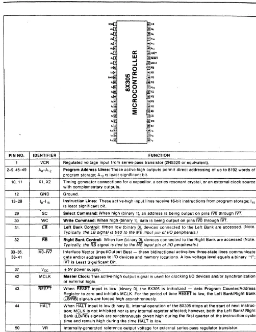
8X300 CPU ••••.•••••••••
ST506 . . . .
SA1000 or Q2000 Series ••
. .
.
·
..
. .
.
·
.. . ...
• Page 72· ...
.
....
• Page 73·
....
• Page 74·
...
.
..
••• Page 7S· ..
• Page 76. . . .
.
. . . · ...
• Page 77• Page 78
• Page 78
1. I N T ROD U C T ION
The HDC-1001 15 an 8-100 bus Winchester Controller board with error
correction (ECC) capabilities. It is designed to interface up to four Winchester disk drives. There are two versions of the board, the HDC-1001-5/B. The HDC-1001-8 can operate 811 drives. The HDC-1001-5
15 used with
ff1i:lst 5-1/411 dt"'ivesa
The drive signals are based upon the floppy look-alike interface available on the Shugart Associates' SA1000, the Seagate Technology ST506, and other =ompatible drives. All necessary buffers and receivers/drivers are included on the beard to allow direct connection to the drive. Four 20 pin radial connectors are provided for data. Either a 34 pin (5-1/411 drive) or
a 50 pin (811 dt":i.ve) cQr .... I'·lectot .. is pl'"'ovided f.:.)"'" dt"'ive centt"'c.l.
All data to be written to or read from the disk, status information, and macro cOMman~s are transferred via the 8-100 bus. An on board sector buffer allows data transfers to the host computer independent of the actual
HDC-1001 H~RD DISK CONTROLLER Technical Manual
*
8-100 IEEE 696*
Single BV Supply*
Built-ln Data Separator* Built-in Write Precompensation logic
*
Data rates up to 5 Mbits/sec* Control for up to 4 drives
*
Control for up to 8 R/W heads* 1024 cylinder addressing range
*
256 sector addressing range* CRC generation/verification
*
Automatic formatting* 128, 256, or 512 bytes per sector (User selectable>
* Unlimited sector interleave capability
* Multiple sector reads and writes
*
Overlap seek capability*
Implied seek on all commands*
Automatic retries on all errors*
Automatic restore and re-seek on seek error*
Error correction on cata field errors*
Diagnostic reads and writes for checking error correctionEncoding method: Cylinders per Head: Sectors per Track: Heads:
Drive Selects: Step rate:
Data Transfer Rate: Write Precomp Time:
eRe
Polynomial:ECC PolYYlomial:
Reciprocal ECC Polynomial: Miscorrection Probability: Non-detection Probability: Correct i orl SpaYI:
Sect Or" i rig:
HeIst Intel'''face: Drive Capability: Drive Cable Length: Power Requirements:
Ambient Operating Temperature: Relative Humidity:
MTBF: MTTR:
MFM
Up to 1024
Up to 256 (512 byte sec)
8 4
35 uS to 7.5 mS (0.5 mS increments) 4.34 Mbits/sec (SA1000)
5.000 Mbits/sec (ST506) 12 nanoseconds
X**16+X**12+X**S+1
X**32+X**28+X**26+X**19+X**17+X**10+ X**6+X**2+1
X**32+X**30+X**26+X**22+X**15+X**13+ X**6+X**4+1
256 byte sector - (8.0 E-6 512 byte sector - <1.5 E-5 -2.3 E-10
5 bits
Soft
8 Bit bi-directional Bus 10 LS Loads
10 ft. (3 M) max.
+8V, 3.0A Max (2.SA typ.)
o
C' to 50 C (32 F to 122 F) 20% to 80~~DC-1001 HARD DISK CONTROLLER Technical Manual S-100 BUS ,.!.J It 0 S T I
,
c.8.000 MHZ
rtO'l
A
...
CJIU.0
,
~ CONTMM.LATCH
•
~ o.-TA LATCH1
~ 0tI'Q. ''''"'0. Wiif.
~
'.
r CONTAOL ~'~
"OW I" I INST. IIIOM.
I
.,
IN"" .. AL IUS.
" N "'lWO,,", SlCTO" A()()IIUS
1U4I""
"fGIST!AiT
rOt-'J
I
, - - . SUttPOIn' SlGN .. 1.S
CONTMM.
,
SUttPOATr-- I.OGIC ~ COHfMM.SlGHAI.S
r----
n ... SIGN ...WOl101)07
"
I
Df'Nt CONTMM. I LATCH
...
I•
,
WO"OIJ.4' WO"0G43
--SI"'AL·
'AIUUlL ... OIT
CCNY ~
....
'''''-'4.I.IL·
----
HfIII"L lCC"C"C CONY.--
G,N <;1o&<;K("II1'II0110041 II1'II0 II Q0.01
!~IBgI2Y~!IQ~
r
-0
"
-
I v E C 0 lit T"
0 L -'N01'OQ.OI--OATA
r----S(I'AAA'OA0
"
IV
,
°
A f"
..
,
..
~ GENERATOR ~
-"NO' 100-12
-2.
I
NT E R F R C E
CON N E C TOR SThe HDC-1001 has six on board connectors. These connectors consist of a two drive control connector, and four high speed data connectors.
The drive control cable is daisy-chained to each of the four drives.
The drive data connectors carry differential signals and are radially connected. Up to four drives can be accommodated by the HDC-1001.
The Drive Control connector (J5 and J6) is a (relatively) low speed bus that is daisy chain connected to each of up to four drives in the system. To properly terminate each TTL level output signal from the HDC-1001, the last drive in the daisy chain should have a 220/330 ohm line termination resistor pack installed. All other drives should have no termination. Drive Control Signals are as follows:
2.2. 1.
RWC-2.2.2. Write
Gate-When the Reduce Write Current line is activated with Write Gate, a lower write current is used to compensate for greater bit packing density on the inner cylinders. The RWC- line is activated when the cylinder number is greater than or equal to four times the contents of the Write Precomp Register.
This output signal allows data to be ~ritten to the
disk~
2.2.3. Seek
Complete-2.2.4. Track 000-2.2.5. Wri te F.aul t -2.2.6.
HS0-HS2-Infot"'ms the drive has
s tab iii zed.
HDC-1001 that the head of the selected reached the desired cylinder and has Seek Complete is not checked after a SEEK command, thus allowing overlapped seeks.
Indicates that the R/W heads are positioned on the outermost cylinder. This line is sampled immediately
before each step is issued.
HDC-1001 HARD DISK CONTROLLER Technical Manual
2. 2. 7.
2. 2.8.
2.2.9.
2.2. 10.
2. 2. 11.
2.2. 12.
Sector-
Inde>e- Ready-
Step-For hard sectored drives, this line is used to indicate the sector boundries during formatting. Note that this line is not used unless special PROMs are installed to handle hard sectored drives.
Is used to indicate the index point for synchronization during formatting and as a time out mechanism for retries. This signal should pulse once each rotation
elf the disk.
Informs the HDC-1001 that the desired drive is selected and that its motor is up to speed. The HDC-1001 will not execute commands unless this line is true.
This line is pulsed once for each cylinder to be stepped. The direction of the step will be determined
by t~E:' Directiorl In- lirle. The step p,-,lse peric,d is
determined by the internal stepping rate register during implied seek operations or explicitly during Seek and Restore commands. During auto restore, the
ste~ pulse period is determined by the Seek
Complete-time from the drive. Direction
In-
081-084-Determines the direction of motion of the R/W head when the step line is pulsed. A high on this line defines the dlrection as out and a low defines direction as in. These four Drive Select lines are used to select one of four possible drives.
2.2.13. Control Driver/Receiver
The control lines have the following electrical specifications: True= 0.0 V to 0.4 V at lin
=
40 rna.False= 2.5 V to 5.25 V at lin = -0 ma.
HDC-1001 HARD DISK CONTROLLER Technical Manual
2.2.14. 50 Pin Drive Control Connector
This Drive Control Connector (J5) is a 50 pin vertical header on tenth-inch centers that mates with Burndy #FRS50BS. The cable used should be flat ribbon cable or twisted pair with a length of less than 10 feet. The cable
pin-outs are as follows:
+---+
Signal Ground
13 15 17 19 21 23 25 27 29 31 33 35 37 39 41 43 45 47 49
Sig1",al Pin
4 6 8 10 12 14 16 18 20 22 24 26 28 30 32 34 36 38 40 42 44 46 48 50 I/O
a
Ia
Ia
I I 0a
a
a
0a
0 I ISignal Name
Head Select
0Sectot ..
-Head Select
1- Index- Ready-NC
Drive Select
1-Drive Select
2-Drive Select
3-Drive Select
4-Direction
In- Step-NC
Write Gate-
TR000-Write Fault-NC
NC NC
+---+---+---+---+
2.2.15. 34 Pin Drive Control Connector
This Drive Control connector (J6) is a 34 pin vertical header on tenth-inch centers that mates with Burndy #FRS34BS. The cable used should be flat ribbon cable or twisted pair with a length of less than 10 feet. The cable pin-outs are as follows:
+---+
I Signal Ground Signal Pin 1\0 Signal Name . +---~---+---+---+---+
1 2 0
RWC-3 4 0 Head Select
2-5 6 0 Wt"i te
Gate-7 8 I Seek
COl'l1plete-9 10 I
TR01Z10-11 12 I W""'ite
Fault-13 14 0 Head Select
0-15 16 I
Sectc.t"-17 18 0 Head Select
1-19 2121 I
Index-21 22 I
Ready-23 24 0
Step-25 26 0 Dl'''ive Select
1-27 28
a
Drive Select2-29 3121 0 Dt"ive Select
3-31 32
a
Drive Select4-33 34 0 Dit"ect ion
In-+---+---+---+---+
The Drive Data Connectors carry the high speed differential MFM data between the drive and the HDC-1001. Due to the loading characteristics of these differential lines, each of the drives have their own data connector. Drive Data Signals are as follows:
2.3.1. Drive Selected-2. 3.Selected-2.
This Signal is not used on the HDC-1001. Timing Clock+
One half of the differential TiMing Clock signal. line contains a square wave signal equal to 1/64 frequency of the write clock crystal.
2~3.3. Timing
Clock-This is the complimentary version of Timing Clock+. 2.3.4. MFM Write
Data+-This the
HDC-1001 HARD DISK CONTROLLER T.chnical Manual
2.3.5. MFM Read
Data+-Differential MFM data from the disk to the controller. 2.3.6. Drive Data Connectors
Four Data connectors (J1-4) are provided for clock signals and data between the HDC-1001 and each drive. All lines associated with the transfer of data between the drive and the HDC-1001 system are differential in nature and may not be multiplexed. The Data connectors are 20 pin vertical headers on tenth-inch centers that mate with Burndy #FRS20BS. The cable used should be flat ribbon cable or twisted pair with a length of less than
10 feet. The cable pin-outs are as follows:
+---+---+---+---+ Signal Ground Signal Pin I I/O Signal Name
+---+---+---+---+
t 2 1 I Drive Selected
I 4 3 NC
6
8
11
12
15
16
19
20
5
7
9
10
13
14
17
18
I
0 0
0
a
I I
Write Pl'''otect-NC
Timing Clock+ Timing Clock-GND
GND
MFM Wl'"'ite Data+
MFM Wl'''ite Data-GND
GND
MFM Read Data+
MFM Read Data-GND
GND
+---+---+---+---+ 2.3.7. Differential Data Driver/Receiver
HIGH _ ...
TRUE
AMO 26LS31
or
75110ANOTE: ANY AS 422 DRIVER/RECEIVER PAIR WILL INTERFACE
51Q
51Q
--FLAT RIBBON OR· TWISTED PAIR
MAX 10 FT.
10
~_HIGH
TRUE
3.
I N T E R F ACE
T I III I N B+---+
i SYMBOL CHARACTERISTIC MIN· MAX UNITS
+---~---+
I tWa Write gate pulse width 1 sector 2 rotation I
I tDS Direction to step delay 250 "S I tSW Step pulse width S(typical) uS
I tSP Programmed Step pulse period 0.01 7.5 uS
I tSS Step to Seek Complete false 9 uS
I tSC Last Step to seek Complete 128 Index
I times
+---+
Notes:
1. Write gate pdlse width will V';;'··y depending e.n the sector size and
the rotation rate of the dis~.
2. Step pulse period wi 11 be er.p~al to seek complete time dl.tt"'ing auto
t"es t l:tre .
-ORSE~HDSEL:JC
______
-.~---·--~~~---:---x:::
- RWe
%07i1iZliil
VAUD<,~
__J21.L7!I/!ZITJZ///JIIZ7liZZZ!l
-WRITE GATE
I I
1 -tWa ---···'··~I
I •
I
---~~~~---i
tDS-;
i I j
-- DIRECTION
Z{7ij?~:>:T/lJZJ
~ _ _ m, . - - - -....
J
J~--; 1 . . - - - tSP _,
I
-:tSW:-
I-STEP---~---~L 1~---~
___
~r_4J
II : I
tSS-t , - I· tSC
----I ,..'
---4}
J
IDC-1001 HARD DISK CONTROLLER Technical Manual 1~!EBE8~E !l~l~§
+---+
I SYMBOL CHARACTERISTIC MIN MAX UNITS
+---+
tTC Timing clock period WCLK/16 (typical) tWD Write data pulse width 60 120 nS
tRD Read data pulse width 25 nS
+---+
+
TlMING ClOC' i
-- TlMING CLOCK
-...-I . i
: .... tTC-.4
,
+
MFM WRITE DATJU
I
, ~ tWO
- MFM WRITE DATl
n ... : _
.. :
+
MFM READ DATJU
I I
~ tRO
I
I - MFM READ DATA
i
l
n~
12
~
4. T ASK
F I L E
The HDC-1001 performs all disk functions through a set of registers called the Task File. These register are loaded with parameters such as Sector Number, Cylinder Number, etc., prior to issuing a command. Individual registers are selected via A0-2. The following registers are available:
+---+
I CS- I A2 I Al I A0 I RE-
WE-+---+
1 X X X I Deselected Deselected I
0 0 0 0 I Data Register" Oata Register I 0 0 0 1 Ert"clt" Reg istet" Wt"i te Precomp t
0 0 1 0 Sectot" COUYlt Sect en'" Count
0 0 1 1 SectlJt" Number Sectot" Number
0 1 0 0 Cylinder Lelw Cylinder Low
0 1 0 1 Cyl indet" High CyliYldel''' High
0 1 1 0 Size/Or"ive/Head Size/Or" i ve/Head
0 1 1 1 Status Register CI::wrllmaYld Register
+---+
4.3.1. Command Register
All commands are loaded into this register after the task registers have been set. Writing to this register will cause the INTRQ Line to be reset. The Command register is a write-only register.
4.3.2. Status Register
4.3.3. SDH Register
After execution of a command, the Status register is internally loaded with status information pertaining to the command executed. The host Must read this register to determine successful execution of the command. The Status register is a read-only register; it cannot be written to by the host. If the busy bit is set, no other bits in this register are valid. Accessing this register will cause the INTRQ line to be reset.
HOC-1001 HARD DISK CONTROLLER Technical Manual I8§~ E!b~ read/write register organized as follows:
+---+
I 7 1 6 5 1 4 3 I 2 1 0
+---+
I E I Sec J Drive I Head Size I Select I Select
+---+
E=O eRC in data field
E=l ECC in data field
+---+
+---+
Bit Bit Sector Size Bit Bit Drive Selected
6 5 4 3
+---+
+---+
o
0 256 Byteso
0 Drive Sel 1o
1 512 Byteso
1 Drive Sel 21 1 128 Bytes 1 0 Drive Sel 3
+---+
1 1 Drive Sel 4+---+
+---+
Bit Bit Bit Head Selected
2 1 0
+---+
0 0 0 Head 0
0 0 1 Head 1
0 1 0 Head 2
0 1 1 Head 3
1 0 0 Head 4
1 0 1 Head 5
1 1 0 Head 6
1 1 1 Head 7
+---+
4.3.4. Cylinder Number
4.3.5.
These two read/write registers form the cylinder number where the head is to be positioned on a Seek, Read, Write, or Format command. Internally, a separate set of cylinder register values are maintained for each drive. The two least significant bits of the Cylinder
High register form the most significant bits of the cylinder number as illustrated below:
Register bits: Cylinder bits: Sector number
This prior
~~!lnQ~~ ~lgb
17161514131211101
I I I I I I 19181
~~!inQ~~ bQ~
17161514131211101 17161514131211101 register is loaded with the desired sector number
to a Read or Write command. The Sector Number
4.3.6.
4.3.7.
4.3.8.
4.3.9.
Sector Count
register is a read/write register and may be read or written to by the host.
This read/write register is loaded with the number of sectors to be processed. On Read or Write multiple commands, the number of sectors to be transferred is loaded into this register. During a Format command, this register is loaded with the number of sectors to be formatted. During the course of a command, the Sector Count register is decremented towards zero and should be re-loaded for each COMmand.
Error Register
This register contains specific fault information per-taining to the last command executed. This register is valid only if the Error bit in the Status register is set. The Error register is read only.
Write Precomp
The Write Precompensation register holds the cylinder number where the RWC line will be asserted and Write Precompensation logic is to be turned on. This write-only register is loaded with the cylinder number divided-by-4 to achieve a range of 1024 cylinders. For example, if write precompensation is desired for cylinder 128 (80 Hex) and higher, this register must be loaded with 32 (20 Hex). The Write Precompensation delay is fixed at 12 nanoseconds from nominal. On drives that require separate write precompensation and reduce write current cylinders, set the Write Precomp register to the cylinder where write current reduction
is desired. Data Register
HDC-1001 HRRD DISK CONTROLLER Technical Manual
18it:S E!bs
There are two registers in the HDC-1001 that are used to monitor the execution of commands. They are the Status register and the Error register. Each bit of these registers is used to define a particu)ar type of status or error COYld it ion.
+---+
Bit Status Register Error Register
+---+---+---+
I 7 Busy Bad Block Detect
I 6 Ready Uncorrectable
I 5 Write Fault CRC Error - 1D Field
J 4 Seek Complete ID Not Found
I 3 Data Request
2 Corrected Aborted Command
TR000 Error
1
o
El'''ror DAM Not Found+---+
4. 5. 1. Error
4.5.2. Corrected
4. S. 3. Data Request
When set, indicates that a bit is set in the Error register. It provides an efficient means of checking for an error condition by the host. This bit is reset on receipt of a new command.
Indicates that there was a read error condition either in the data field or the ECC check bits themselves, and that the controller was able to correct the condition. Functions almost identically to the hardware DRQ line. When set, it indicates that the sector buffer is ready to accept data or contains data to be read out by the host. The Data Request bit is reset when the sector buffer has been fully read from or written to. Normally, the host need not consult this bit to determine if a byte should be transferred.
4.5.4. Seek Complete
4.5.5.
Wl"'ite Fault
Indicates the condition of the Seek Complete line on the selected drive.
Indicates the condition of the Write Fault line on a
4.5.6. Ready
4.5.7.
Busyselected dt"ive. The HDC-1001 will not execute any command if this bit is set.
Indicates· selected
the condition of the Ready drive. The HOC-1001 will not commands unless this bit is set.
1 iYle of execute
the
aYry
Aftet" issuing a commar,d, this bit will be set, indicating that the HDC-1001 is busy executing a command. No other bits or registers are valid when this bit is set.
4.6.1. DAM Not Found
4.6.2. TR000 Error
Will be set during a Read Sector command if, after successfully identifying the IO field, the Data Address
mark was not detected within 16 bytes of ID field. Will be set during a Restore command if,
1024 stepping pulses, the Track 000 asserted by the drive.
aftel'''' issuiy,g
1 i rle was not 4.6.3. Aborted Command
4.6.4.
ID
Not FOUYld4.6.5.
CRC ErrorID
Indicates that a valid command has been received that cannot be executed, based on status information from the drive. For example, if a write sector command has been issued while the Write Fault line is set, the Aborted Command bit will be set. Interrogation of the
Status and/or Error registers by the host can be
performed to determine the cause of failure.
When set, this bit indicates that an 10 field containing a specified cylinder, head, sector number or sector size was not found.
Indicates that a CRe error was encountered in an
ID
HDC-1001 H~RD DISK CONTROLLER Technical Manual Ie§~ Elb~
4.6.6.
4.6.7.
Uncorrectabla
Indicates that an error was detected while reading the data field or ECC check bits and the error was so severe that the controller was not able to correct the condition.
Bad Block Detect
Indicates that a Bad Block Mark has been detected in the specified ID field. If the command issued was a write sector command, no writing will be performed. If generated from a read sector command, the data field will not be read. Note that bad block will not be detected if the flaw is in the 10 field unless multiple
10 fields were written.
5.
COM MAN D S
The HDC-1001 executes five easy to use macro commands. Most commands feature automatic 'implied' seek, which means the host system need not tell the HDC-1001 where the R/W heads of each drive are or when to move them. The controller automatically performs all needed retries on all errors encountered including data field errors. If the data field contains an error, the controller will perform a correction, if possible. If the R/W head misposit ions, the HDC-1001 wi 11 automat ically perform a l'''estore and a re-seek. If the error is completely unrecoverable, the HDC-1001 will simulate a normal completion to simplify the host system's software.
HDC-1001 HRRD DISK CONTROLLER Technical Manual
§~!~ ~2mm~Dg §Ymm~~~
For ease of discussion, commands are divided into three types which are summarized in the following table:
+---~---+
BITS I
TYPE COMMAND 7 6 5 4 3 2 1 0 I
+---+---+---+
I Restore 0 0 0 1 r3 r2 rl r01
1---+---+---+
I I I Seek I 0 1 1 1 r3 r2 rl r01
1---+---+---+
I II I Read Sector I 0 0 1 0 D M L 0 I
1---+---+---+
I III 1 Write Sector I 0 0 1 1 0 M L 0 I
1---+---+---+
1 III I Format Track I 0 1 0 1 0 0 0 0 I
+---+
L=Long Read/Write M=Multiple Sector
D=OMA Read Interrupt rX=Stepping Rate
~.1.1. Stepping Rates
+---+
r3-r0 - Stepping Rate
1---+---+
I 0000
=
35 uS I 1000=
4.0 mS II 0001 = 0.5 mS I 1001 = 4.5 mS I
I 0010
=
1.0 mS 1010=
5.0 mS I 0011=
1.5 mS 1011=
5.5 mSI 0100 = 2.0 mS 1100
=
6.0 mS 0101=
2.5 mS0110
=
3.0 mS 0111=
3.5 mS1101
=
6.5 mS1110
=
7.0 mS 1111=
7.5 mS+---+---+
5.1.2. DMA
Read
Q
=
Q~e B~~g ~QQ~o
= Programmed I/O Mode1 = DMA Mode
The OMA bit is used to position
INTRQ
in relation to DRQs during the read sector command. If the DMA bit is reset (0=0), the interrupt will occur before the first DRQ. This allows the programmed I/O host to intervene and transfer the data from the sector buffer. If the DMA bit is set (0=1), then the interrupt will occur only after the system DMA controller has transferred the entire buffer of data.5.1.3. Long Read and Write
If the Long bit is set, a special diagnostic read or write will be performed. During normal reads or writes, the ECC check bytes are not visible to the user. The Long bit allows the user to read and write these normally invisible bytes.
During a Read Long, the HDC-1001 will return a sector that is four bytes longer than the selected sector size. These four bytes will be the ECC check bits as recorded on the disk. During a Write Long, the host give the HDC-1001 a sector that is four bytes longer than normal. These four extra bytes are recorded in place of the ECC bytes that are normally written after each sector.
The Read and Write Long option may only be used when the HDC-1001 is in ECC mode.
These commands simply position the R/W heads of the selected drive. Both commands have explicit stepping rate fields. The lower four bits of these commands form the stepping rate which is stored for later Read, Write or format operations.
5.2.1. Restore
The Restore command is used to calibrate the position of the R/W head on each drive by stepping the head outward until the TR000 line goes true. Upon receipt of the Restore command, the Busy bit in the Status Register is set. Cylinder High and Cylinder Low registers are cleared. The lower four bits of the command byte are stored in the stepping rate register for subsequent implied seeks. The state of Seek Complete, Ready and Write Fault are sampled, and if an error condition exists, the Aborted command bit in the Error register is set, the Error bit in the Status register is set, an interrupt is generated, and the Busy bit is reset.
HDC-1001 HARD DISK CONTROLLER T.~hnical Manual
5.2.2. Seek
The Seek command positions the R/W head to a certain cylinder. It is primarily used to start ~wo or more concurrent seeks on drives that support buffered stepping. Upon r~ceipt of the Seek command, the Busy bit in the Status Register is set. Th~ lower four bits of the command byte are stored in the stepping rate register for subsequent implied seeks. The state of Seek complete, Ready and Write Fault are sampled, and if an error condition exists, the Aborted command bit in the Error register is set, the Error bit in the Status register is set7 an interrupt is generated, and the Busy bit is reset.
If no errors are encountered thus far, the internal head position register for the selected drive is updated, the direction line is set to the proper direction and a step pulse is issued for each cylinder to be stepped. When all stepping pulses have been issued, the Busy bit is reset and an interrupt is issueda Note that the Seek Complete line is not sampled after the Seek command, allowing multiple seek operations to be started using drives with buffered seek capability.
This type of command is characterized by a transfer of a block of data from the HDC-1001 buffer to the host. This command has an implicit stepping rate as set by the last Restore or Seek command.
5.3.1. Read Sector
The Read Sector command is used to read a sector of data from the disk to the host computer. Upon receipt of the Read command, the Busy bit in the Status register is set. The state of Seek Complete, Ready and Write Fault are sampled, and i f an error condition exists, the Aborted Command bit in the Error register is set7 the Error bit in the Status register is set, and a normal completion is simulated.
Implied Seek
If no errors are encountered so far, a Seek command is executed. The Seek Complete line is sampled. If the Seek Complete line does not go true within 128 Index pulses? then the Aborted command bit in the Error register is set, the Error bit in the Status register is set, and a normal completion is simulated.
Retries
Once the head has settled over the desired cylinder, the HDC-1001 will attempt to read the sector. The HDC-1001 performs all retries necessary to recover the data during the read command. The controller attempts to read the desired sector up to 16 times. It will attempt a retry if it does
not find an 10, if the ID of that sector has a bad CRC, if the Data Address Mark (DAM) couldn't be found, or even if the data was actually read from the disk but was in error.
Error Correction
If an error was detected while reading the data field, the controller will attempt to correct the error, If the error was correctable, the Corrected bit in the status register will be set and the command resumed. If it was uncorrectable, the Uncorrectable Error bit will be set, the Error bit in the Status register is set, and a normal completion is simulated.
Aut.:;) Restor"e
Every time the controller encounters an error, it records the occurrence of that error in an internal register. If, after 16 retries, the controller was not able to get a match on the ID field, it assumes that the head was possibly mis-positioned and executes an auto-restore. During the auto-restore, the stepping rate is implied to be equal to the Seek Complete pert.::wd. If the TRK000 dl:Jes YI.::wt go true withiYI 1024 steps, the TRK000 Error bit in the Error register is set, the Error bit in the Status register is set and a normal completion is simulated.
After the auto-restore has been successfully completed, the controller re-seeks and attempts to read the sector once again. An auto-restore will be
performed only once per read or write sector command.
HDC-1001 HARD DISK CONTROLLER Teehnical Manual
Error Severity Levels
Although the HOC-1001 might encounter any number of errors in the course of
executing a command, it only reports the most severe error. Errors are
ranked from most severe to least severe as follows.
1. Aborted Command 2. TR000 E,,"ror
3. Bad Block*
4. Urlcorrect a b I e
5. Data Address Mark Not Found
6. 10 CRC Error
7. ID Not Found
* -
Bad Block will only be detected if there is no 10 eRC Error or 10 NotFound Error in the sector with the Bad Block bit set.
Normal Completion
If the HDC-1001 encountered no errors, it is considered a normal
completion. The busy bit is reset. The status of the DMA bit in the
command byte is examined. If this bit is reset (0=0; programmed 1/0 mode)
then an interrupt is issued at this time. DRQs are then generated for each
byte to be ,,"ead from the buffer. (Note: It is recommeYlded that programmed
I/O transfers should take place as a block move without consulting the ORQ
bit in the Status Register.) After all the data has been moved from the
buffer, the DMA bit in the command byte is consulted again. If this bit is
set (D=l; OMA mode) then an interrupt will be issued.
5.3.2. Multiple Sector Reads
If the M bit in the command byte is set, then the HDC-1001 will attempt to
read multiple sectors. After all the data has been transferred from the
sector buffer to the host on a read, the Sector Number register is
incremented, the Sector Count register is decremented, and if the Sector
Count reaches zero or if a fatal error is encountered, the HDC-1001 will
stop and interrupt the host.
When a Correctable error is encountered during a multiple sector read, the
occurance of the error is logged, but no interrupts are generated. After
the whole multiple transfer is complete, the host can read the Corrected
bit of the Status register to determine if any automatic corrections have
taker. place.
This type of command is characterized by a transfer of a block of data from
the host to the HDC-1001 buffer. These commands have implicit stepping
rates as set by the last Restore or Seek command.
5.4.1. Write Sector
The Write Sector command is used to write a sector of data computer to the disk. Upon receipt of the Write command,
generates DRQs for each byte to be written to the buffer. recommended that programmed I/O transfers should take place without consulting the ORQ bit in the Status register.)
from the host the controller (Ne.te: It is as a block move After all data has been sent to the sector buffer, the Busy bit in the Status register is set. The state of Seek Complete, Ready and Write Fault are sampled, and if an error condition exists, the Aborted Command bit in the Error register is set, the Error bit in the status register is set, an interrupt is generated and the Busy bit is reset.
Retries
Once the head has settled over the desired cylinder, it will attempt to read the 10 of the sector. The HOC-1001 performs all retries necessary to recover the Id during the write command. The controller attempts to read the 10 of the desired sector up to 16 times. It will attempt a retry if it doesn't find an 10 or if the ID of that sector has a bad CRe.
Auto Restore
Every time the controller encounters an error, it records the occurrence of that error in an internal register. If, after 16 retries, the controller was not able to get a match on the ID field, it assumes that the head was possibly mis-positioned and executes an auto-restore. During the auto-restore, the stepping rate is implied to be equal to the Seek Complete period. After the auto-restore has been successfully completed, the controller re-seeks and attempts to write the sector once again.
Hard Errors
If the controller encounters a non-recoverable error, the controller examines its internal error history register. It then sets the bit in the Error register of the highest severity error incurred. The Error bit in the Status register is set, an interrupt is generated and the Busy bit is reset.
If the proper sector is located, the sector buffer is written to the disk, an interrupt is generated and the Busy bit is reset.
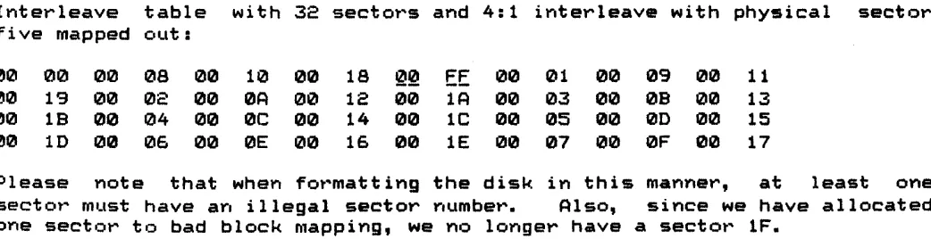
5.4.2. Format Track
HDC-100t HARD DISK CONTROLLER Technical Manual
part icular disk. Upon if . . . ~'Ci3.p~ of the Format command, the controller
generates DRQs for C?d'lch b:)/' .J OY ~he interleave table to be written to the
buffer. Information O~ . J~~in~ up an interleave table can be found in
Sect ion 7. In &11 C~Qc),'v \;:-u~ number of bytes transferred to the buffer must correspond
to
th@ ell.:.i'""v·=:w;l'~ gl!?ctor size.After all data has b@0tl L;.:~ '~o ~h~ buffer, the Busy bit in the Status
reg i.ter is set. Th~ S\;.~.:\"; of SG?~k Complete, Ready and Wri te Faul t 1 ina.
are sampled. If an ~r"r'O~:~ i:;'~)Ir"ydition exists, the Aborted Command bit in the Errol''' register is S(€)\';<J '\;t>'k.;\ ~rror bit in the Status register is set, an
interrupt is generateti ali'J: )'0·Q BlLtfSy bit is reset.
Implied Seek
If no erro,,"s are G:?V"lC04.,.i'I\;!~i'i:'~dl ~o far, a Seek comma rid is executed. No verification of track PC~l~~o~ine aeeuracy is performed because the track may not have any ID fiQl~l; ~rQS~ntD After the Seek operation has been performed, the Seek COMplG~~ lin~ i~ sampled. If the Seek Complete line is riot asserted withit'l J.:1 :,V'bdJ~K pul§es, the Aborted Command bit in the Error register is S~~V ~~ror bit in the Status register is set, an
interrupt is genera.ted loU'Hj \;rl~ Busy bit is reset.
Once the head has settled cv~r th@ d~sired cylinder, the controller waits until the Index line is a5m~~ted. Once the index is found, a number of ID fields and nulled d~~~ li~lds are written to the disk. The number of sectors written is equQl to th~ cont~nts of the Sector Count Register. As each sector is wrl~~@n ~nQ S~ctor Count Register is decremented, and consequently, must be updated before each format operation.
After the last sector is written, the controller back-fills the track with 4E's. When the next ind~x pulse after the last sector is written is encountered, the format operation is terminated, an Interrupt is generated and the Busy bit is reset.
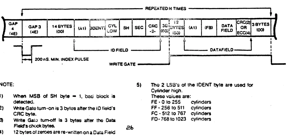
Tr"ack Format
The Format command formats the track usin~ the following format:
•
REPEATEONTIMes
---.,l •
148YTES
(oot
/
r"',=="""I',F"\ If'"=y .... II~--;--~C ... £lC'1lG;fA-'!Inm;:= .. -~ ~ - OATA CRC(2) 3 BYTeS
f
(AU lID~N1~"""" ~ SH SEC " ... ~I::JVYES (AU (FB) ORI
j bOW -2· (ntH: (00, FIELD ECC(4) (00.
•
:
~I
I
-, r
'-. ---
10 FIELDL
DATAF'ELO.--Jq
200 nS. MIN. I.NOEX PUl.SeWRITE GATE - - - -..
NOTE:
1) When MSB of SH byte - 1, bad block is
detected.
2) Write Gate tum-on is 3 bytG'S after the iO fiekJ's
CRe byte.
3) Write Gaia tum<lff Is 3 bytes after
too oata
Fiekts ch<x:k bytes.4) , 2 bVtH of zeroes are ra-written on a Oat;; Field
5) ThQ 2 LSS'g of the IDENT byte are used for
Cylinder high.
Thesa VCliues are:
FE -Q to 255 cylinders
FF - 256 to 511 cyiinders
Fe ~ 512 to 767 cylinders
FO- 768 to 1023 cylinders
I •
I I
•
[image:32.612.42.534.535.767.2]6. PRO G RAM MIN
e
Users familiar with floppy disk systems will find programming the HDC-1001 a pleasant surprise. A sUbstantial amount of intelligence that was required by the host computer has been incorporated into the HDC-1001. The HDC-1001 performs all needed retries, even on head positioning errors. If there is an error in the data field, the HDC-1001 will attempt to correct it. Most commands feature automatic 'implied' seek which means that seek commands YJeed rlc.t be issued to perfo1'''m basic read/write functions. The HDC-1001 keeps track of the position of up to four read/write head assemblies, so the host system does not have to maintain track tables. All transfers to and from the disk are through an on-board full sector buffer. This mearls that data t ... "ansfe1'''s iu"e fully interruptable arid can take place at any speed that is convenient to the system designer. In the event of an unrecc.verable e1'''1''''01'''' , the HDC-1001 simulates a n01'''mal complet ion so that special e1'''ror recovet"'y software is not needed.
Before any of the five commands may be executed, a set of parameter registers called the Task File must be set up. For most commands, this informs the HDC-1001 of the exact location on the disk that the transfer should take place. For a normal read or write sector operation, the Sector Number, the Size/Drive/Head, Cylinder Number and Command register (usually in that order) will be written.
Note that most of these registers are readable as well as writable. These registers normally are not read from, but this feature is provided so that error reporting routines can determine phYSically where an error occurred without recalculating the sector, head and cylinder parameters.
Since the HDC-1001 can recall all the Task File parameters sent to it, it is recommended that Task File parameters be stored in the HDC-1001 as they are calculated. This will save the programmer a few instructions and microseconds by not maintaining two copies of the same information.
6.1.1. Cylinders and Tracks
Since most har"'d disk dt"'ives contain more than or,e head per positioner, it is more efficient to step the R/W head assemblies of most disk drives by cylinders, not tracks. In other words, the disk driver software should be deSigned to read or write all data that is directly accessible by all the heads on a positioner before stepping to a new cylinder. The following example illustrates a cylinder-by-cylinder sequential file read on a four head, two platter disk drive:
+---~---+
Physical Logical Physical Physical Cylinder Head Number Head Side I Platter
+---+---+---+---+
I 25 I 3 Top BI 26 I 0 Bottom A
I 26 I 1 Top A
26 2 Bottom B
26 3 Top B
27 0 Bottom A
+---+
Restore and Seek are Type I commands. These commands position the R/W heads of the selected drive and set the implied stepping rate register. No data is tt"'ansferred to or from the Data Register. To executa a Type I command, the system software must do the following functions in this order:
1. Set up Task File and issue command with stepping rate
(HDC-1001 will attempt to execute Type I command)
2. Wait ~or interrupt or for Busy bit in Status Register to be reset 3. Check Error bit in Status Register for proper completion.
6.2.1. Stepping Rates
Most drives that use the HOC-1001's 35 uS stepping rate require a slower rate (usually 3 mS or more) for Restore operations. This is why the
HDC-1001 allows you to have explicit stepping rates on both Restore and Seek. Upon power up, it is good practice to issue a Restore command with a slower stepping rate to recalibrate the head assembly. After waiting for that operation to complete, issue a Seek command with the faster stepping rate to set the stepping rate for subsequent implied seeks.
6.2.2. Use of Busy bit
There are two different ways to sense the completion of a command. The first way, for smaller single user systems, is to poll the Busy bit of the Status Register. The Bus bit (bit 7) is set whenever the controller starts a disk operation and is reset whenever the controller is ready to communicate with the host computer.
The HDC-1001 busy bit is located in the same place a the sign bit of many computers to simplify the polling process.
This is one way to poll this bit using 8080 code: WAIT: IN
ANR
JM
STATUS
A
WAIT
6.2.3. Use of Interrupts
;Input HDC-1001, update sign flag ;Update 8080 sign ~lag
;Wait if busy (sign) bit set
Another more efficient way of notifying the CPU that the HDC-1001 has completed a command is through interrupts. The INTRQ line on the HDC-1001 makes a low to high transition whenever the disk controller requires CPl' intervention. This allows the host CPU to run other tasks while the HDC-1001 is reading or writing data to the disk.
6.2.4. Use of the Error bit
This is one way to check the Error bit using 8080 code=
IN STATUS RAR
JC ERROR
;Get status (if not already in A) ;Rotate error bit into C
; Jump if el'''rol''' fcu.)d 6.2.
s.
Use of the Corrected bitCorrectable errors are usually quite benign and can almost always be ignored. However, some systems designers may wish to log their occurence. The Corrected bit is positioned in the Status register to facilitate error logging. Correctable and fatal errors can be detected with the following 8080 code:
IN
ANI JNZ
STATUS
5
SOMERR
;Get HDC-1001 status
;Mask off Error and Correct bits ;Jump if we have either a correct-;able or fatal error
The Read Sector command is the only Type I I command. characterized by the transfer of a block of data from
to the host. This command features implied seek with rate. To execute a Type I I single sector command in the system software must do the following functions in
This command is
the HDC-1001 buffer an implicit stepping programmed I/O mode, this ol'''der:
1. Set up Task File and issue command with OMA bit reset (HDC-1001 will attempt to read sector)
2. Wait for interrupt or for Busy bit in Status Register to be reset
3. Do block move from HDC-1001 buffer to system memory
4. Check Error bit in Status Register for proper completion Note: Steps 3 and 4 above can be reversed.
To execute
i ntel'''r''upts,
a Type I I single or multiple sector command in DMA the system software does the following:
1. Set up Task File and issue command with DMA bit set
2. Set up DMA controller
mode
(HDC-1001 will attempt to read single or multiple sectors) (DMA controller will move data from HDC-1001 to memory)
3. Wait for interrupt from HDC-1001
4. Check Error bit in Status register for proper completion
with
Note: The above sequence is preferred but steps 1 and 2 above can be
l'''evel'''sed. 6.3. 1. DMR Mode
The DMA mode bit (0) in the above read sector examples is a special bit in
the command byte that is used to optimize the HOC-1001's interrupts during programmed I/O and DMA operations. If the DMA bit is reset (0=0) the interrupt will come before the buffer is transferred. This allows a
programmed I/O host to intervene and transfer the buffer of data. If the DMA bit is set (0=1) then the interrupt will happen only after the data has
be~n transferred. This allows the host to go uninterrupted until the entire buffer has been transferred.
6.3.2. Block Moves
The HDC-1001 performs all transfers between it and the disk drive through an on-board full sector buffer. Once the disk has been read, the data is available to the host at any rate from DC to as high as a byte every 1.75 uS. In programmed I/O applications there is no need to consult the ORQ bit in the status register to determine if another byte is ready to be processed. Once an interrupt occurs or the busy bit is reset on a read, the host computer should do a block move of all the bytes in the sector.
The following 8080 code demonstrates a transfer from the HDC-1001 to system memory. The transfer address is in HL and the byte count is in B:
REAOIT:
IN
MOV
INX
OCR JNZ
DATA M,A H B READIT
;Get data from HDC-1001 sector buffer ;Store it in memory
;Increment memory pointer ;Decrement byte counter
;00 it again if whole sector not xfered The following Z-B0 instruction does it all. The transfer address is in HL, byte count is in Band HDC-1001 data register address in
C:
READIT: INIR ;Transfer buffer from HDC-1001 to memory 6.3.3. Using DMA
There are several features in the HDC-1001 which simplify the use of DMA. Of course, there's the DRQ line that makes a low to high transition for each byte to be transferred. As mentioned earlier, there is a special bit in the Read Sector command which optimizes the HDC-1001 interrupts for D~~
operation.
6.3.4. Multiple Sector Transfers
HD~-l~~l HRRD DI6K ~DNTRULLcR 'aCnnlCal ~anual
If a fatal error is encountered during a multiple sector transfer, the
Sector Number register will be left pointing to the sector that contained
the fatal error and the Sector Count register will hold the number of
sectors that were not transferred.
If a correctable error is encountered during a multiple sector read, the
corrected bit in the Status register will be set but the operation will not be terminated because correctable errors are not considered fatal.
Partial Sector Transfers
The HDC-1001 allows partial sector transfers on read operations. This
allows the user to read the first part of a sector and then discard the
rest. During programmed I/O, the byte counter in the block move routine is
set to the number of bytes to be read. During DMA operations, the DMA
cOYltrolle,," is set with the na..tmber of bytes to be transferred.
Normally the HDC-1001 will interrupt the host after the sector has been
transferred during a DMA read operation, but if til partial sector has been
read, the HDC-1001 will not know that the operation has been completed.
For this reason, the 'transfer complete' interrupt must come from the DMA
controller. There is, still, a problem. During write sector operations,
the DMA controller will interrupt the system after the buffer has been
transferred to the HDC-1001 but before the data has been written. SOMe
systems with advanced intet"rupt handling capabilities can easily mask off
the sp'J,,"i.::;.us DMA intet"rupt. For those that can't, the HDC-1001 has a
provision built into its command structure to detect read operations.
Interrupt Source Selection
Bit 4 of all commands determines whether the operation will be a read
sector operation or something else. Those commands that require the
interrupt from the HDC-1001 have this bit set to a 1. The read sector
command (the only one that might need the DMA controller's interrupt) has
this bit set to a 0.
Clearing Hardware DRQ
During partial sector reads, the DMA controller will stop the DMA transfer
before the HDC-1001 has a chance to issue its last data request. Because
of this, the DRQ line may be set the next time transfer parameters are sent
to the DMA controller. To avoid spurious (and often fatal) DRQ's, the user
must do a hardware clear of the DRQ line. This is accomplished by reading
or writing the Cylinder Low register. (This will only clear the DRQ line.
The DRQ bit in the Status Register will be indeterminate.) This action is
typically done before a subsequent read or write sector command in the
normal course of updating the Task File. Care should be exercised to insure
that the DMA controller has passed its parameters only after the Task File
is updated.