Int. J. Electrochem. Sci., 11 (2016) 675 - 684
International Journal of
ELECTROCHEMICAL
SCIENCE
www.electrochemsci.org
Experimental Design to Optimise Electrical Performance of
Strip Supercapacitors
Ruirong Zhang1,*, Yanmeng Xu1,*, David Harrison1, John Fyson1 and Darren Southee2
1
Cleaner Electronics Group, College of Engineering, Design and Physical Sciences, Brunel University London, Uxbridge, UK
2
Loughborough Design School, Loughborough University, Leicestershire, UK
*
E-mail: [email protected] [email protected]
Received: 7 August 2015 / Accepted: 14 October 2015 / Published: 1 December 2015
Strip shaped electric double-layer supercapacitors (EDLCs) using activated carbon as the electrode material have been successfully fabricated and optimised. Their electrochemical characteristics were studied using a VersaSTAT 3 electrochemical workstation. The experimental design software, JMP™, was used to optimise the main parameters of supercapacitors in order to maximise the electrical performance. Simultaneously, the relationship between the electrical performance and the key manufacturing factors of the EDLCs, including the binder content, the electrolyte concentration and the thickness of electrode materials was studied and discussed.
Keywords: Strip supercapacitors; Activated carbon; Optimisation; Experimental design
1. INTRODUCTION
In recent years, electrochemical capacitors (also named supercapacitors), as energy storage devices with a high power density, a long life cycle and a high efficiency, have been considered as promising sources for rapid energy storage and power delivery in electronic devices, electric vehicles and emergency power supplies [1-4]. Generally, supercapacitors can be generally classified into two types according to the working mechanism: (1) electrical double-layer capacitors (EDLCs); (2) pseudocapacitors. EDLCs store energy by charge separation at the electrode/electrolyte interface, for instance in carbon-based supercapacitors [3,5-9], whereas capacitance in a pseudocapacitor arises from reversible faradic reactions between the electrode and the electrolyte, such as in transition metal oxide supercapacitors [6,7,10-12].
used for the electrode materials in EDLCs [3,5,7-9], e.g. certain grades of activated carbon. In general, the amount of energy stored in EDLCs is determined by the specific surface area and the pore structure of porous carbon electrodes, the ionic conductivity and the voltage window of the electrolyte [13]. Recently, a number of studies have considered the effect of the properties of activated carbon on the performance of the EDLCs, such as specific surface area and pore size distribution [3,8,14,15]. Shi studied the relationship between the porous surface areas and specific capacitance of various supercapacitors and found that the specific capacitance of devices made with activated carbon did not have a linear relation with the total surface area [16]. Gamby et al. tested various activated carbons from the PICA Company. The results showed that higher surface area with a higher mesoporous volume could lead to a higher specific capacitance [3]. Furthermore, Qu studied the effect of the structure and the surface condition of the activated materials on the performance of a supercapacitor. It was found that the specific capacitance of an activated carbon device also relied on the crystal orientation and surface functional groups [8]. Recently, Centeno et al. illustrated that the capacitance and discharge rate capability of a mesoporous activated carbon was improved by heating in N2 at
temperatures between 700 and 900 °C. This was caused by an increase in electric conductivity as a result of the heating process [17]. Although these previous works considered the effects of the properties of activated carbon on the performance of supercapacitors, very few studies had focused on other factors for practical purpose, such as the electrolyte concentration, the thickness and composition of activated electrode materials [18]. Undoubtedly, it was not still clear how these factors would influence the performance of supercapacitors. Therefore, the purpose of this research was to systematically investigate the influence of these key factors and further discuss the correlation among them.
In this paper we describe for first time the study of the effect of key practical factors including the binder content, the thickness of the active layer and the concentration of the electrolyte on the performance of strip supercapacitors using the JMP™ software (‘statistical discovery’ software from SAS™). This JMP™ software was a convenient tool to enable easy adjustment of the key parameters of the supercapacitor design to optimise the electrical performance as well as to see the key factors and to see if there were any interactions between them.
2. EXPERIMENTAL
2.1 Design and fabrication of strip EDLCs
[image:3.596.142.446.159.263.2]
(carboxymethyl cellulose) binder to obtain a homogeneous AC slurry [19]. The AC slurry was coated on the 3 mm wide exposed surface of the steel strip by blade coating. The thickness of the slurry was controlled by two plastic shim spacers with a 3 mm gap between them. Afterwards, the electrodes were dried in an oven at 100 °C for 2 hours before the electrolyte was applied onto them.
Figure 1. Schematic diagram of the strip supercapacitor.
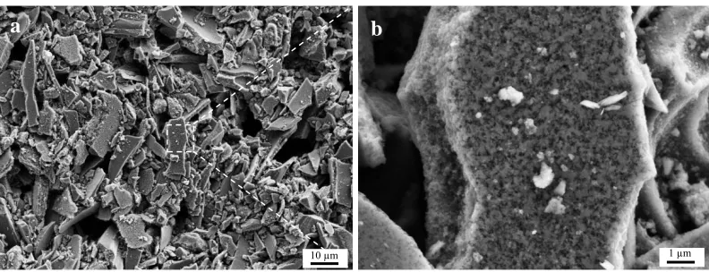
[image:3.596.100.496.435.587.2]Fig. 2(a) shows a scanning electron microscope (SEM) image of the active carbon material used in this study. It shows that the range of carbon particles size is from hundreds of nanometres to tens of microns. Fig. 2(b) further displays a magnified view of the carbon particle surface, which reveals the typical porous structure of the AC material. The average pore diameter is about 100 nm, which means that these porous structures should provide a large surface area for electrical charges to be stored.
Figure 2. (a) SEM images of the activated carbon electrode material, (b) Magnified porous surface of a carbon particle shown in (a).
The electrolyte was made from the tetrabutylammonium tetrafluoroborate (C16H36BF4N)
dissolved in propylene carbonate (C4H6O3). A solution of the electrolyte was dropped into the active
materials. The electrodes with the electrolyte imbibed were put in a vacuum desiccator at room temperature for 0.5 hours to allow the electrolyte to fully access the porous structures of the AC material. Meanwhile, the filter paper as a separator was also fully wetted with the electrolyte. Finally, the two electrodes separated by the separator were pushed together to make a sandwich which was
Stainless steel
Spacer
Activated carbon
Separator 3 mm
a
10 µm
b
then sealed together using a laminator filled with plastic laminating pouches to make a complete strip supercapacitor and to make it sealed against loss of electrolyte.
2.2 Measurement of the electrochemical performance
A galvanostatic charge-discharge test is widely used for the performance evaluation of supercapacitors. In the test process, a supercapacitor will be charged at a constant current, and then discharged over a specific voltage range or over certain discharge time. The capacitance, , can be calculated as
(1)
Where is the discharge current (A), is the discharge voltage (V) and is the scanning time in seconds.
And, the specific capacitance can be calculated as follows:
(2)
Where Cs is the specific capacitance of the electrode (F.g-1), C is the capacitance calculated
from equation (1), m is the average mass of activated carbon in each electrode.
2.3 Experimental Design
The JMP™ software, a tool for the design of experiments (DOE), can offer a practical approach for exploring multifactor experimental conditions. Some interacting factors may also be detected and a set of models can be developed to find the optimal conditions for the maximum output performance of the tested set of specimens. In this study, JMP™ was used to design the experimental conditions of the most expected significant parameters for EDLCs, which included the thickness (µm) of the AC slurry, the electrolyte concentration (mol/L), and the content (wt.%) of the CMC binder (based on the total mass of CMC and AC). The ranges of these three factors were set at 125 µm to 625 µm for the AC slurry thickness, 0.5 mol/L to 1.5 mol/L for the electrolyte concentration and 1% to 8% for the CMC content, which had been determined by a large number of initial experimental studies.
3. RESULTS AND DISCUSSION
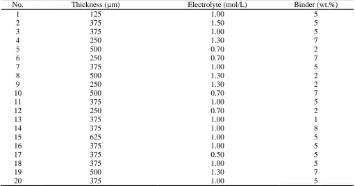
Table 1. Experiment parameters calculated by JMP.
No. Thickness (µm) Electrolyte (mol/L) Binder (wt.%)
1 125 1.00 5
2 375 1.50 5
3 375 1.00 5
4 250 1.30 7
5 500 0.70 2
6 250 0.70 7
7 375 1.00 5
8 500 1.30 2
9 250 1.30 2
10 500 0.70 7
11 375 1.00 5
12 250 0.70 2
13 375 1.00 1
14 375 1.00 8
15 625 1.00 5
16 375 1.00 5
17 375 0.50 5
18 375 1.00 5
19 500 1.30 7
20 375 1.00 5
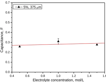
3.1 Effect of the electrolyte concentration
Previous research has indicated that the electrolyte concentration had an obvious effect on capacitance of a supercapacitor [20]. The electrolyte species and concentration are two main factors for electrolyte. In our work, the tetrabutylammonium tetrafluoroborate (C16H36BF4N) dissolved in
propylene carbonate (C4H6O3) was used as the electrolyte, so that the working potential can reach 2.4
0.4 0.6 0.8 1.0 1.2 1.4 1.6
0.0 0.1 0.2 0.3 0.4 0.5 0.6 0.7
C
ap
aci
tan
ce,
F
Electrolyte concentration, mol/L
[image:6.596.193.402.76.237.2]5%, 375 m
Figure 3. The effect of the electrolyte concentration on the capacitance of EDLCs.
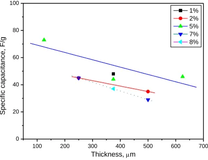
3.2 Effect of the thickness of the AC material layer
0 100 200 300 400 500 600 700
0.0 0.1 0.2 0.3 0.4 0.5 0.6 0.7 1% 2% 5% 7% 8% C ap aci tan ce, F
[image:7.596.183.412.76.247.2]Thickness, m
Figure 4. The effect of the thickness of activated carbon electrode layer on the capacitance of EDLCs.
0 100 200 300 400 500 600 700
0.000 0.005 0.010 0.015 0.020 0.025 0.030 1% 2% 5% 7% 8% M ass of A C i
n each el
ectr
od
e,
g
[image:7.596.182.414.320.489.2]Thickness, m
Figure 5. The relationship between the mass of AC in each electrode and thickness of activated carbon electrode layer.
100 200 300 400 500 600 700
0 20 40 60 80 100 1% 2% 5% 7% 8% S pe ci fi c cap aci tan ce, F/g Thickness, m
[image:7.596.194.404.547.708.2]
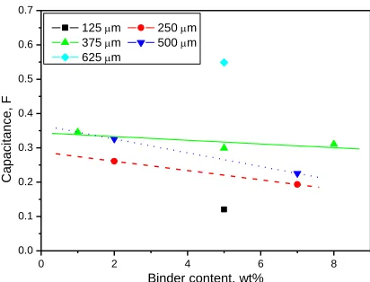
3.3 Effect of the content of the CMC binder
A binder in the electrode layer can hold the carbon particles together to forming a compacted active layer, and further let these electrode materials adhere onto the current collector. As an important material which was part of electrode, the binder content as the third main factor was studied in this work. Fig. 7 shows the effect of the binder content on capacitance with different thicknesses of AC slurry. It can be seen that in general the capacitance of the strip EDLCs with the same thickness of active layer decreased when the binder content increased. Take the EDLCs with the active layer thickness of 500 µm for example, when CMC binder content increased from 2% to 7%, the capacitance decreased dramatically from 0.326 F to 0.226 F. This is probably because the increases in concentration of CMC would block more pores or cover the surface of the AC particles resulting in reducing the effective specific surface area for adsorption of the electrolyte. Similar results were present in other carbon based supercapacitors [18,19], in particular, Richner et al. proved that the specific surface area of the active layer certainly decreased when the binder content increased (as measured by the BET method) [19]. Consequently, the capacitance of the EDLCs decreased when the content of binder increased.
0 2 4 6 8
0.0 0.1 0.2 0.3 0.4 0.5 0.6 0.7
C
ap
aci
tan
ce,
F
Binder content, wt%
[image:8.596.195.401.360.517.2]125 m 250 m 375 m 500 m 625 m
Figure 7. The effect of binder content on the capacitance of EDLCs.
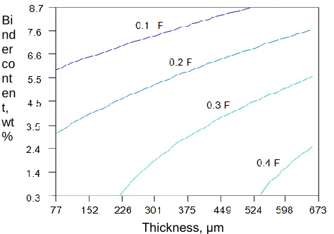
3.4 Experimental design results
[image:9.596.166.403.145.311.2]
experimental design results were consistent with the experimental results analysed and discussed in Fig. 3, Fig. 4 and Fig. 7.
Figure 8. The results of JMP optimisation for three parameters (Note the electrolyte concentration was not shown on the graph due to its ignorable effect).
4. CONCLUSIONS
Strip EDLCs (3 mm×100 mm) were successfully designed, fabricated and characterised in this study. The AC material was porous with an average size of the holes of about 100 nm, which allowed a good electrolyte accessibility to the inner surface of porous electrode and further provided a large surface area for electrical charge storage. Furthermore, the relationships between the performance and the key factors of the strip EDLCs including the CMC binder content, the electrolyte concentration and the thickness of active material layer were presented. There were no significant interactions found between the factors and therefore the factors were treated as being independent. The results showed that in the range of 0.5-1.5 mol/L, the electrolyte concentration had little effect on the capacitance; when the thickness of activated carbon electrode layer increased from 125 µm to 625 µm, the capacitance increased; and the capacitance decreased when the binder content increased from 1% to 8%.
ACKNOWLEDGEMENTS
This work was supported by the European Union Seventh Framework Programme (FP7/2007-2013) under grant agreement no. 281063.
References
1. R. Kötz, M. Carlen, Electrochim. Acta, 45 (2000) 2483-2498. 2. J. R. Miller, P. Simon, Science, 321 (2008) 651-652.
3. J. Gamby, P. L. Taberna, P. Simon, J. F. Fauvarque and M. Chesneau, J. Power Sources, 101 (2001) 109-116.
Bi nd er co nt en t, wt %
4. M. Jayalakshmi, K. Balasubramanian, Int. J. Electrochem. Sci., 3 (2008) 1196-1217. 5. E. Frackowiak, Q. Abbas and F. Béguin, J. Energy Chem., 22 (2013) 226-240.
6. S. Chen, R. Ramachandran, V. Mani and R. Saraswathi, Int. J. Electrochem. Sci., 9 (2014) 4072-4085.
7. Y. Zhang, H. Feng, X. Wu, L. Wang, A. Zhang, T. Xia, H. Dong, X. Li and L. Zhang, Int. J. Hydrogen Energy, 34 (2009) 4889-4899.
8. D. Qu, J. Power Sources, 109 (2002) 403-411.
9. H. Shen, E. Liu, X. Xiang, Z. Huang, Y. Tian, Y. Wu, Z. Wu and H. Xie, Mater. Res. Bull., 47 (2012) 662-666.
10.J. Jiang, A. Kucernak, Electrochim. Acta, 47 (2002) 2381-2386.
11.H. Gómez, M. K. Ram, F. Alvi, P. Villalba, E. Stefanakos and A. Kumar, J. Power Sources, 196 (2011) 4102-4108.
12.H. Gómez, M. K. Ram, F. Alvi, P. Villalba, E. Stefanakos and A. Kumar, J. Power Sources, 196 (2011) 4102-4108.
13.F. Lufrano, P. Staiti. International Journal of electrochemical science, 5 (2010) 903-916. 14.O. Barbieri, M. Hahn, A. Herzog and R. Kötz, Carbon, 43 (2005) 1303-1310.
15.J. H. Kim, Y. S. Lee, A. K. Sharma and C. G. Liu, Electrochim. Acta, 52 (2006) 1727-1732. 16.H. Shi, Electrochimica Acta. 41 (1996) 1633-1639.
17.J. Sánchez-Gonzáleza, F. Stoecklib, T. A. Centeno. Journal of electroanalytical Chemistry 657 (2011) 176-180.
18.K. C. Tsay, L. Zhang and J. Zhang, Electrochim. Acta, 60 (2012) 428-436.
19.R. Richner, S. Müller, M. Bärtschi, R. Kötz and A. Wokaun, J. New Mater. Electrochem. Syst. 5 (2002) 297-303.
20.J. P. Zheng, T. R. Jow. J. Electrochem. Soc. 144 (1997) 2417-2420.
21.S. Kumagai, K. Mukaiyachi, D. Tashima. J. Energy Storage 3 (2015) 10-17.