1
-Microprocessor
7
10
3
ICT
and
Interfacing
Lecture Notes # 18 Outline of the Lecture
• Interfacing the Parallel Port
♦ Standard Parallel Port (SPP) ♦ Port addresses
♦ Software registers and programming ♦ Bi-directional ports
♦ Using parallel port’s IRQ ♦ Enhanced Parallel Port (EPP) ♦ Extended Capabilities Port (ECP)
•
Standard Parallel Port
¾ The Parallel Port is the most commonly used port for interfacing. This port will allow the input of up to 9 bits or the output of 12 bits at any one given time, thus requiring
minimal external circuitry to implement many simpler tasks.
¾ It's found commonly on the back of your PC as a D-Type 25 Pin female connector. Parallel Port’s are standardized under the IEEE 1284 standard first released in 1994. This standard defines 5 modes of operation which are as follows,
¾
1. Compatibility Mode. (Centronics Mode) 2. Nibble Mode.
3. Byte Mode.
4. EPP Mode (Enhanced Parallel Port). 5. ECP Mode (Extended Capabilities Mode).
¾ Compatibility mode is also known as "Centronics Mode". In this mode you can only output data.
¾ To receive/input data, you must change the mode to either Nibble or Byte mode. Nibble mode can input a nibble (4 bits) from device to computer.
¾ Byte mode uses the Parallel's bi-directional feature (found only on some cards) to input a byte (8 bits) of data.
¾ Extended and Enhanced Parallel Ports use additional hardware to generate and manage handshaking.
¾ For example, to output a byte to a printer (or anything in that matter) using compatibility mode, the software must,
1. Write the byte to the Data Port.
2. Check to see is the printer is busy. If the printer is busy, it will not accept any data, thus any data which is written will be lost.
3. Take the Strobe (Pin 1) low. This tells the printer that there is the correct data on the data lines/pins (Pins 2-9).
4. Put the strobe high again after waiting approximately 5 microseconds after putting the strobe low. (Step 3)
2 megabytes per second. The ECP port also has the advantage of using DMA channels and FIFO buffers, thus data can be shifted around without using I/O instructions.
•
Port Addresses
The Parallel Port has three commonly used base addresses. LPT1 is normally assigned base address 378h, while LPT2 is assigned 278h. 378h & 278h have always been
commonly used for Parallel Ports.
Address Notes:
3BCH - 3BFH Used for Parallel Ports which were incorporated on to Video Cards - Doesn't support ECP addresses
[image:2.612.82.532.365.711.2]378H - 37FH Usual Address For LPT 1 278H - 27FH Usual Address For LPT 2
Table 2 Port Addresses
•
Hardware Properties
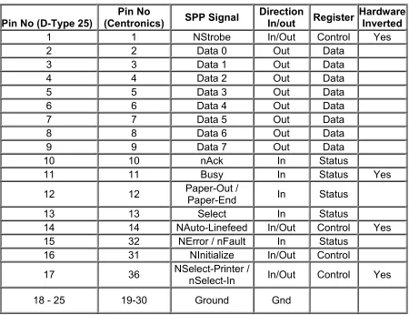
¾ Below is a table of the "Pin Outs" of the D-Type 25 Pin connector and the Centronics 34 Pin connector. The D-Type 25 pin connector is the most common connector found on the Parallel Port of the computer, while the Centronics Connector is commonly found on printers.
Pin No (D-Type 25) (Centronics)Pin No SPP Signal Direction In/out Register Hardware Inverted
1 1 NStrobe In/Out Control Yes
2 2 Data 0 Out Data
3 3 Data 1 Out Data
4 4 Data 2 Out Data
5 5 Data 3 Out Data
6 6 Data 4 Out Data
7 7 Data 5 Out Data
8 8 Data 6 Out Data
9 9 Data 7 Out Data
10 10 nAck In Status
11 11 Busy In Status Yes
12 12 Paper-Out / Paper-End In Status
13 13 Select In Status
14 14 NAuto-Linefeed In/Out Control Yes
15 32 NError / nFault In Status
16 31 NInitialize In/Out Control
17 36 NSelect-Printer / nSelect-In In/Out Control Yes
18 - 25 19-30 Ground Gnd
3 ¾ The above table uses "n" in front of the signal name to denote that the signal is active
low. e.g. nError. If the printer has occurred error then this line is low.
¾ The "Hardware Inverted" means the signal is inverted by the Parallel card's hardware. Such an example is the Busy line. If +5v (Logic 1) was applied to this pin and the status register read, it would return back a 0 in Bit 7 of the Status Register.
¾ The output of the Parallel Port is normally TTL logic levels. The voltage levels are the easy part. The current you can sink and source varies from port to port. Most Parallel Ports can sink and source around 12mA. The best way is to use a buffer, so the least current is drawn from the Parallel Port.
•
Centronics?
¾ Centronics is an early standard for transferring data from a host to the printer. The majority of printers use this handshake. This handshake is normally implemented using a Standard Parallel Port under software control.
•
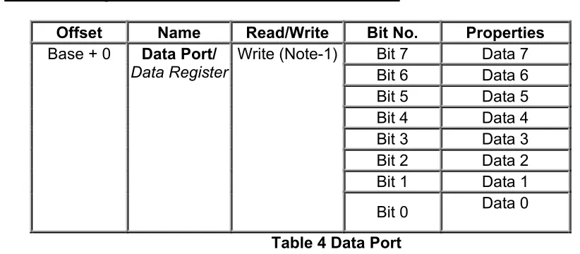
Software Registers - Standard Parallel Port (SPP)
Offset Name Read/Write Bit No. Properties
Bit 7 Data 7
Bit 6 Data 6
Bit 5 Data 5
Bit 4 Data 4
Bit 3 Data 3
Bit 2 Data 2
Bit 1 Data 1
Base + 0 Data Port/
DataRegister Write (Note-1)
[image:3.612.93.504.318.498.2]Bit 0 Data 0
Table 4 Data Port
¾ Note 1 : If the Port is Bi-Directional then Read and Write Operations can be performed on the Data Register.
4 Offset Name Read/Write Bit No. Properties
Bit 7 Busy
Bit 6 Ack
Bit 5 Paper Out Bit 4 Select In
Bit 3 Error
Bit 2 IRQ (Not) Bit 1 Reserved Base + 1 Status Port/
Status Register
Read Only
[image:4.612.122.493.65.230.2]Bit 0 Reserved
Table 5 Status Port
¾ The Status Port (base address + 1) is a read only port. Any data written to this port will be ignored. The Status Port is made up of 5 input lines (Pins 10,11,12,13 & 15), an IRQ status register and two reserved bits.
Offset Name Read/Write Bit No. Properties
Bit 7 Unused
Bit 6 Unused
Bit 5 Enable Bi-Directional Port Bit 4 Enable IRQ Via Ack Line Bit 3 Select Printer Bit 2 Initialize Printer (Reset) Bit 1 Auto Linefeed Base + 2 Control Port/
Control Register
Read/Write
Bit 0 Strobe
Table 6 Control Port
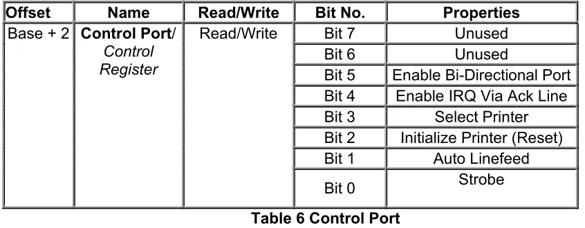
¾ The Control Port (base address + 2) was intended as a write only port. When a printer is attached to the Parallel Port, four "controls" are used. These are Strobe, Auto Linefeed, Initialize and Select Printer, all of which are inverted except Initialize.
•
Bi-directional Ports
¾ Bit 5 of the Control Port enables or disables the bi-directional function of the Parallel Port. This is only available on true bi-directional ports. When this bit is set to one, pins 2 to 9 go into high impedance state. Once in this state you can enter data on these lines and retrieve it from the Data Port (base address). Any data which is written to the data port will be stored but will not be available at the data pins. To turn off bi-directional mode, set bit 5 of the Control Port to '0'.
[image:4.612.96.519.308.473.2]5
•
Using The Parallel Port to Input 8 Bits.
If your Parallel Port doesn't support bi-directional mode, don't despair. You can input a maximum of 9 bits at any one given time. To do this you can use the 5 input lines of the Status Port and the 4 inputs (open collector) lines of the Control Port.
¾ In order to input 8-bit input data we input data both from status port and control port. The high nibble of status port and low nibble of the control port are combined to make an 8-bit input data.
•
Using the Parallel Port's IRQ
¾ The Parallel Port's interrupt request is not used for printing under DOS or Windows. Early versions of OS-2 used them, but don't anymore. Interrupts are good when interfacing monitoring devices such as high temp alarms etc, where you don't know when it is going to be activated. It's more efficient to have an interrupt request rather than have the software poll the ports regularly to see if something has changed. This is even more noticeable if you are using your computer for other tasks, such as with a multitasking operating system.
¾ The Parallel Port's interrupt request is normally IRQ5 or IRQ7 but may be
something else if these are in use. It may also be possible that the interrupts are totally disabled on the card, if the card was only used for printing.
¾ The Parallel Port interrupt can be disabled and enabled using bit 4 of the control register, Enable IRQ Via Ack Line. Once enabled, an interrupt will occur upon a low to high transition (rising edge) of the nACK. However like always, some cards may trigger the interrupt on the high to low transition.
6
•
Programming of the Parallel Port
Ex1: Write required Assembly Language instructions to output 11111111B to the Data Port of the SPP?
MOV DX,378H ;base address of SPP is 378H
MOV AL,11111111B ;Data Port is placed at [base address + 0]
OUT DX,AL
Ex2: Write required Assembly Language instructions to check if the Paper has run out at the printer (paper out).
Bit 5 of the Status port indicates the status of paper at the Printer. So after inputting 8-bit data from this port at [base address+1] we can check if paper is finished or not.
MOV DX,378H ;base address of SPP is 378H
INC DX ;[378H+1]
IN AL,DX AND AL,00100000B CMP AL,00100000B JE OVER
CALL PAPER_OK ;a procedure to report that paper is ok! JMP OVER2
OVER: CALL PAPER_OUT ;a procedure to report that paper is run out OVER2:
•
EPP - Enhanced Parallel Port
¾ The Enhanced Parallel Port (EPP) was designed in a joint venture between Intel, Xircom & Zenith Data Systems. EPP Ports were first specified in the EPP 1.7 standard, and then later included in the IEEE 1284 Standard released in 1994. EPP has two standards, EPP 1.7 and EPP 1.9. There are differences between the two standards which may affect the operation of devices. This is further discussed latter. EPP has a typical transfer rate in the order of 500KB/S to 2MB/S. This is achieved by allowing the hardware contained in the port to generate handshaking, strobing etc, rather that have the software do it, which was the case with Centronics.
¾ EPP is more commonly used than ECP. EPP differs from ECP by the fact that the EPP Port generates and controls all the transfers to and from the peripheral. ECP on the other hand requires the peripheral to negotiate a reverse channel and control the handshaking. This is harder to achieve, thus really requires a dedicated
controller or ECP Peripheral Chip.
•
(ECP) Extended Capabilities Port
7 channels to move it's data about. It also uses a FIFO buffer for the sending and/or receiving of data.
¾ Another feature of ECP is a real time data compression. It uses Run Length Encoding (RLE) to achieve data compression ratio's up to 64:1. This comes is useful with devices such as Scanners and Printers where a good part of the data is long strings which are repetitive.
¾ The Extended Capabilities Port supports a method of channel addressing. This is not intended to be used to daisy chain devices up but rather to address multiple devices within one device. Such an example is many fax machines on the market today which may contain a Parallel Port to interface it to your computer. The fax machine can be split up into separate devices such as the scanner, modem/Fax and printer, where each part can be addresses separately, even if the other devices cannot accept data due to full buffers.
REFENENCE:
Read, http://www.beyondlogic.org/spp/parallel.htm ,for further details.