Al-Hanafy, Waleed and Weiss, S. (2010) Greedy power allocation for multicarrier systems with reduced
complexity. In: The 27th National Radio Science Conference, NRSC 2010, 16-18 March 2010, Menouf,
Egypt.
http://strathprints.strath.ac.uk/
27156
/
Strathprints is designed to allow users to access the research output of the University of
Strathclyde. Copyright © and Moral Rights for the papers on this site are retained by the
individual authors and/or other copyright owners. You may not engage in further
distribution of the material for any profitmaking activities or any commercial gain. You
may freely distribute both the url (
http://strathprints.strath.ac.uk
) and the content of this
paper for research or study, educational, or not-for-profit purposes without prior
permission or charge. You may freely distribute the url (
http://strathprints.strath.ac.uk
)
of the Strathprints website.
Greedy Power Allocation for Multicarrier Systems with Reduced
Complexity
Waleed Al-Hanafy
?‡and Stephan Weiss
??Centre for Excellence in Signal & Image Processing, Dept. of EEE, Univ. of Strathclyde, Glasgow, Scotland, UK
‡Electronics & Comm. Eng. Dept., Faculty of Electronic Engineering, Menoufia Univ., Menouf, Egypt
Abstract
In this paper we consider a reduced complexity discrete bit loading for Multicarrier systems based on the greedy power allocation (GPA) under the constraints of transmit power budget, target BER, and maximum permissible QAM modulation order. Compared to the standard GPA, which is optimal in terms of maximising the data throughput, three suboptimal schemes are proposed, which perform GPA on subsets of subcarriers only. These subsets are created by considering the minimum SNR boundaries of QAM levels for a given BER. We demonstrate how these schemes can reduce complexity. Two of the proposed algorithms can achieve near optimal performance by including a transfer of residual power between groups at the expense of a very small extra cost. It is shown that the two near optimal schemes, while greatly reducing complexity, perform best in two separate and distinct SNR regions.
1
Introduction
In OFDM, or general transmultiplexing techniques a number of independent subcarriers arise for transmission, which differ in SNR. Maximising the channel capacity or data throughput under the constraint of limited transmit power leads to the well-known and simple waterfilling algorithm [1]. Waterfilling is generally followed by bit loading, where
bibits are allocated to the QAM symbols transmitted over the ith subcarrier. To achieve an identical target bit error ratio (BER) across all subcarriers leads to bi∈R, which needs to be rounded off to the nearest integer b(ir)=bbic, thus
lowering the overall throughput. Furthermore, unbounded modulation orders b(ir)→∞in the case of infinite SNR are required to efficiently utilise the transmit power but are practically unfeasible.
Pure waterfilling-based solutions have been reported in [2, 3, 4], leading to some of the above stated problems. Reallocation of the excess power when realising the target BER given b(ir)∈Zand the SNR in the ith subcarrier has lead to a rate-optimal algorithm known as the greedy algorithm [5, 6], of which a number of difference variation have emerged constraining the average BER [7] or the total power [8]. For a good review of greedy algorithms, please refer to [9].
While achieving rate optimality, the family of greedy algorithms is also known to be greedy in terms of computing requirements. Therefore, reduced complexity schemes are either waterfilling-based only [2] or aim at simplifica-tions [10]. Different from our previous work of MIMO sum-rate maximisation presented in [11, 12], the interest of this paper is focusing on OFDM Multicarrier systems to more elaborate on complexity reduction especially for higher numbers of subcarriers. A novel suboptimal greedy algorithm is proposed, whereby the power re-allocation is performed in subsets of the subcarriers. We show that some simple overall redistribution can be included at very low cost, whereby two different methods on terms of approximate overall optimisation are discussed. These subop-timal schemes, while greatly reducing complexity, are hardly sacrifice any performance compared to the full greedy algorithm, provided that the correct algorithmic version is applied for specific SNR regions.
2
Greedy Approach Review
2.1
Problem Statement
We consider the problem of maximising the transmission rate over an OFDM Multicarrier system. A single-input single-output (SISO) OFDM system, whereby the ISI channel characterised by a FIR vector h= [h0···hL]∈CL+1 of order L is converted into an N-subcarrier system with different gains gi,i=1···N. The extension to the MIMO OFDM case is straightforward. The ith subcarrier experiencing the gain giwill be used to transmit bibits per symbol. Maximising the sum-rate
max N
∑
i=1
bi, (1)
with total power budget, target bit error ratio (BER), and maximum permissible QAM modulation order constraints can be formulated as
N
∑
i=1
Pi≤Pbudget, Pb,i=Pbtarget and bi≤bmax,∀i (2)
where Pi is the amount of power allocated to the ith subcarrier to achieve a BERPb,i, and bmax is the maximum number of permissible allocated bits per subcarrier. Note that BERs are assumed equal, i.e.Pb,i=Ptarget
b in (2) for all subcarriers i=1···N and therefore the subscript i will be dropped from the BER notation.
The carrier-to-noise ratio of the ith subcarrier can be defined as
CNRi=
g2
i
N0, (3)
whereN0is the total noise power at the receiver, whereas the SNR of this subcarrier is
γi=Pi×CNRi. (4)
For BPSK modulation, BER can be related to the subcarrier SNRγiasPb=Q(√2γi), while for rectangular M-QAM modulation of order Mk, BER is given by [13]
Pb=
1−h1−21−√1M
k
Qq 3γi Mk−1
i2
log2Mk
. (5)
Therefore, symbols of bk-bits, bk=log2Mkcan be loaded to a subcarrier with minimum required SNR obtained from (5) as
γQAM
k =
Mk−1 3
"
Q−1 1−
p
1−Pblog2Mk
2 1−1/√Mk
!#2
, (6)
where Q−1is the inverse of the well-known Q function, Q(x) =√1 2π
R∞
x e−u 2/2
du.
The problem is solved in two steps, (i) a uniform power allocation (UPA) initialisation step and (ii) the Greedy algorithm, both described below.
2.2
UPA Algorithm and Initialisation Setup
The uniform power allocation is performed by the following steps:
1. CalculateγkQAMfor all Mk,1≤k≤K andPb=Pbtargetusing (6), where MKis the maximum QAM constellation that is potentially permissible by the transmission system, i.e., MK=2b
max .
2. Equally allocate Pbudgetamong all subcarriers 1≤i≤N
γi=Pi×CNRi=
Pbudget
3. Reside subcarriers according to their SNRγiinto QAM groups Gk,0≤k≤K bounded by QAM levelsγkQAM andγkQAM+1 withγ0QAM=0 andγKQAM+1 = +∞(cf. Fig. 1) such that
γi≥γkQAM and γi<γkQAM+1 . (8)
4. For each group Gk, load subcarriers within this group with QAM constellation Mkand compute the group’s total allocated bits
Buk=
∑
i∈Gk
bui,k=
∑
i∈Gk
log2Mk (9)
with Bu0=0. It is clear at this point and from step (3) that subcarriers are resided into QAM groups of SNR levels that is less than their original SNRs;γkQAM≤γiand therefore leaving some unused (excess) power of
Pkex = ∑i∈Gk
γi−γkQAM
CNRi =∑i∈GkPi−
γQAM k
CNRi.
(10)
5. The overall system allocated bits and used power for the uniform power allocation scheme are therefore,
Bu= K
∑
k=1
Buk (11a)
Puused=Pbudget−
K
∑
k=0
Pkex=Pbudget−Pex, (11b)
where Pexis the overall excess power missed by the UPA scheme. Note that the summation in (11a) starts from group G1since none of the subcarriers in G0will be loaded in this initialisation.
0 5 10 15 20 25 30
0 50 100 150 200
original subcarrier indices
subcarriers SNRs
0 5 10 15 20 25 30
0 50 100 150 200
ordered subcarrier indices
γ3QAM γ4QAM γ5
[image:4.612.114.519.361.486.2]QAM γ6QAM
Figure 1: An illustrative example for grouping subcarriers of a 32-subcarrier system of SNR = 25 dB and
Ptarget
b =10−3with bmax=6 bits.
It is clear from (11b) that Pex
k has an obvious impact on the performance of the UPA scheme. The worst cases are
P0ex and PKex which reveal inefficient power allocations in situations of low-to-medium and medium-to-high SNRs, respectively, as will be discussed in Sec. 5.
2.3
Full Greedy Power Allocation (GPA) Algorithm
Based on the initialisation step described in the previous section, the full GPA algorithm [8] performs an iterative re-distribution of the unallocated power of the UPA algorithm Pexby applying the algorithmic steps detailed in Table 1. At each iteration, this algorithm tries to increase bit loading by upgrading (to the next higher QAM level) the subcarrier of the least power requirements through an exhaustive search, step (4) in Table 1 for all subcarriers N. When either of the following events occurred: i) the remaining power cannot afford any further upgrades or ii) all subcarriers appear in the highest QAM level K, the algorithm stops resulting in an overall system allocated bits
Bgpa=
N
∑
i=1
Table 1: Full GPA algorithm applied to the initialisation step of the UPA algorithm
Initialisation:
1. Set power available for GPA to Pagpa=Pexin (11b)
For each subcarrier i do the following: 2. Set bgpai =bui in (9) and index ki=k in (8)
3. Cal. the min required upgrade power: Piup=γ
QAM
ki+1−γ QAM
ki
CNRi
Recursion:
while Pagpa≥min(Piup)and min(ki)<K, 1≤i≤N
4. j=argmin
1≤i≤N
(Piup)
5. kj=kj+1, Pagpa=Pagpa−Pupj
if kj=1
6. bgpaj =log2M1, Pupj =
γQAM
k j+1−γ QAM
k j
CNRj
elseif kj<K
7. bgpaj =bgpaj +log2MMk j k j−1
, Pupj =γ
QAM
k j+1−γ QAM
k j
CNRj
else
8. bgpaj =bgpaj +log2
Mk j Mk j−1
, Pupj = +∞ end
end
3
Proposed Low-Cost GPA
Given Bukas defined in (9) and Pkexin (10), three low-cost greedy algorithms are proposed to efficiently utilise the total excess power of the uniform power allocation in (11b) using the QAM grouping concept. More precisely, GPA is separately accomplished for each QAM group Gkaiming to increase the total bit allocation to this group and therefore the overall system allocated bits. Based on the way of making use of Pkex, we propose three different algorithms, which below are referred to as (i) grouped GPA (g-GPA), (ii) power up GPA (Mu-GPA) and (iii) power Moving-down GPA (Md-GPA).
3.1
g-GPA Algorithm
As discussed in Sec. 2, optimum discrete bit loading with total power and maximum permissible QAM order constraints can be performed by the GPA approach. However, the direct application of GPA is computationally very costly due to the fact that at each simulation iteration an exhaustive sorting of all subcarriers is required as evident from Table 1.
A simplification of GPA can be achieved if subcarriers are firstly divided into QAM groups Gk,0≤k≤K according to their SNRs as shown in Fig. 1, where we assume a Multicarrier systems with subcarriers not ordered with respect to their SNR yet. GPA is therefore independently applied to each group Gk, trying to allocate as much of the excess power Pkexwithin this QAM group. This excess power is iteratively allocated to subcarriers within this group according to the greedy concept with the aim of upgrading as many subcarriers as possible to the next QAM level.
The pseudo code for the kth QAM group Gkof the g-GPA algorithm is given in Table 2. Note that different from the standard GPA, this algorithm permits upgrades to the next QAM level only for a given QAM group (Pupj is set to
+∞in steps (5) and (6) in Table 2) and therefore may leave some left-over (LO) power PLO
k for each QAM group Gk, resulting in a total left-over power of
PgLO=
K−1
∑
k=0
PkLO+PKex. (13)
Intuitively, for the overall performance of the g-GPA algorithm, the algorithm in Table 2 has to be executed K times, one for each QAM group, from G0to GK−1resulting in an overall system that allocated bits given by
Bg=
K−1
∑
k=0
Table 2: g-GPA algorithm for subcarriers in the kth QAM group Gk
Input: bui,k, Pkex,γdQAM,k =γkQAM+1 −γkQAM, CNRi Output: B
g
k, P
LO
k
1. ∀i∈Gk, cal. the min required upgrade power: Piup=
γQAM
d,k
CNRi 2. Initiate bgi,k=biu,kand PkLO=Pkex
while PkLO≥min(Piup)
3. j=argmin
i∈Gk
(Piup)
4. PkLO=PkLO−Pupj
if k=0
5. bgj,k=log2M1, Pupj = +∞
else
6. bgj,k=bgj,k+log2MMk+k1, P
up
j = +∞
end end
7. Bgk= ∑
i∈Gk
bgi,k
3.2
Mu-GPA Algorithm
The g-GPA algorithm results in unused PkLOfor each QAM group. This residual power can be exploited by a second stage, whereby it is proposed to move power upwards starting from the lowest QAM group, as outlined in Fig. 2(a). This modifies the g-GPA algorithm by considering the left-over power P0LOof the QAM group G0after running the
g-GPA algorithm on that group , and assign this power for redistribution to group G1. Any left-over power after
running g-GPA on G1is then passed further upwards to G2, and so forth. At the kth algorithmic iteration, the
Mu-GPA algorithm is working with Gkand tries to allocate the sum of the excess power missed by the UPA algorithm of that group as well as the left-over power of the application of the g-GPA algorithm to the previous group Gk−1, i.e.,
Pkex+PkLO−1(cf. Fig. 2(a)). Finally, the left-over power resulting from the QAM group GK−1is added to the excess
power of the KthQAM group PKexto end up with a final left-over power
PMuLO−g=PKLO−1+PKex (15)
and overall system allocated bits
BMu−g=
K−1
∑
k=0
BMuk −g+BuK. (16)
Final
left-Group G0 PLO
0 Group G1 PLO 1 Pex 0 ··· PLO
K−1
Group GK−1 Pex 1 Pex 2 Pex K g-GPA Algorithm g-GPA Algorithm g-GPA Algorithm over power Left-over power transfer direction (a) PLO K−1 Pex K−1
PKex−2 PKex
···
Pex 0
Group G0
g-GPA Algorithm g-GPA Algorithm g-GPA Algorithm Left-over power transfer direction Final left-over power Group GK−2
Group GK−1
P0LO PLO
K−2
(b)
[image:6.612.75.543.431.672.2]3.3
Md-GPA Algorithm
A second algorithm is proposed to exploit the residual power PkLO of each QAM group but in a reverse direction compared to the Mu-GPA algorithm, starting from the highest-indexed QAM group GK−1downwards to the
least-index QAM group G0. This procedures is illustrated in Fig. 2(b) which show the direction of the left-over power
flow. Proceeding downwards, at the kth stage this algorithm applies the g-GPA algorithm for the available power that comprises both the excess power missed by the UPA algorithm of the previous QAM group (Gk+1in this case) and the left-over power of the previous stage, i.e., Pex
k+1+PkLO+1, as also characterised in Fig. 2(b). Therefore, the excess power
of the QAM group under consideration is not utilised within this group but is transferred to the next working group along with the left-over power of the former QAM group. This will finally results in a left-over power of
PMdLO−g=P0LO+P0ex, (17)
and overall system allocated bits
BMd−g=
K−1
∑
k=0
BMdk −g+BuK. (18)
4
Complexity Evaluation
Instead of jointly applying GPA algorithm across all subcarriers which consequently requires high system complexity especially for large numbers of subcarriers, the g-GPA algorithm only addresses a subset of subcarriers within a specific QAM group at a time. Beyond the division of the QAM grouping concept, a further reduction in complexity can be achieved if subcarriers are initially ordered in their gains CNRi(see Fig. 1). In this case the search step (3) in Table 2 can be replaced by a simple incremental indexing.
[image:7.612.110.504.413.453.2]Referring to Table 1 and Table 2 the computational complexity of both GPA and g-GPA algorithms is summarised in Table 3, whereby the no. of operations is computed for each algorithm. Both subcarriers “no order” and “order”
Table 3: Computational analysis for both GPA and g-GPA algorithms
algorithm GPA (order and no order) g-GPA (no order) g-GPA (order) no. of operations L1(2N+7) +4N+1 α[L2(2β+4) +2β+2] α[L2(β+5) +2β+2]
≈K
L2(2NK +4) + 2N
K +2
≈K
L2(NK+5) + 2N
K +2
cases are considered. Note that for the GPA algorithm ordering subcarriers does not lead to any improvement in complexity as the search step (4) in the while loop has to include all subcarriers. This is due to the fact — which represents the core idea behind this work — that by relaxing the grouping concept it is possible to find subcarriers in lower QAM levels that need less power to upgrade than others in higher QAM levels. The quantities L1and L2
in Table 3 denote the no. of iterations of the while loops for the GPA (Table 1) and the g-GPA (Table 2) algorithms, respectively. For the g-GPA algorithmα andβ stand, respectively, for the average no. of QAM groups occupied by all subcarriers N and the average no. of subcarriers per QAM group. Obviously,α andβ cannot be easily quantified as they both depend on CNRi, which is aχ2random variable, and the operating SNR, therefore the complexity of the g-GPA algorithm is assessed in a heuristic fashion. In the worst case and by assuming that subcarriers are uniformly distributed across all QAM groups, the g-GPA computational complexity is approximately given by the second line formula of Table 3 which is still less than its GPA counterpart.
5
Simulation Results and Discussion
Secs. 3.2 and 3.3 have shown that both Mu-GPA and Md-GPA algorithms work very similarly in utilising the left-over power PkLOfor all groups k,0≤k≤K−1 that remained unused by the g-GPA algorithm. The two algorithms differ in the direction in which PkLOis transferred. Below we compare the two algorithms with the UPA, GPA, and the g-GPA approaches.
Simulations are conducted for a SISO system of 6-tabs FIR, where the entries of the SISO channel h are drawn from complex Gaussian processes with zero-mean and unit-variance, i.e., hl∈C N (0,1). Results presented below refer to ensemble averages across 103channel realisations for target BERPtarget
using QAM modulation schemes Mk=2k,k=1···K with K =6 being the maximum permissible QAM level of constellation size MK=64 which is equivalent to encoding 6 bits per data symbol.
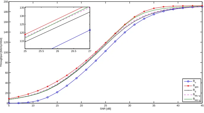
The total system throughput is examined and shown in Fig. 3 for all proposed algorithms in addition to both UPA and standard GPA algorithms. It is evident that UPA represents an inefficient way of bit loading since the performance is approximately 2 to 8 dB below other algorithms, and provide approximately half the throughput at 15 dB SNR.
5 10 15 20 25 30 35 40 45
0 20 40 60 80 100 120 140 160 180 200
SNR [dB]
Throughput [bits/symbol]
Bu B
gpa B
g BMu−g BMd−g
25 25.5 26 26.5 27
[image:8.612.135.480.157.348.2]115 120 125 130 135
Figure 3: Overall throughput for 32-subcarrier system withPtarget
b =10−
3.
Of the proposed reduced complexity greedy algorithms, both Mu-GPA and Md-GPA algorithms outperform the g-GPA without the refinement stage to allocate the residual power across QAM groups. Interestingly, Mu-g-GPA performs better at low SNR, while Md-GPA performs better at higher SNRs. This can be attributed to the fact that for low-to-medium SNRs PKex(which is missed by the Mu-GPA) in this case will be relatively low and can be allocated without violating the constraint on maximum QAM levels. While P0ex(which is missed by the Mg-GPA) is most likely to be high, please see (10) and Fig. 1. For medium-to-high SNRs PKex>P0excan be expected to be high, and then Md-GPA is likely to be advantageous in its bit allocation as PKexis fully utilised by the Md-GPA algorithm.
Finally, for very high SNRs most subcarriers will appear in the highest QAM group GK as their SNRs,γiin (7), exceed the highest QAM level γKQAM in (6). As a result, the overall system throughput of all different algorithms reaches its expected maximum.
In order to assess the computational complexity of the proposed scheme compared to the standard GPA algorithm, Fig. 4 shows the computation time against the no. of subcarriers N for the g-GPA algorithm with both “no order” and “order” cases compared to the GPA algorithm. Two different SNRs values of 15 and 35 dB that is suitable for the application of mobile and fixed wireless communication, respectively, are considered. It is clear that the g-GPA algorithm is much computationally efficient in particular for large values of N and SNRs, the effect of subcarriers ordering is also evident as discussed in Sec. 4.
6
Conclusions
0 200 400 600 800 1000 1200 0
1 2 3 4 5 6
no. of subcarriers
computation time [mSec.]
SNR = 15 dB
GPA g−GPA (no order) g−GPA (order)
0 200 400 600 800 1000 1200
0 5 10 15 20 25 30 35
no. of subcarriers SNR = 35 dB
[image:9.612.118.520.73.206.2]GPA g−GPA (no order) g−GPA (order)
Figure 4: Average computation time comparison of g-GPA and GPA algorithms.
hence no bits may be loaded with the excess power. However, in general both algorithms perform very close to the GPA in their respective domains of preferred operation, thus permitting to allocate power close to the performance of the GPA at a much reduced cost.
References
[1] D. Palomar and J. Fonollosa, “Practical Algorithms for a Family of Waterfilling Solutions,” IEEE Transactions on Signal
Processing, vol. 53, no. 2, pp. 686–695, Feb 2005.
[2] B. Krongold, K. Ramchandran, and D. Jones, “Computationally efficient optimal power allocation algorithms for multicarrier communication systems,” IEEE Transactions on Communications, vol. 48, no. 1, pp. 23–27, Jan 2000.
[3] E. Baccarelli, A. Fasano, and M. Biagi, “Novel Efficient Bit-Loading Algorithms for Peak-Energy-Limited ADSL-Type Multicarrier Systems,” IEEE Transactions on Signal Processing, vol. 50, no. 5, pp. 1237–1247, May 2002.
[4] X. Zhang and B. Ottersten, “Power Allocation and Bit Loading for Spatial Multiplexing in MIMO Systems,” in IEEE
Inter-national Conference on Acoustics, Speech, and Signal Processing, (ICASSP ’03), vol. 5, April 2003, pp. V–53–56.
[5] J. Campello, “Optimal Discrete Bit Loading for Multicarrier Modulation Systems,” in IEEE International Symposium on
Information Theory, Aug 1998, p. 193.
[6] ——, “Practical bit loading for DMT,” in IEEE International Conference on Communications, ICC ’99, vol. 2, 1999, pp. 801–805 vol.2.
[7] A. M. Wyglinski, F. Labeau, and P. Kabal, “Bit Loading with BER-Constraint for Multicarrier Systems,” IEEE Transactions
on Wireless Communications, vol. 4, no. 4, pp. 1383–1387, July 2005.
[8] L. Zeng, S. McGrath, and E. Cano, “Rate Maximization for Multiband OFDM Ultra Wideband Systems Using Adaptive Power and Bit Loading Algorithm,” in IEEE Fifth Advanced International Conference Telecommunications, AICT ’09, Ve-nice/Mestre, Italy, May 2009, pp. 369–374.
[9] N. Papandreou and T. Antonakopoulos, “Bit and Power Allocation in Constrained Multicarrier Systems: The Single-User Case,” EURASIP Journal on Advances in Signal Processing, vol. 2008, pp. 1–14, 2008.
[10] C. Assimakopoulos and F.-N. Pavlidou, “New bit loading algorithms for DMT systems based on the greedy approach,”
Wire-less Communications and Mobile Computing, vol. 6, no. 8, pp. 1047–1056, 2006.
[11] W. Al-Hanafy and S. Weiss, “A New Low-Cost Discrete Bit Loading using Greedy Power Allocation,” in The Third
Mosha-raka International Conference on Communications, Computers and Applications, MIC-CCA 2009, Amman, Jordan, October
2009.
[12] ——, “Sum-Rate Maximisation Comparison using Incremental Approaches with Different Constraints,” in The Third
Mosha-raka International Conference on Communications, Computers and Applications, MIC-CCA 2009, Amman, Jordan, October
2009.