University of Southern Queensland
Faculty of Engineering and Surveying
A BC DEF
B F E
A dissertation submitted by:
Daniel B Osbourne
in fulfillment of the requirements of
E
F
FE
AE
towards the degree of
Bachelor of Engineering (Electrical/Electronic)
i
Increasing demands for nurses and nursing practitioners in Australia mean an influx of nursing students could put strain on classroom activities and learning effectiveness. Nursing is a very practical occupation and distance learning limits the students’ exposure to practical activities and procedures. Research showed that nursing education was also in need of a technology boost, embracing new technologies for learning and training.
This project describes a developmental process of designing an enhanced software training tool using industrial automation apparatus for the purposes of external nursing students. The enhanced training tool in question is an intravenous (IV) infusion pump driver emulator. The features of the real pump driver were mimicked in software but enhanced with audio and visual cues to create a sense of realism.
To achieve an accurate and realistic mimic of an IV infusion pump driver various learning methods and software aesthetics were researched and put into practice. Iterative design and testing techniques were adopted to ensure bugs and errors were minimized and realistic flowing software was produced.
ii
University of Southern Queensland
Faculty of Engineering and Surveying
ABA
ACD CE F
The Council of the University of Southern Queensland, its Faculty of Engineering and Surveying, and the staff of the University of Southern Queensland do not accept any responsibility for the truth, accuracy or completeness of material contained within or associated with this dissertation.
Persons using all or any part of this material do so at their own risk, and not at the risk of the Council of the University of Southern Queensland, its Faculty of Engineering and Surveying or the staff of the University of Southern Queensland.
This dissertation reports an educational exercise and has no purpose or validity beyond this exercise. The sole purpose of the course pair entitled “Research Project" is to contribute to the overall education within the student's chosen degree program. This document, the associated hardware, software, drawings, and other material set out in the associated appendices should not be used for any other purpose: if they are so used, it is entirely at the risk of the user.
Prof F Bullen
Dean
Faculty of Engineering and Surveying
iii
AEA
ACD
I certify that the ideas, designs and experimental work, results, analyses and conclusions set out in this dissertation are entirely my own effort, except where otherwise indicated and acknowledged.
I further certify that the work is original and has not been previously submitted for assessment in any other course or institution, except where specifically stated.
DANIEL B OSBOURNE
0050107974
________________________ Signature
iv
DC
B D
I would like to acknowledge and thank Dr. Les Bowtell for his continued support and guidance throughout the course of the project. I would also like to thank my fiancée Sabine for her support and understanding throughout the duration of my entire degree program.
DANIEL B OSBOURNE
University of Southern Queensland
v
CD D
Abstract ... i
Limitations of Use ... ii
Certification ... iii
Acknowledgments ... iv
Contents ... v
List of Figures ... x
List of Tables ... xii
Glossary of Terms ... xiii
1. Chapter 1 - Use of Industrial Automation Tool ... 1
1.1 Chapter Overview ... 1
1.2 Automation History ... 1
1.3 Project Aim ... 3
1.4 Project Objectives ... 3
vi
1.6 Chapter Summary ... 5
2. Chapter 2 - Literature ... 6
2.1 Chapter Overview ... 6
2.2 Simulated Learning ... 6
2.3 Pedagogical Aspects ... 8
2.4 The Importance of Feedback ... 9
2.5 Education and Technology... 10
2.6 Project Assimilation ... 11
2.7 Chapter Summary ... 12
3. Chapter 3 - Methodology for Enhanced Training Tool Development ... 14
3.1 Chapter Overview ... 14
3.2 Project Methodology ... 14
3.2.1 Design and Test Procedure ... 15
3.3 Task Analysis ... 17
3.3.1 Develop Realistic HMI Emulation of an IV Pump Driver ... 18
3.3.2 Integrate HMI emulation with control logic ... 20
3.3.3 Develop Relevant Functions of Driver for Enhanced Learning Walkthrough ... 21
3.3.4 Emulate System Using Appropriate Hardware... 22
3.3.5 Assessment Mode Configuration and Case Study Incorporation ... 25
3.3.6 Evaluation of Emulator Realism and Efficacy through Surveys ... 25
3.3.7 Evaluation of Emulator Learning Outcomes through Surveys ... 26
3.3.8 Investigate Emulation of Pump Driver Using Software Only ... 26
3.3.9 Develop Resource Page for Additional Clinical and Pump Information ... 27
3.3.10 Data Gathering and Assessment of User Performance ... 27
3.3.11 Develop Error Trend Page ... 28
3.4 Consequential Effects ... 28
3.4.1 Sustainability ... 28
3.4.2 Safety ... 29
3.4.3 Ethical Dimensions... 29
3.5 Risk Analysis ... 30
3.5.1 Risk Identification (During the Execution of the Project) ... 30
vii
3.6.1 Risk Control and Summary ... 33
3.6.2 Risk Beyond the Completion of the Project ... 33
3.7 Project Timeline ... 34
3.8 Project Resource Requirements ... 34
3.8.1 Resource Notes ... 36
3.9 Chapter Summary ... 36
4. Chapter 4 – Hardware Implementation and Software Development ... 37
4.1 Chapter Overview ... 37
4.2 Hardware ... 38
4.2.1 Device Board ... 38
4.2.2 Hardware Communications ... 39
4.3 PLC Software ... 42
4.3.1 Blocks, Networks and Tags ... 43
4.3.2 Sequences ... 44
4.3.3 Monitoring and Testing ... 44
4.4 HMI Software ... 45
4.4.1 Pages ... 46
4.4.2 Layering and Grouping ... 47
4.4.3 Tags ... 47
4.4.4 Visibility and Events ... 48
4.4.5 Alarms ... 48
4.5 Testing, Communications and Feedback ... 48
4.5.1 Modular Testing ... 49
4.5.2 Hardware Testing ... 49
4.6 Chapter Summary ... 50
5. Chapter 5 – Advanced Software Features ... 51
5.1 Chapter Overview ... 51
5.2 User Centred Design (UCD) ... 51
5.2.1 General Aesthetics ... 52
5.3 Practical Features ... 53
5.3.1 Tube Operations ... 54
5.3.2 Roller Clamp Operations ... 55
viii
5.3.4 Pump Operations ... 58
5.4 Resource Page ... 62
5.4.1 Picture Gallery Development ... 63
5.4.2 Video Incorporation ... 66
5.5 Learning Mode ... 67
5.5.1 Audio/Visual Development ... 68
5.6 Assessment Mode ... 69
5.6.1 Limitations ... 71
5.6.2 Case Studies ... 72
5.6.3 User Evaluation ... 72
5.7 Other Features ... 74
5.7.1 Numeric Keypad ... 75
5.7.2 Time/Volume Remaining Countdown... 77
5.8 Chapter Summary ... 80
6. Chapter 6 – Qualitative and Quantitative Evaluation ... 81
6.1 Chapter Overview ... 81
6.2 Standalone Software Emulation ... 82
6.3 Emulator Usability Testing ... 82
6.4 Emulator Realism, Efficacy and Learning Outcomes ... 83
6.5 Chapter Summary ... 84
7. Chapter 7 - Conclusions and Further Work ... 85
7.1 Chapter Overview ... 85
7.2 Achievement of Objectives ... 86
7.3 Soft PLC Applications ... 89
7.4 Student Response ... 90
7.5 Shortcomings and Further Work ... 93
7.6 Final Conclusion ... 94
References ... 95
ix
Appendix B - Project Timeline... 100
Appendix C - Electrical Drawings ... 102
Appendix D - Control Logic Listing ... 111
Appendix E - Case Studies ... 199
x
A
CE A
Figure 3.1 - IV Infusion Pump Driver ... 18
Figure 3.2 - Data Flow Diagram of System ... 20
Figure 3.3 - Peristaltic Pump in Use ... 23
Figure 3.4 - Diagram of Peristaltic Pump Operation ... 23
Figure 3.5 - Hardware and Communications Setup ... 24
Figure 3.6 - Risk Matrix ... 32
Figure 4.1 - Control System on Device Board ... 38
Figure 4.2 - Pump and Instruction Set ... 39
Figure 4.3 - Screen Shot of IP-Config Test ... 40
Figure 4.4 - Screen Shot of Ping Test ... 40
Figure 4.5 - Screen Shot of PG/PC Window ... 41
Figure 4.6 - Screen Shot of TIA Software - Typical View ... 43
Figure 4.7 - Screen Shot of WinCC Flexible 2008 - Typical View ... 46
Figure 5.1 - Start Screen ... 53
Figure 5.2 - Tube Picture Button ... 54
Figure 5.3 - Tube Animation ... 54
Figure 5.4 - Clamp Picture Button ... 55
Figure 5.5 - 6 Rights Picture Gallery ... 57
Figure 5.6 - 6 Rights Safety Check Prompt ... 58
Figure 5.7 - PWM Control Logic Block ... 59
Figure 5.8 - PWM Calculations ... 59
Figure 5.9 - PWM 0% (0ml/hr) ... 60
Figure 5.10 - PWM 25% (300ml/hr) ... 60
xi
Figure 5.12 - PWM 75% (900ml/hr) ... 61
Figure 5.13 - PWM 100% (1200ml/hr) ... 62
Figure 5.14 - Resource Page ... 63
Figure 5.15 - Gallery Example ... 64
Figure 5.16 - Text Lists ... 65
Figure 5.17 - Graphic Lists ... 65
Figure 5.18 - Control Logic for Picture Gallery Visibility ... 66
Figure 5.19 - Learning Mode Colour-Key ... 67
Figure 5.20 - Example of Colour-Coded Messages ... 69
Figure 5.21 - Case Study Options ... 70
Figure 5.22 - Chosen Case Study ... 71
Figure 5.23 - Case Study Evaluation Page ... 73
Figure 5.24 - Case Study Trend Page ... 74
Figure 5.25 - Numeric Keypad Development ... 75
Figure 5.26 - Digit Set Control Logic ... 76
Figure 5.27 - Data Entry Screen... 78
Figure 5.28 - Pump Display Module ... 78
Figure 5.29 - Infusion Running Screen ... 79
xii
A
CE
Table 2.1 - Attributes of Simulators... 12
Table 3.1 - Risk Evaluation Table ... 33
Table 3.2 - Resource Table ... 35
Table 7.1 - Evaluation Score Comparison ... 90
xiii
C
CE
B
CD Compact Disc
DIN Deutsche Industrie Norm (German Industrial Standard) DVD Digital Versatile Disc
EA Engineers Australia
GUI Graphical User Interface I/O Input / Output
IP Internet Protocol
IV Intravenous
LED Light Emitting Diode
LTPF Learning Teaching Performance Fund MPI Message Passing Interface
OC On-Campus
OS Operating System
OT Operating Theatre
PC Personal Computer
PLC Programmable Logic Controller PWM Pulse Width Modulation RAL Remote Access Laboratory RDP Remote Desktop Protocol
xiv SDT Self Diagnostics Test
TCP/IP Transmission Control Protocol / Internet Protocol TIA Totally Integrated Automation
UCD User Centred Design USB Universal Serial Bus
1
A BC
DE F
C
D
D
DD C
%
D
FC
B!"
"D EB
The initial chapter of this dissertation introduces a brief history of automation and typical applications that modern day automation techniques utilise. Modern automation hardware and software are suggested to be viable options for the successful development of an IV infusion pump driver emulator.
The project aims and objectives are listed along with chapter descriptions for this dissertation.
$
F D
B%D
&B
2
and white 1963). The steam turbines provided the first rotary machines which allowed a vast amount of possibilities. Machines could be designed and built to meet specific specifications and applications, production lines and processes became mechanized.
Mechanized processes took over tasks that were traditionally carried out by hand. These processes such as production lines naturally evolved into semi-automated sequences, the most famous example being the assembly line of the model T Ford car in the early 20th century. The importance of automation was felt across the world with countries being able to produce more products using a smaller workforce and such advances allowed economies to flourish (Arnold and white 1963).
Until the invention of the transistor and subsequently the digital computer, industrial automation was accomplished using pneumatics and large numbers of interconnected devices, such as relays, timers and counters to form a logic network. This type of configuration allowed a process to become fully automated. For large and complex processes, a huge amount of devices would be required which made fault finding an odious task. Being mechanical in nature these systems would also require regular maintenance which would result in increased downtime and therefore productivity suffered.
Programmable logic controllers (PLC’s) are in essence ruggedized microcontrollers designed to run logic programs in harsh industrial environments. PLC’s are a much more stable platform to run programs on compared to a desktop computer and this is of great importance in control systems such as process plants and production lines.
Associating operator input with the control logic is often done with physical switches, buttons and sensors. However human machine interface software (HMI) allows operators to monitor and control a process via a graphical user interface (GUI) known as SCADA (Supervisory Control And Data Acquisition).
A mimic of a machine or process can be developed graphically and inputs and outputs (I/O) associated with it. A typical SCADA screen will emulate the system in question providing visual and audio feedback to the operator. SCADA has the advantage of bringing all necessary controls and information into one place and it could also be positioned in a remote location away from the actual process.
3
'
A
E
$ B
Until now it would appear that modern industrial automation hardware and software tools have been mainly limited in their use to the types of industrial applications mentioned above. This project seeks to develop a realistic emulation of an IV infusion pump driver using these very tools to prove that they are flexible enough to design and develop enhanced learning activities for non-technical users.
The emulator must mimic all the necessary functions of the pump including a start-up sequence, lights, sounds, messages, data entry, alarms and outputs (pump). The emulation is intended to be made accessible to external students who will be able to log-in through the remote access laboratory (RAL) system.
The emulator must be designed to provide a learning environment for USQ (University of Southern Queensland) nursing students in which they can enter a ‘learning mode’ and be presented with a walkthrough of how to set up an infusion. The user must also be able to enter an ‘assessment mode’ where their learning attainments can be assessed and presented along with statistical data.
AE
!(
"
The main task objectives for this project can be defined by eight major sections:
• Develop a realistic HMI emulation of an IV pump driver
• Integrate HMI emulation with control logic
• Develop relevant functions of driver for enhanced learning • Emulate system using appropriate hardware
4
• Investigate emulation of pump driver using software only
Additional objectives that will be undertaken if time and resources permit:
• Develop resource page for additional clinical and pump information • Data gathering and assessment of student performance
• Develop error trend page
These objectives were taken from the project specification which can be found in Appendix A.
)
*D
E F
+ E
E !" E" #
This dissertation is organised into the following chapters:
• Chapter 1 – Project introduction and details of the project aim and objectives. • Chapter 2 – A review and discussion of existing literature and applications will be
used to determine the feasibility of the project and how the emulation concept can be integrated into nursing education.
• Chapter 3 – The methodology used in the project will be covered including
programming techniques and testing. Risk assessment and sustainable practices are also detailed in this chapter.
• Chapter 4 – The implementation of the hardware is discussed and used as a base for
5
• Chapter 5 – The advanced software features of the emulator are described in detail, including the programming techniques used in order to achieve a successful outcome.
• Chapter 6 – Through gathered feedback from questionnaires the emulator will be
evaluated as an enhanced learning tool through its efficacy and user learning outcomes.
• Chapter 7 – Final conclusions are made based on development and feedback
received. Further work and enhancements are also discussed.
,
FC E + BBFE&
The first chapter in this dissertation familiarizes the reader with the project and introduces the project objectives along with some additional objectives should there be adequate time to achieve these successfully.
6
A BC
D
E FC
F
AB!D ADE FB
This chapter investigates the existing literature available on nursing education techniques and examines the extent to which evolving technology is used for learning.
It also analyse the advantages of RAL learning and determines the requirements for simulated and emulated training tools in order for them to be successful and realistic.
E
B
A E
B
Firstly, some clarification between the terms simulator and emulator need to be made as the
two terms are often confused or mistaken. Although both a simulator and emulator may be used to achieve the same outcome, they are fundamentally different. Also, the term
simulator referred to in the available literature differs from the same term used in an
7 Laplante (1999) provides the following definitions:
“Emulation is a model that accepts the same inputs and produces the same outputs as a
given system. To imitate one system with another.”
“Simulation is a set of computer programs that allows one to model the important aspects of
the behaviour of the specific system under study. Simulation can aid the design process by,
for example, allowing one to determine appropriate system design parameters or aid the
analysis process by, for example, allowing one to estimate the end-to-end performance of the
system under study.”
However Jones (1995) describes simulation in terms of education as:
“A classroom event which has two essential characteristics:
1. The participants have functional roles – survivor, journalist, judge, fashion designer,
Prime minister.
2. Sufficient information is provided on an issue or a problem – memos, maps, newspaper
items, documents, materials – to enable the participants to function as professionals.”
The following literature review refers to a simulator or simulation several times and is perceived in the educational sense. This does not imply that simulation or emulation in an engineering sense is invalid terminology.
Each educational simulation could be analyzed into component parts that are defined as being simulated or emulated in an engineering sense.
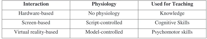
Alternative teaching methods in healthcare have been around for many years, for example medical simulators have been around since the early sixties (Cumin & Merry 2007) and have been used in areas such as anaesthesia, midwifery, dentistry and surgery (Traynor et al. 2010). According to Cumin and Merry (2007) a simulator is described as being based on three attributes: how the user interacts, its simulated physiology and its use. All these factors contribute toward an overall learning outcome from using the simulator which, based on the accuracy and quality of the simulator, will vary. The majority of learning in the field of nursing is said to be gained through practical experiences backed up by underpinning knowledge in the classroom, so it is clear that practical skills are essential for students to be successful in their chosen career (Traynor et al. 2010).
8
Simulators are used for many reasons in teaching and training as they offer many benefits but were first introduced to reduce the risk of patient deaths due to nurses being under-educated in certain areas or simply lacking adequate exposure to practical activities (Bowtell et al. 2012). Some of the benefits of using a simulator are that the user can repeat the experiment over and over again (Bowtell et al. 2012) and do so without any risk to patients (Traynor et al. 2010). Practical skills can be learnt by increased exposure to practical elements of simulator experiments and important lessons learned by learning from mistakes.
'
A
F
F $ C
In order for this type of learning to be effective, the system being used to educate must contain a high level of realism. Guimond (n.d.) describes a nursing simulator in a learning environment as being ‘an experiment that imitates the real environment, requiring individuals to demonstrate the procedural techniques, decision making and critical thinking needed to provide safe and competent patient care’. The realism of a simulator is very important for the student to be able to relate it to a real scenario and therefore enhance their knowledge retention which can be carried over to a real setting. In addition to these points a realistic simulation will not only enhance knowledge but facilitate skill acquisition, decrease any anxiety that could be present in a real scenario and most importantly improve clinical judgement (Traynor et al. 2010).
9
D
BC E F
.
(F /
Research has shown that if students take part in an activity which involves synchronous communication i.e. feedback from the activity is given immediately or immediately after completion, then the feedback received can be absorbed immediately into their understanding and hence built upon. If the activity is still very much fresh in their minds, the feedback whether positive or negative, can be much clearly linked and bound to the completed activity (Finkelstein 2006).
Typical classroom experiences involve completing tasks which must be handed in for evaluation and depending on the size of the class in question, the feedback from the task could take several days or even weeks to be received. The lag between carrying out a task and receiving feedback doesn’t necessarily hinder the level at which learning occurs but prompt feedback has been proven to maintain the students interest and keep them engaged. This ‘promptness’ is especially important in an online learning environment where traditional verbal cues and directions from lecturers are absent (Finkelstein 2006).
Based on the previous paragraphs it is clear that any feedback given in the emulator should not only be prompt but provide enough information for the student to clearly understand what they did wrong (or right). They should be able to associate the given feedback with the recently completed task and apply what they have learnt to the next task, and as we know from experience, people often learn most effectively from their mistakes.
10
)
F
F
D
&
Ryan (2004) discusses in his paper: Role of Faculty in Distance Learning and Changing Pedagogies, that nursing education needs to be brought up to date with technology as times change and that new technology should be used and adopted as it evolves. Web based material is becoming ever more popular in teaching and students’ approach to learning and research revolves heavily around computers and the internet (Lindsay & Good 2003). In faculties such as engineering and science, RAL based learning is very common as well as computer-based environments and web based tools (Aydogmus 2009).
This project follows on from the work and research of Bowtell et al. (2012) in which they describe a remote laboratory as ‘an event that creates a learning experience via remote interface to connect the students’ understanding of relevant information, concepts or ideas (propositions)’. The authors discuss how the advancements of engineering remote/distance learning methods can be used in other faculties such as nursing to improve clinical reasoning skills. They also highlight how literature on remote access is generally focussed on robotic technology and not teaching solutions.
11
,
A
E
$
B F
The author of this project seeks to build on the developed prototype model of an IV infusion pump training emulator as described by Bowtell et al. (2012). The prototype is aimed at confirming that the basic functions of an IV infusion pump (commonplace piece of hardware used in nursing) can be successfully mimicked using typical engineering automation components and controlled remotely by students. Some of the issues in teaching students how to operate the IV infusion pump involved getting them to understand alarms and faults which could not normally be replicated remotely (Bowtell et al. 2012). The feedback from the prototype evaluation was positive but highlighted areas that needed to be addressed in order for it to be a worthwhile exercise for the students. The emulator was initially developed for students to learn only how the IV infusion pump operates however the criticisms from students stressed the need for clinical situations to be incorporated into the activity (Bowtell et al. 2012).
The emulator needs to address several factors to maintain its quality as an online learning tool including its user-friendliness, structure of tasks and navigation (Kist & Wandel 2011). The navigation of the pump menu system will be identical to that of the original but limit certain functionality to maintain focus on the relevant functions for the tasks given. Again a sense of realism will prove invaluable for the emulator to retain its purpose by emphasizing the use of audio and video (telepresence) to keep focus on the experiment and not the system that supports it (Aktan et al. 1996).
12
Table 2.1 - Attributes of Simulators
Interaction Physiology Used for Teaching
Hardware-based No physiology Knowledge
Screen-based Script-controlled Cognitive Skills
Virtual reality-based Model-controlled Psychomotor skills
According to this proposed classification the emulator to be developed will actually fall into two categories. The emulator attempts to be an exact software replica of a piece of hardware functioning identically in every way to the real pump driver yet it still remains a screen-based simulator. Using this analogy it is reasonable to assume that the emulator could be ascertained to teach knowledge and cognitive skills if the balance of realism and task
structure is maintained.
0
FC E + BBFE&
The research conducted points to a niche opportunity for remote access learning tools in nursing and perhaps other academic faculties. There is a lot of material that focusses on simulators/emulators, distance learning, RAL and automation technology but none that offer a solution to tie them all together, especially in the form of a hardware emulator. A small amount of literature has also been found to suggest that SCADA packages are used as educational tools in non-technical environments. For instance a weblab at the University of Cambridge was developed for process simulation using SIMATIC PCS7 software which was concluded to be a successful training tool (Zubia & Alves 2011).
13
14
A $
CDCECF
C
%
D
F
CCE
&
EC
'
F
AB!D
DE FB
This chapter covers the methodology used to develop an IV pump training emulator and the approach that was used to obtain a successful learning platform. This chapter also contains information on the consequential effects of the project and a risk analysis.
'
E
B
B
15
can be successfully designed and tested on their own merit, minimizing possible bugs and errors later in the design process.
By following the design and test procedure for each aspect of every objective, the functionality and realism of the emulator can be maintained.
'
*
D
BF
B
D
AE
E
&
EAD
Firstly the task to be completed should be determined. This could be something simple like creating a button that when pressed allows a graphic to become visible on the current HMI screen. It is essential to try and minimise the task and not be tempted to add extra tasks into the procedure that might allow the potential for errors to be incorporated even if the tasks are closely related.
& ' C
!
Depending on the type of task in question, each idea will differ. However it is a good idea to take a step back and think about the best way to program a solution to the problem. This simple step may highlight a reason as to why that programming idea wouldn’t work. By taking time to consider each possible solution, failed attempts can be avoided which will result in time saved and less redundant code.
( C
BB
C A
CD C
)(
*
16
+
A
C A
The ladder logic can now be written with the predefined tags. A visual check of the ladder logic should be done to check for any possible errors which can be rectified at this stage.
&C D C
C (
Once the coded sequence seems sufficient, the program can be downloaded to the PLC to ensure that it is up-to-date and ready to be tested.
,$!
Due to the current version of software that is being used, the tag list in the PLC cannot be integrated into the HMI software. Therefore each new tag has to be re-entered into the HMI tag list. The tag name should be the same as the tag name given in the PLC to be consistent and avoid confusion. Other parameters such as data type and address should also be checked.
A
The required graphics can now be drawn, created or imported as necessary. If a button is created, the correct tags need to be associated with it ensuring the bits are set and reset as required.
AD - .A A A A
17
/
' 0 C
1 D AB
-Once finished the changes should be saved and then the run-time can be started. The newly incorporated features can now be tested to ensure that they perform as required and fulfil the requirements of the task discussed in Define Task. All possible scenarios should be exhausted to ensure correct functionality.
$
2
D
If any problems are detected then these should be remedied before moving on. If changes to the logic need to be made then the procedure should be repeated from the beginning to make sure all changes ripple through to the final design.
1
A
A final reality check should be undertaken to verify that the added feature is consistent with the flow of the emulator and maintains the realism required for this project. The software can now be saved and the next task commenced.
' '
DF /
B$
F
&
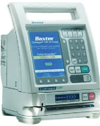
18
Figure 3.1 - IV Infusion Pump Driver
' '
* "
C
F
%1
B F
F
A BC *E " E
For an emulator to truly reflect the system it is emulating, a sense of reality must be present in every aspect of its functionality. The actions and reactions of the emulator must mimic the driver exactly and make the user believe it is functioning as the real system does. In order to achieve a sense of reality for the pump driver emulator, several elements and tools will be used in the process. These elements are described in the following paragraphs.
In order to understand the functionality of the driver, the documentation provides essential information on how the driver operates and offers instructional help in navigating the menu systems. The documentation provides everything from user guides to technical details and it also provides graphics and symbols in its explanations. These graphics can be used to help develop the HMI platform.
19
By providing exact (or at least close to exact) replicas of the pump driver screens and graphics, the user becomes familiar with the look and orientation of the graphics and screens. The user must be able to interact with the graphics interface of the emulator, understand it and then reproduce their actions on the pump driver. All graphics encountered using the emulator must be a direct reflection of what the user is faced with when operating the IV pump driver.
To add another level of realism it is important to include any sounds that the driver produces. The sounds of the pump driver are actually of great importance as the alarms and safety features rely on loud piercing beeps that get the users attention in the event of a fault or procedural error. Nurses must be able to recognise these alarms and react in the correct and responsible manner to remedy the problem causing it. By becoming familiar with the sounds of the emulator, they will be well prepared for dealing with real issues and alarms when exposed to the pump driver in an occupational environment.
Mimicking the sounds could prove to be ineffective if using standard beeps etc. that have been downloaded from an audio database. In order to retain the maximum amount of realism, the driver will be operated and the sounds recorded for every possible outcome. The audio files can then be called upon by the programme at relevant points in the sequence. The emulator must mimic any push button sounds, alarms or even pump noises, this is done by careful observation and monitoring of the pump drivers operation and recording the response to certain user input.
20
' '
EF
%1
B F
#
E
Developing the HMI platform is just part of the solution for the successful completion of a functioning system emulator. In order for the interface to operate as required, it must be controlled by some sort of logic.
A program must be written to process the user inputs to the system and control any sequences within the emulator. The programme must run in the background and allow the precise control of all I/O to the system.
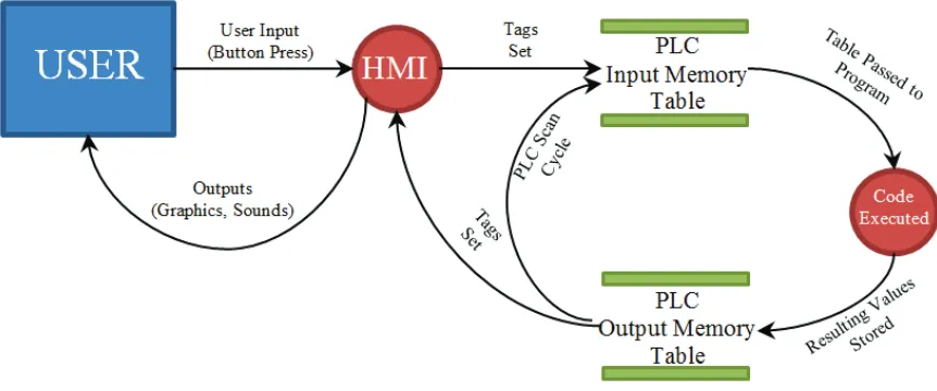
The HMI simply passes information to the programmable logic controller (PLC) based on the events that have taken place. Each event will be associated with a tag (or tags) that relay the information to the PLC in different ways depending on the tag type. Typically, the majority of tags will be of a digital nature simply representing an on or off state for each event. However there will be a requirement for analogue values which will be related to objects such as the numeric keypad and numeric displays of values on the screen.
Information sent from the HMI to the PLC varies depending on the conditions of the inputs. A snapshot of these input conditions is saved in an input memory table and the control logic processed sequentially. The resulting values are saved in an output memory table and then passed to the outputs, which are in turn processed in the HMI.
[image:35.595.115.546.558.738.2]The data flow diagram in Figure 3.2 represents this process graphically.
21
As it can be seen in Figure 3.2 the PLC performs a continuous scan, (constantly updating the conditions of the I/O) and processes them through the control logic to produce a new set of outputs. This is done regardless of any changes to the inputs themselves. The scan time depends on the size of the program that has been written but is generally a minimum of around 10ms. There is obviously a resultant lag time that occurs between a button-push and a change on the HMI screen, this also depends on the HMI refresh rate (time interval between screen updates). The HMI refresh rate can be configured to update in milliseconds.
' ' '
* "
C
"F
.
*E " E
E
F
- FE
2F /
E
As a minimum for the emulator, it should be able to mimic the relevant functions of the pump that the nurses would be required to operate. These functions are described in the following paragraphs.
Every time the IV pump driver is energised it automatically runs through a start-up sequence, so it is important to incorporate this into the emulator. During this sequence the pump runs through its self-diagnostics test (SDT) in which the screen, pump display and light emitting diodes (LED’s) cycle through a test sequence. It also requires the user to perform a speaker check as the speaker is very important to ensure that the alarms can be heard, as discussed in section 4.4.5. The start-up mode also allows the user to select New Patient, which clears the previous patients’ data comprising of the rate and volume to be infused (VTBI) values.
In addition to the start-up sequence, the main function required to be emulated is the infusion mode. This is where the user must enter an infusion rate and a VTBI using the keypad. Before the infusion can be started, a virtual tube must be inserted into the pump using the correct procedure, a virtual clamp released and a final check of the 6 rights performed (see 5.3).
Some basic alarms must also be developed including:
22
Tube not Inserted (The user has attempted to start infusion but the tube has not yet been inserted into the pump module)
Downstream Occlusion (The user has attempted to start infusion but the cannula clamp has not yet been released which is located between the pump and the patient)
Unconfirmed Primary Program (The user has attempted to start the infusion before pressing the ‘confirm primary’ button)
ABCDE A BFE
B
AB
AB
The control system that will be used for this project is a SIEMENS S1200 PLC, which requires a software package called SIEMENS TIA Portal v10.5.
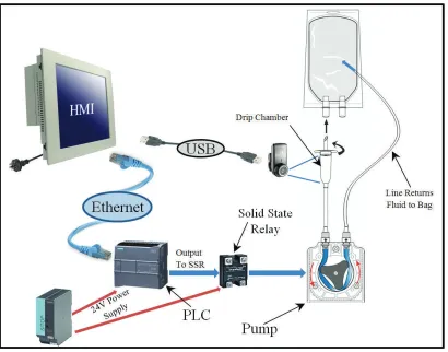
In order to emulate the function of the pump module, some additional hardware components must be connected to the PLC. To emulate the concept accurately, a nursing administration set (bag, drip chamber and tubing) will be required to be set up and connected to a suitable peristaltic pump.
23
Figure 3.3 - Peristaltic Pump in Use
Figure 3.4 - Diagram of Peristaltic Pump Operation
[image:38.595.204.429.405.598.2]24
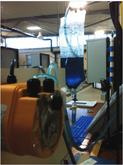
The hardware will be mounted on a display board and the instruction set is set-up next to it. A webcam will also be connected to the personal computer (PC) to allow the user to experience something happening in the ‘real world’ and not just within the software. The webcam shows a view of the drip chamber to display the drip rate associated with varying flow rates and to indicate that the pump is running.
[image:39.595.115.525.261.583.2]The hardware setup is illustrated in Figure 3.5.
25
' ' )
$
B
1
EF
F
F
+
&
EC EF
In learning mode the user will learn how to use the pump driver with the aid of a walkthrough which guides the user through every necessary button-push. Assessment mode not only tests the level of competency in operating the IV infusion pump driver, but also incorporates real life case studies to further enhance the activity. The case studies are prepared by the faculty of nursing and are similar to case studies that are used for the real pump.
By incorporating regular case studies into the assessment, the user is encouraged to focus their attention on the problem at hand and not on the ‘novelty factor’ surrounding new computer emulation. The realism of the pump driver emulation will also help achieve this and convince the user that they are performing a regular case study on a regular piece of equipment. It is intended that the user incorporates an actual fluids chart into the whole process.
The case studies will present the user with several different realistic scenarios which will describe a patient’s vital statistics, diagnosis and medication order. Based on the given information the user must be able to calculate the correct rate of infusion and VTBI in addition to setting up the pump correctly.
' ' ,
"F F
B F
E
F
B F
F &
E
+ E" &
Once the emulator has been developed and each aspect tested to ensure functionality, it needs to be presented to the faculty of nursing to undergo evaluation through trials.
26
realistically. Feedback from the users themselves will highlight any interface issues for non-technical users and also indicate whether they felt the emulator gave them adequate familiarisation with an IV pump driver.
' ' 0
"F F
B F
E - FE
!
B
E
+ E" &
The feedback from the faculty of nursing will highlight any problems or errors that could aid in the optimisation and further development of the learning environment. Consistent communication with the faculty of nursing will ensure that the emulator evolves into a technically sound and optimised enhanced learning activity.
The emulator is designed to eventually be accessed remotely via the RAL system, but initial evaluation, testing and feedback may be performed OC using the remote desktop Protocol (RDP) system. Once this phase is complete, a pilot level study will utilise the RAL system to avoid booking and off-campus connectivity issues.
' ' 4
"
F
B F
A BC *E " E 3
+
#FE
! &
The use of additional hardware as detailed in section 3.4 may not be entirely necessary in order to achieve the same level of learning outcomes. This objective seeks to determine whether the users obtain an adequate understanding of the exercise without having the opportunity to view the drip chamber via a webcam.
27
entirely in a software package. If this is a viable option, the project could be emulated 100% in software, reducing the cost and hardware complexity of the project.
' ' 5
* "
C
E
AF
E $
F
F
F
A BC
EBF
To successfully navigate the menu functions of the pump emulator and complete the assessment mode, the user need only become familiar with the learning mode activity. However in addition to the learning mode section of the emulator, an additional resource page will be developed. This resource page will contain some important information for general infusion procedures and also some information on the pump itself. The page may also contain video tutorials or whatever the faculty of nursing deems necessary or appropriate for this activity.
The information provided on the resource page aims to impart some knowledge of the important features of the pump that the user may come across in a real occupational situation. It is also there to support complex procedures that are difficult to demonstrate within the emulation itself, such as tube loading.
' ' 6
*F F F
E
F
$
B
3
E A E EBF
Upon going through the information resources provided and attempting the learning mode of the emulator, the user must complete the same task in the assessment mode. In this mode, there will be no pop-ups or hints on how to complete the infusion set-up. The user must successfully navigate the menu system and complete a series of case studies based on pre-determined circumstances and values.
28
performance assessment provided at the end of each case study will display whether a particular part of the procedure was completed correctly or not along with a short description.
' '
* "
C EE E DE
AF
In addition to the feedback page a link to a trend page will be provided. Each case study will have its own error trend page which will be capable of showing each error identified on the regular evaluation page against time.
The number of possible errors in each case study may vary, however a simple visual representation will be developed to show when and in what order each error occurred. This would be another example of how specific features of SCADA software can be utilised in different ways, in this case for assessment feedback.
'
7
F
The possible consequences of introducing this project to the USQ education system have been investigated and areas such as sustainability, safety and ethical dimensions have been addressed. (Research Project Reference Book 2012, p.77).
'
+
F F(
&
29
considerations throughout the life cycle of a project. The hardware used in this project was made from materials which contribute to energy consumption during the manufacturing processes, issues relating to manufacturing processes are beyond the scope of this project. The devices consume energy whilst in the development stages of the project however the equipment will always be de-energised when not in use. Upon completion, the emulator will be running 24 hours a day, however if the project concludes that additional hardware it not essential, then costs, energy consumption and skills requirements can be reduced.
'
+F
&
The system will consist of a panel PC, a PLC and power supply, a pump and termination materials. All of these items must meet the required Australian safety standards and all electrical connections to be connected by a qualified electrician as outlined in AS/NZ 3000 (Australian/New Zealand Wiring Rules).
' '
F * B
In relation to engineering practices EA’s Code of Ethics: 2000 outlines the expectations of the engineer to perform his duties with integrity, competence, leadership and sustainability. The code of ethics will act as a guidebook to all decisions that need to be made throughout the life of the project. The best interests of the community will be kept at the forefront of all matters.
For this project is imperative that the assessment of user performance is defined clearly and fairly.
30
' )
D
/
B$ F
&
For any project the safety issues need to be identified and addressed accordingly to comply with such legislation as the Workplace Health and Safety Act 1995. This act has one major objective which it seeks to enforce through various methods:
“The objective of this Act is to prevent a person’s death, injury or illness being caused by a workplace, by a relevant workplace area, by work activities, or by plant or substances for use at a relevant place.”
Initially, this project doesn’t appear to have many risks associated with it. However a more detailed analysis reveals some potential hazards and the risks thereof that can be brought to attention through a proper risk analysis procedure.
A hazard is the level of threat to people, property or the environment that has the potential to cause harm. Whereas the risk associated with a hazard is the likelihood of the hazard to actually cause harm. The relationship between a hazard and its risk can be identified through a risk analysis, described in the Australian standard:Risk analysis of technological systems
as ‘the systematic use of available information to identify hazards and to estimate the risk to individuals or populations, property or the environment.’
This type of analysis is quantitative and can provide the user with an indication of the severity of each risk.
' )
/
F
8* E
9
AE
:
31
%
A A
• All electrical appliances or devices that operate on mains power must be tagged and
tested to prove they are fit for use.
• Appropriate fuses must be selected for the control equipment to avoid damage and fire in case of a fault.
• A qualified electrician is to wire up the 240V power supply to the PLC and Pump.
• Food or drink will not be consumed around electrical apparatus.
• Backups of project files to be made on regular basis in case of PC failure.
A
AD
• Poorly lit areas can cause headaches and/or eye strain, ensure lighting is adequate
and monitor well positioned.
• Use screen filter where necessary.
/
• Working on the project for long periods of time may become stressful. • Operator to divide up work into manageable sections.
• Healthy diet, exercise and regular breaks will reduce the chances of stress.
2CA
• Noise from appliances such as pumps can be harmful to hearing over long periods of
time.
• Damaged equipment may also increase noise levels.
32
$
D
, D
AD
• Some pieces of equipment can be heavy and cause injuries if manual handling
techniques are poor.
• Seek assistance from others where required.
' ,
D
/
B
"F F
The above risks can be evaluated in a risk matrix similar to that shown in Figure 3.6.
Figure 3.6 - Risk Matrix
Key:
33
Using the matrix shown in Figure 3.6 each hazard can be evaluated and a quantitative rating given (See Table 3.1).
Table 3.1 - Risk Evaluation Table
Hazard Likelihood Consequence Rating
Electricity 2 5 10
Lighting 4 1 4
Stress 4 3 12
Noise 2 2 4
Manual Handling 3 4 12
' ,
D
/
B
E
F
+ BBFE&
As it can be seen from the results in Table 3.1, the project contains only low to medium risks which will be trivial if a safe and responsible behaviour is maintained throughout the life of the project.
It is important to be aware of any risks that may be present in a given project and to act appropriately to minimise the consequences of those risks where practicable.
' ,
/ ; &
BC
AE
34
' 0
A
E
D B
Throughout the life of any project it is imperative that an overview of project tasks and methods on how to accomplish those tasks is produced, monitored and maintained. However these aspects of project management need to be brought into context and projected across a realistic timeframe for the given project.
By producing a Gantt chart, all the individual tasks of the project can be viewed in sections and their estimated time requirements presented. This allows an easy comparison of the current progress with where the project should be, or was estimated to be.
The chart used throughout the project is shown in Appendix B. The project was finalised in mid-August showing that it was completed ahead of schedule.
' 4
AE
E
7 E B
35 Table 3.2 - Resource Table
Resource Quantity Cost Per Unit
($)
Cost
(Hours)
IV Infusion Pump 1 0.00
-Instruction Set 1 0.00
-Computer/touch screen 1 1750.00
-PLC 1 920.00
-Power Supply 1 240.00
-Fuses 2 18.00
-Terminal strips 2 24.00
-Ethernet cable 1 47.00
-Wiring (m) 1 0.00
-Device board 1 0.00
-Pump 1 300.00
-Webcam 1 0.00
-PLC software 1 570.00
-HMI software 1 1750.00
-Windows OS XP 1 0.00
-USQ Staff 1 - 68
USQ laboratory and access rights 1 - 128
36
' 4
E
Table 3.2 shows a list of required resources for this project. Any costs displayed as being zero dollars indicates that it was free or that the resource was already available at USQ. The power supply, wiring and termination equipment were obtained from the faculty of engineering’s technical laboratory including the Ethernet cable.
An instruction set and pump driver were provided by the faculty of nursing and midwifery. SIEMENS hardware was chosen for this project as the university had secured a good package of SIEMENS control equipment for educational purposes.
The costs shown are unit costs only and were purchased by the Learning Teaching and Performance Fund (LTPF) for use in future RAL projects including several PLC’s and Panel PC’s. The equipment was therefore already available which means that there are no costs associated specifically to this individual project.
' 5
FC E + BBFE&
This chapter explores the methodology that will be adopted throughout the duration of the project and in particular describes each step the design and test procedure which, if applied correctly and consistently, will ensure that the project flows smoothly from one task to the next.
37
A
B
CD
EF
F
C
D
F
F
AB!D ADE FB
In order to ensure that the project progresses smoothly and successfully, some planning needs to be considered concerning the flow and methodology described in chapter 3.
38
%F
E #FE
B
The hardware used in this project should enhance the learning experience by providing a real pump to circulate the fluid and a webcam to give some visual feedback to the user. Therefore the hardware needs to be setup correctly from the start and tested. Once this phase is complete and setup, the software can be implemented over the top and development can begin.
* "D
B;
FE
Figure 4.1 - Control System on Device Board
39
[image:54.595.220.416.118.381.2]The instruction set will be mounted on a stand near to the pump and the liquid will contain a blue dye to make it easier to see, as shown inFigure 4.2.
Figure 4.2 - Pump and Instruction Set
%F
E #FE
B
BB
F
The hardware needs to have an established communication link in order for the HMI screens to be able to transfer data to and from the PLC. This isn’t as straight forward as just connecting an Ethernet cable, there are a few things that need to be done.
The default IP address of the PLC is 198.168.0.1 (subnet: 255.255.255.0), therefore the IP address of the relevant network card in the PC needs to be in the same IP range. The PLC can be assigned a new IP address by reconfiguring the properties of the PLC. This is done by using the software package SIEMENS TIA Portal. Although it is simpler to just change the IP address of the PC to 198.168.0.2 (subnet: 255.255.255.0) for example.
40
[image:55.595.148.491.569.738.2]prompt the IP addresses of all the network cards connected to the PC will be displayed, this verifies that the PC end has been correctly configured (SeeFigure 4.3).
Figure 4.3 - Screen Shot of IP-Config Test
It can be seen the network card of interest is the Ethernet Adapter Local Area Connection 2. Ethernet Adapter Local Area Connection 1 is connected to the USQ network.
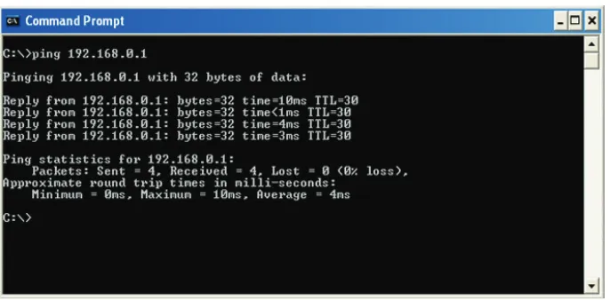
Secondly, by typing ping 192.168.0.1 a simple handshake test and the corresponding round-trip time will be displayed if the connection to the PLC is successful (See Figure 4.4).
41
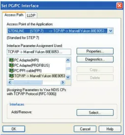
[image:56.595.192.446.251.524.2]Finally, before the TIA software can connect to the PLC to download a program there is a setting in Windows control panel called PG/PC interface (that is added after installing SIEMENS software) that needs to be set (See Figure 4.5). This sets the interface for the specific SIEMENS software that is in use and establishes what kind of connection is to be used. In this case Ethernet using transmission control protocol / internet protocol (TCP/IP) was used for the STEP 7 range of software.
42
'
A- B+
#FE
43
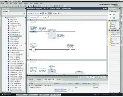
Figure 4.6 - Screen Shot of TIA Software - Typical View
'
;
/ <
# E/ F
DF
The purple and blue objects in the left hand pane of Figure 4.6 are blocks. There are different types of blocks that can be used in the software to perform different tasks, for example there are start-up blocks that are only executed once on start-up, data blocks that allow tags to be defined or parameters set or organisational blocks in which code can be written and organised. Counters and timers automatically produce a corresponding data block.
44
logic, which aids in fault-finding/debugging. Within each block the logic can be further organised into networks, this can be seen in the right hand pane of Figure 4.6.
As mentioned above, tags are defined in data blocks. It is good practice to create a corresponding data block for each organisation block as these tags can be well organised. Within the data blocks the data type, address (memory location) and name can be defined. If changes to a tag are made here, the changes will be rippled through every part in the program where that tag is used. The naming of the tags is also very important to keep things organised. The naming convention of tags in the logic will be defined by the appropriate HMI sequence, followed by its function.
'
+ 7
B
As there are a lot of features to capture in the HMI, it is essential for the logic to be able to cope with the vast number of events that will be happening. A technique that will be adopted in order to accomplish this task will be to use numbered sequences for the execution of a series of events. A series of events or timers will trigger the corresponding sequence number to be moved into a memory location. Each sequence number will be compared to the number in the memory location (called the sequence step) and the current sequence will be enabled (See section of logic in Figure 4.6). The next sequence step can only be enabled if the previous sequence step is currently enabled.
Whilst the HMI is in a specific sequence, events, objects, sounds and alarms etc. can be associated with that sequence. Obviously these items can be associated with multiple sequence steps if required. This allows a more sophisticated level of control and also aids in debugging.
' '
1
E
F
D
45
time allows the user to see which parts of the ladder rungs are energised and also to see current analogue values. This is a useful tool for testing sections of code, for example an input or memory location could be manually toggled and the control logic monitored to visually prove that the logic is functioning correctly.
A watch table is simply a list of tags that the user has selected to view. The values of the tags can be dynamically monitored and forced to change their state or value. This is also useful for testing.
Possibly the most useful tool in the software is the cross-reference function. By clicking on any item in the ladder logic, the properties window at the bottom of the screen can display the cross-reference section which will show everywhere where that particular item is used. This includes the block name and network number and whether it is being written-to or read-from. The added advantage is that each reference can be clicked on and then the section of code where the item is used will open up and be displayed (See Figure 4.6).
A full listing of the control logic can be found in Appendix D - Control Logic Listing
%1 B+
#FE
The HMI software used for this project will be SIEMENS WinCC Flexible 2008. The software has many attributes that allow the importing, creation and editing of graphics and objects etc. The objects on a page have properties that can be configured to fulfil the requirements that the HMI program requires.
46
Figure 4.7 - Screen Shot of WinCC Flexible 2008 - Typical View
AF
B
The pages (or screens) in an HMI system can be configured to display different parts of a process or alarm or configuration pages. The screens can be easily navigated to by linking buttons or events to switch to another page. The PLC logic was organised into blocks to ‘spread the load’ and define manageable sections, similarly the HMI sequences were also spread over several screens to achieve a similar outcome.
47
unnoticeable. This method proves to be effective and if more menu functions or sequences are required, additional pages can simply be added.
-F&
E
D
B
F
B
E
C
In addition to spreading the load across multiple pages, the graphics can be further organised on each page by assigning them a layer. The layering functions similar to the send backward and send forward layering in common graphics software packages except a layer number can be chosen from 0 to 31 (32 layers in total) 0 being the lowest and 31 the highest. This function is particularly useful for editing graphics that may lie underneath something else, as all other layers can be hidden whilst editing is done on one particular layer at a time. Again, similar to other graphics software packages, objects can be grouped together to form a single object. For example some shapes, text boxes and buttons can be grouped together to form a pop-up box similar to the pop-up shown in Figure 4.7.
'
DF
48
D D(D
& F
"
The tags described above will be used within the HMI pages to enable control of the graphical sequences etc. Each object on the screen comes with object-specific properties that can be configured by the user to perform certain tasks. As an example; a button on the screen could be made to be invisible until tag A is set, will set tag B when pressed and reset tag C when released. All the possibilities for triggering events and animations are vast and will not be listed here. However events can be controlled by the PLC, the HMI or a combination of both. For this project, all control functions (as many as practicable) will be performed in the PLC as it is easier to perform fault-finding in the PLC software.
)
$ FEB
In industrial applications alarms play an important role in any SCADA system. They are generally triggered by events that are considered warnings, errors, faults or problems. They make the user aware that something is not quite right or needs attention. The pump driver itself has built in alarms and the HMI can be set up to mimic these alarms. The HMI has the advantage of being able to display and/or log activated and deactivated alarms and whether they were acknowledged or not. Although the emulator will function quite differently from an industrial process, the alarm feature may prove invaluable when conceiving methods in which to assess the users’ performance.
)
D
<
BB
F
F
.
(F /
49
gauge the ‘user-friendliness’ of the emulator for nursing students and to give constructive feedback on how the emulator will be used to display information and assess the users etc.
)
1
FE D
As the development of an IV pump driver emulator is a huge task, it needs to be broken-down into manageable sections. Firstly the main sequences will be identified and then each sequence broken-down into every graphical change or transmission. To ensure each transition works correctly and flows seamlessly into the next one, they will be individually developed and tested before moving on. For example if a button needs to be created that enables another sequence to become active, the development and placement of the button needs to be checked and tested to ensure that it works and any events associated with the following sequence occur as planned. The PLC logic will be written along-side the HMI development to keep track of each section. When the outcome is satisfactory it can be considered functional and the development moves on.
By following this method throughout the life of the project, no logic or HMI components will be missed or deficient.
)
%FE #FE D
The hardware that needs to be tested is the pump and the webcam. The webcam is simply a plug and play USB (Universal Serial Bus) device that requires some software to be installed for it, the drivers are automatically installed through the Windows OS.
50
to be enabled and the cycle time determined. The time-base can be set to microseconds or milliseconds and the pulse width set to a resolution of 100 or 1000.
The Pump was tested with the settings configured to microseconds and a pulse resolution of 1000. The pump seemed to run at full speed regardless of the value entered for the pulse. The same was then undertaken using a time-base of milliseconds and the pump responded to the changes in pulse width, albeit with a slightly jerky action. It was concluded that the interposing (solid-state) relay could not switch quick enough to regulate the speed of the pump and just saw a constant high state. However for the purposes of the emulator this was still acceptable.
,
FC
E + BBFE&
This chapter has explained what is required in order to set up the necessary resources of the project and link the hardware and software through communications settings and testing. Setting up the device board and developing basic software for it to function with is required as a platform on which to design and build the rest of the emulator functions on.
51
A BCD EF C
)
F
AB!D ADE FB
This chapter investigates the emulator features in more detail. In particular the general look and feel of the emulator will be discussed and methods as to how practical elements of the activity were achieved.
Each sectio