Abstract: Most of the chemical industries are used with Polyurethane (PU) coated steel sample which is found that some chemical reaction and rusted in acidic bath solution becomes a problem in industry. For such problems composite materials can be of good solution which does not possess any reaction with working fluids (acids in our case). With composites there is complexity of manufacturing and high cost involvement, so as to avoid those simplified approach is used to get Flat plates made of Glass fiber reinforced in epoxy which is best solution for any acidic bath as it possesses high resistance to any reaction with itself. Glass fiber plates are cut into the size of dimension and with the help of adhesives joint the WFJ of I-Beam, there are two different types of adhesives used, araldite 2015 and Hundsman araldite are used. The hundsman araldite is found to get better performance of Web-Flange junction (WFJ) joint. Finite element analysis (FEA) is used to get initial validation and further it’s observed that Hundsman araldite failure strength on the web-flange junction is better. Also, additional cleat used with 4 mm, 12 mm for increasing the Web-Flange junction (WFJ) area to improve the Load carrying capacity of the Beam. The experimental analysis results clearly indicate that the emersion of the reinforced epoxy glass-fiber in the acidic bath solution for a certain period, there is no any reaction formed in the acidic bath and improved the behavior of the specimen. Results from FEA and experimental test have shown good correlations are obtained with improvement of failure strength on WFJ.
Keywords:FEA, Epoxy glass fiber composite material, tensile load, ANSYS.
I. INTRODUCTION
Rolled Steel Joist, Universal Beam, H-beam, is also known as I-beam with an H or I shape cross section. The I-beam is made by two different section horizontal element is called as flange and the vertical element is called as web. The flanges counterattacks mostly in the bending moment and the web counterattacks shear forces practiced by the beam. The Beam theories are very efficient in the form of both shear force and bending moment in I-shaped segment with the plane of the web. Alternatively, the cross-section has an inefficient in carrying torsion and reduced capacity in the transverse direction, for which mostly have considered the hollow structural sections for improving the failure strength. I-beam is made up of two different processes 1. Plate girder, made by welding plates. 2. Rolled I-beam, made by extrusion, cold rolling, hot rolling. The I-baem is mostly used in
Revised Manuscript Received on November 05, 2019.
Mahesh B. Mane,Design Engineering, Dr. D Y Patil School of engineering, Pune, India. Email: [email protected]
Dr. F B Sayyad, Mechanical Engineering, Dr. D Y Patil School of engineering, Pune, India. Email: [email protected]
Dr. Mohd Imran Ansari, Mechanical Engineering, Dr. D Y Patil School of engineering, Pune, India. Email: [email protected]
[image:1.595.311.540.279.628.2]automobile, chemical, mechcanical industry and construction work in civil engineering work . We select I-beam which is used in chemical foctory for stirrer mounting mechanism. Fig.1 shows that the geometry of I-beam is taken from ISMB 80 standard for using the sample of stirrer mounting mechanism. Height of the I-beam is 80 mm, flange width 50 mm and Web and Flange thickness 5 mm.
Fig. 1. Geometry of I Beam model
The I-Beam is mostly used in industry, construction work, aircraft, automobile industry, chemical industry etc. I-Beam we can chose which is used in chemical industry for stirrer mounting mechanism. This I-beam is made up of steel with PU coating Web-flange junction of that beam is joining by welding or nut bolt joint. This I beam is completely deeded into the acid and the acid is benzoinic acid some after time the coating of PU is rusted, and this acid is reacting with the steel. This reacted we cannot use anywhere or cannot be destroy it for that problem we can replace I-Beam with composite beam which is made of epoxy glass
fiber material. But the most of failure of I- beam is Web Flange
Design of Composite I-Beam Section to Prevent
Web-Flange Junction Failure and Improving Its
Axial Load Carrying Capacity
junction (WFJ) this problem is reduced by using adhesive. There are two type adhesives used 1st is Araldite 2015 & 2nd is Hundsman araldite & find out which is better for the application. The starrier & motor are mounted on that beam and starrier rotate 5-6 rpm continuously, but some time beam is failing at WFJ and total structure is deeper into the acid solution. There is less area of joining that’s why we can use the extra cleats of 4mm and 16mm as per your application required.
II. METHODOLOGY
The main object of this project work is to find find out the structural I beam by using reinforced epoxy glass fiber composite materials to avoid the problem of chemical reaction with steel and to avoid the WFJ failure by using the adhesive. The mathematical calculations are carried out by using the emperical formulae.
Finite element model is built in ANSYS workbench. Fine mesh with higher order element is generated to achieve the mesh convergence. Geometric ,contact and material is defined the FE model. Epoxy glass fiber composite material model is used in ANSYS workbench.
III. PROBLEMSTATEMENT
This I beam is completely deeped into the acid and the acid is benzoinic acid some after time the coating of PU is rusted, and this acid is reacting with the steel.
In I beam structure web resists shear forces while the flanges resist most of the bending moment experienced by the beam. Most of times failure occurs at joining section of web and flange. So, the complete bonding between these two is very essential part.
So aim of this paper is to find out the structural I beam by using reinforced epoxy glass fiber composite materials to avoid the problem of chemical reaction with steel. To calculate the stress and force of composite I beam at web-flange junction using FE analysis. To improve the failure strength of I beam which is used to adhesive at WFJ.
IV. NUMERICALFORMULATION
The type of the composite I-beam in simply supported type.I-beam is taken from ISMB 80 standard for using the sample of stirrer mounting mechanism. Height of the I-beam is 80 mm, flange width 50 mm and Web and Flange thickness 5 mm. This dimensions are used for calculating the area and calculating the stress at WFJ.
Table-1: Dimension of composite I-beam
Beam Type
Height of beam (mm)
Width of flange (mm) Thickness of Web (mm) Flange Thickness (mm)
ISMB 80 80 50 5.0 5.0
As shown in above Table 1 the dimension of composite I-beam. This dimension of I-Beam is selected from the Indian standard medium weight beam chart. This beam is ISMB 80 &this dimension is standard.
1) Area of flange and web= b*d
Where,
b = breadth
d =depth 2) Total area of beam= A1 + A2 + A3
Where,
A1&A3=area of flange A2=area of web
Total area of beam (A) = 850mm^2 3) Moment of inertia (I) = I1 + I2 + I3
I1 = bd^3/12 + A1 (Ymax – Y1)
Where,
Ymax = Distance from bottom to N.A
Y1=distance from flange bottom to flange N.A Moment of inertia (I) = 7.646E6 mm^4
Stress = P / A Where,
P= force
A= Area of beam
V. FINITEELEMENTANALYSIS(FEA) This chapter describes the finite element model of composite I-beam. Then finite element analysis techniques applied in this thesis were explained because in a typical FEA simulation usually 80%-90% time is spent to find the best parameter settings. Finally a three dimensional, contact FEA model was created in ANSYS workbench, and the results were compared to the physical testing results with the same geometry to verify the accuracy of the FEA model.
Material Properties
Table-2: Properties of glass Fiber-Reinforcement Materials
Fiber Property Glass Fibers
Diameter (µm) 8-14
Density (kg/m3) 2560
Modulus of Elasticity (GPa) 76 Tensile strength (GPa) 1.4-2.5 Elongation at fracture (%) 1.8-3.3
As shown in above Table 2 shows that the material properties of material of glass fiber which is used as reinforcement material.
Table-3: Properties of Epoxy matrix Materials
Matrix Property Epoxy
Density (kg/m3) 1100-1400 Modulus of Elasticity (GPa) 03-Jun
Tensile Strength (GPa) 0.035-0.10
Compressive Strength (GPa) 0.1-0.2
Elongation at Fracture (%) 01-Jun
As shown in above Table 3 the material properties of Epoxy and which is used as matrix material for producing the glass fiber epoxy resin material.
FE model information:
It is very much important to model the finite element model with the boundary conditions which are very close to real world conditions.Hence to ahive the high level of accuracy non linear FE analysis has been carried out.Multi-linear stress strain curve, frictional contact
FE model. Non linear analysis is carried by using ANSYS software package. Firstly, finite element analysis has been carried out on current design (baseline model). The fine mesh is used so as to get the most accurate results.
2D Modeling of I-Beam:
[image:3.595.341.504.52.230.2]CAD software like CREO which is used for generate 2D model of the project .We can use CREO for generate the I-beam model and which is converted into IGES formate.Fig 2 shows that the Creo model of the I-beam.
Fig.2.Creo design of I beam Loads and Boundary conditions
This I-beam is used in acid chemical factory for stirrer mounting mechanism in these flanges are connected at the tank & the load bearing is mounted at the web in this one end of beam is fixed and load is applied at another end this load is the tensile. This load is the motor and stirrer weight which is mounted at the I-beam. Load and boundary condition is shown in the Fig.3.
Fig. 3. Loads and Boundary conditions Analysis results of I-beam model:
The conventional model is developed into the CREO software and this model converted into IGES format which is imported into the ANSYS software for the analysis purpose. There are two adhesive used for joining the WFJ 1st one is Araldite 2015 and 2nd one is Hundsman araldite and then find out which better for joining WFJ of composite I-beam.
I-Beam with Araldite 2015 Adhesive:
Fig.4. Von misses stress with Araldite 2015 The above Fig.4 shows the Von Mise stress plot. The max Von mise stress occurred on WFJ is 10.79 MPa and load carrying capacity is 14945 N.
I-Beam with Hundsman Araldite Adhesive
[image:3.595.69.268.173.334.2]Following Fig.5 shows the Von Mise stress plot and max load carring capacity plot. The max Von mise stress occured on WFJ is 10.363 MPa and load carrying capacity is 15269 N.
Fig. 5 Von misses stress with Hundsman araldite
Analysis results of nonlinear model
[image:3.595.323.493.338.487.2]Now in this step, FE model is solved by considering the two different adhesive with composite I-beam. Table.4 shows that the maxi stress concentration at WFJ of the I-beam with Araldite 2015 and Hundsman araldite.
Table-4: Stress concentration at WFJ of I-Beam Sr.No I-Beam with adhesive Stress (MPa)
1 Araldite 2015 10.79
[image:3.595.73.267.450.621.2]Fig.6. Stress concentration of I-beam at WFJ with adhesive
As shown in above Fig.6 the graphical representation of stress concentration of I-beam at WFJ with adhesive.
From above Table 4 and Fig.6 shows that the hundsman araldite is better adhesive material as compare to the araldite 2015 because its stress concentration at WFJ is less and load carrying capacity is more. Stress concentration At WFJ of the Hundsman araldite is 10.36 MPa and Araldite 2015 is 10.79 MPa and force capacity of Hundsman araldite 15269 N and Araldite 2015 is 14945.
In this I-beam structure there is less area of joining at WFJ then the beam is failure at the junction to avoid this problem we can use the extra cleat which dimension is 4mm and 16mm which is available in the market for incresing the area of jioning which is increas the load carrying capacity of the beam.
I-Beam with Hundsman Araldite and 4mm Cleat
Fig.7 Stress of I-beam Hundsman araldite with 4 mm cleat
As shown in above Fig.7 the Von Mise stress plot. The max Von mise stress occured on WFJ is 12.96 MPa and load carring capacity is 17018 N.
I-Beam Hundsman Araldite Adhesive with 12mm Cleat
Fig.8 Stress I-beam Hundsman araldite with 12 mm cleat
As shown in above Fig.8 the Von Mise stress plot. The max Von mise stress occured on WFJ is 13.64 MPa and load carring capacity is 18602 N.
Table-5: Stress carrying capacity of composite I-beam with Hundsman araldite
Sr.No I-Beam
specimen with different size
cleat
Stress (MPa)
1 I-Beam With Hundsman Araldite, 4mm
Cleat
12.96
2 I-Beam With Hundsman Araldite, 12mm
Cleat
13.64
As shown in above Table.5 the maxi stress carrying capacity of composite I-beam hundsman araldite with 4mm and 12mm cleat.
Fig.9. Stress sustained by I-Beam Hundsman araldite with 4mm and 12 mm cleat
VI. PHYSICALTESTING:
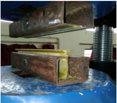
[image:5.595.329.514.56.222.2]As shown in Fig.10 the Universal Testing Machines (UTM): In this project we are choose UTM for physical testing of the specimen. UTM is used for taking four type of material test and my project test is tensile test. Universal Testing Machines are named Because they can perform many different varieties of test on the material. The another name UTM is material testing machine and machine can used to test tensile and compressive properties of materials.They can perform the various operation on same machine such as tension, compression, bending etc to examine mechanical properties of the material this type of machine is called as UTM. There are two type of machines available in market like single column and two column in our project using two column machine. Digital display and extensometers are used for measuring the force and deformation which can also presented in graphical form in computer operated machine.These machine are widely used in industry and all material testing laboratory.
[image:5.595.322.522.154.337.2]Fig.10. Experimental set up for tensile test of I-Beam UTM
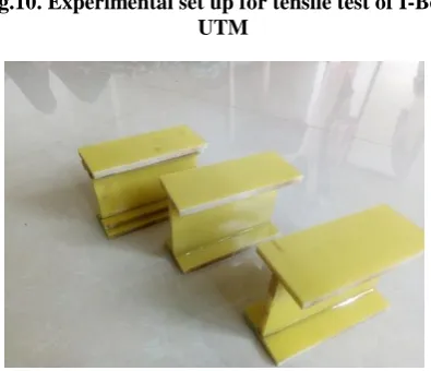
Fig.11 Manufactured sample of I-Beam
As shown in above Fig.11 the actual manufactured specimen of I-beam and which is used for the testing.
1st Sample I-beam with adhesive araldite 2015
As shown in below Fig.12 and Fig 13 the composite I-beam with araldite 2015 before and after testing. Test is a tensile test the load is applied to hydraulic pressure.
[image:5.595.67.271.288.640.2] [image:5.595.66.273.289.453.2]Fig.12. I-beam with adhesive araldite 2015 before test
Fig.13.I-beam with adhesive araldite 2015 after test 2nd Sample I-beam with adhesive Hundsman araldite As shown in below Fig.14 and Fig 15 the composite I-beam with Hundsman araldite before and after testing.
Fig 14.I-beam with adhesive Hundsman araldite before test
[image:5.595.317.512.403.555.2] [image:5.595.66.264.471.641.2]Table-6:Experimental stress of I-beam Sr.No I-Beam with adhesive Stress (MPa)
1 Araldite 2015 9.54
2 Hudsman Araldite 9.83
As shown in above Table 6 the stress generated of manufactured I-beam with araldite 2015 and Hundsman araldite.
[image:6.595.59.260.182.508.2]Tensile Testing of 3rd I-Beam specimen with 4mm cleat
Fig.16. I-beam with 4 mm cleat before Test
[image:6.595.309.545.290.390.2]Fig 17. I-beam with 4 mm cleat After Test As shown in above Fig.16 and Fig.17 the composite I-beam Hundsman araldite with 4mm cleat before and after testing. Tensile testing of 4th I-Beam specimen with 12mm cleat
Fig.18.Composite I- Beam with 12mm cleat before Test
Fig.19. Composite I-Beam with 12 mm cleat After Test As shown in above Fig.18 and Fig.19 the composite I-beam Hundsman araldite with 12mm cleat before and after testing.
Table-7:Max stress of I-beam with cleat Sr.No I-Beam specimen with different size
cleat
Stress (MPa)
1 I-Beam with hundsman Araldite, 4mm cleat
12.06
2 I-Beam with hundsman Araldite, 12mm cleat
12.46
As shown in above Table 7 the maximum stress sustained by I-beam Hundsman araldite with 4mm and 12mm cleat.
VII. RESULTANDDISCUSSION
[image:6.595.304.546.520.645.2]In this study an attempt is made to calculate the stress concentration at WFJ of joint. Then numerical formulation has been established with the help of emperical formulae and analytically stress is calculated. The stress concentration calculated by analytical method is 10.36 MPa.
Table.8:Maximum Stress concentration of I-Beam at WFJ
Sr.No I-Beam Specimens with Adhesive
ANSYS stress (MPa)
Analytical stress (MPa)
1 I-beam with araldite 2015
10.78 9.54
2 I-beam with Hundsman araldite
10.36 9.83
Table 8 shows that the Ansys and Experimental stress sustained by the I-beam with adhesive araldite 2015 and Hundsman araldite .
[image:6.595.71.268.596.745.2].
Fig.20 Maximum Stress concentration of I-Beam at WFJ
From Table 8 and Fig 20 shows that the Hundsman araldite is better adhesive for joining the WFJ because there is less stress concentratinn as compare to araldite 2015.
In next step to increase the stress and load carraying capacity of composite I-beam hundsman araldite with the help of cleat.Table 9 shows that the Ansys and Experimental stress sustained by I-beam with the different size of cleat. Size of cleat is 4mm and 12mm.
Table-9:Maximum Stress Sustained By I-Beam with cleat
Sr.No I-Beam Hundsman araldite with cleats
ANSYS Stress (MPa)
Analytical Stress (MPa) 1 I-beam with 4mm
cleat
12.96 12.067
2 I-beam with 12mm cleat
13.64 12.46
Fig.21 Maximum Stress Sustained By I-Beam with cleats Fig.21 shows that the graphical representation of Ansys and Experimental stress sustained by I-beam. Table 9 shows that the when we increase the size of cleat then the stress and load carrying capacity of beam.
The physical testing is carried out to verify the results obtained from finite element analysis. From physical testing the observed stress at WFJ of I-beam with hundsman araldite is 9.83 MPa and and with cleat 4mm is 12.06 and 12mm is 12.46 MPa .
All the results obtained in this study are tabulated in following Table.
Table-10: Result summary
Stress MPa
I-beam with FEA Exp
Araldite 2015 10.78 9.54
Hundsman Araldite 10.363 9.83
Hundsman Araldite with 4mm
12.96 12.06
Hundsman Araldite with 12mm
13.64 12.46
Physical testing results of baseline model it is observed that there is only 1.43% difference with FEA results. For the model confirmation testing is to be carried out FE analysis results and physical testing results.
VIII. CONCLUSION
The present work has successfully demonstrated the application of Design of experiment .The final conclusions arrived, at the end of this work are as follows
Composite I-Beam will be best option in chemical factory because there is no reaction with acid. Also, its main advantage is low weight as compared to steel.
The composite I-beam with Hundsman Araldite is better than I-beam with araldite 2015 because there is less stress concentration at WFJ and load carrying capacity is more.
The stress and load carraying capacity of composite I-beam with hundsman araldite can be increased by attaching different size cleats to web-flange junction.
REFERENCES
1. Potter K. D., Davies R., Barrett M., Godbehere A., Bateup L., Wisnom M., and Mills A., “Heavily loaded bonded composite structure: design, manufacture and test of `I' beam specimens” Composite Structures, 2001, 51, 389-399.
2. Khalid Y. A., Sahari B. B., Ali F. A. and Saad E. M. A., “Performance of composite I-beams under axial compression and bending load modes” Materials and Design, 2005, 26, 127-135.
3. Hadi N.S., Yuan J. S., “Experimental investigation of composite beams reinforced with GFRP I-beam and steel bars” Construction and Building Materials, 2017, 144, 462-474.
4. Noor A. E., Al-Moubaraki A. H., “Corrosion Behavior of Mild Steel in Hydrochloric Acid Solutions”, Int. J. Electrochem. Sci., 2014, 3, 806-818.
5. Gagani A. I., Emeric P.V. M. and Echtermeyer A. T., “Immersed interlaminar fatigue of glass fiber epoxy composites using the I-beam method”, JIJF, 2018, 4875.
6. Mariama M., Afendi M., Majid M.S.A, Ridzuan M.J.M., Azmi A.I. and Sultan M.T.H., “Influence of hydrothermal ageing on the mechanical properties of an adhesively bonded joint with different adherends”, Composite: Part B, 2019, 165, 572-585.
AUTHORSPROFILE
Mahesh B. Mane, He is presently PG Student of Design engineering in Dr. D Y Patil School of engineering, Pune. He has published research papers in reputed journals.
Dr. Farook Sayyad, He is presently Professor in mechanical department of Dr. D Y Patil School of engineering, Pune. With nearly two decades of teaching experience, he is author of books Theory of Machine, Dynamics of Machinery, Mechanical Vibration & Noise Engineering. He published more than 30 books for various universities in India. He has published several research papers in national and international reputed Journals and conferences. Also he has published two Patents in Intellectual Property India. He is also a member of various national bodies on technical education and also working as editorial board member and reviewer of various international journals.