1-1-2000
Automated blood sampling system
William Blaine Robertson
Iowa State University
Follow this and additional works at:https://lib.dr.iastate.edu/rtd Part of theEngineering Commons
This Thesis is brought to you for free and open access by the Iowa State University Capstones, Theses and Dissertations at Iowa State University Digital Repository. It has been accepted for inclusion in Retrospective Theses and Dissertations by an authorized administrator of Iowa State University Digital Repository. For more information, please [email protected].
Recommended Citation
by
William Blaine Robertson
A thesis submitted to the graduate faculty
in partial fulfillment of the requirements for the degree of
MASTER OF SCIENCE
Major: Biomedical Engineering
Major Professor: Richard L. Engen
Iowa State University
Graduate College Iowa State University
This is to certify that the Master's thesis of William Blaine Robertson
has met the thesis requirements oflowa State University
TABLE OF CONTENTS
ACKNOWLEDGEMENTS iv
INTRODUCTION 1
LITERATURE REVIEW 2
MATERIALS AND METHODS 3
Hardware 4
Software 17
OPERATION 19
RESULTS 24
DISCUSSION AND CONCLUSION 26
APPENDIX ABSS PROGRAM LISTING 28
ACKNOWLEDGEMENTS
I would like to thank my major professor, Dr. Richard Engen, Professor and Chair of the Veterinary Physiology and Pharmacology Department for his guidance, encouragement and confidence by providing me with the opportunity to undertake this project.
I would also like to thank Dr. Fred Hembrough for his practical advice throughout this endeavor and Dr. Lyle Kesl for his performance of the live animal surgical procedures required during testing of the ABSS. In addition, I would like to thank Dr. Srdija Jeftinia and Dr. Walter Hsu for serving on my graduate committee and Dr. Mary Helen Greer for her advice, guidance and kind supervision of my progress.
In addition, while I designed and built the majority of the ABSS, four other people need to be given credit for their assistance. Kyle Holland for designing the valve driver circuitry and Tim Modeland, the machinist that constructed the ABSS support frame to exact specifications and improved the mechanical design of several aspects of the system. Mark Tschopp for writing the initial Visual Basic code that controlled the system, and Bob Matura (a programming genius) for improving the initial code.
Researchers in the pharmaceutical industry regularly conduct drug studies using laboratory animals. The pig is a commonly used animal in these studies for a variety of reasons: it is readily available, easy to care for, etc. One drawback; however, is the fact that the pig is easily excitable. Excitation is induced in a pig each time a laboratory technician arrives to draw a blood sample, something that can occur several times over the course of a single study. This excitation results in the pig experiencing an increase in heart and
respiration rate, elevated blood pressure, etc. This in tum results in metabolic changes [7] and has nothing to do with the drug study, but raises the issue of the effect on the results and validity of the study. The Automated Blood Sampling System (ABSS) was developed to eliminate this factor.
The ABSS was designed to allow the researcher to administer a test drug to the pig and then leave the room, the system would then automatically take and store individual blood samples at predetermined times. Without the researcher or technician in the room, the pig would remain calm, oblivious to the fact that blood samples were being drawn periodically.
Several initial designs for the ABSS were formulated and considered as parameters and requirements changed. Eventually the design described in this paper was agreed upon. In the first section, a literature review is provided to highlight the advances in robotic or automated sampling systems to date. The second section provides an overview of the function of each of the hardware components and software interface involved in the
LITERATURE REVIEW
Today's modem integrative physiology calls for data with high signal-to-noise ratios. Signal-to-noise is generally thought of in regards to electrical recordings; however, it can also be a factor where data may be affected by external influences. These data can only be
obtained if the organisms under study, usually animals, remain undisturbed from exogenous (outside) influence [ 4]. A voiding the presence of humans near the animals prevents social interactions (positive or negative) that might produce biochemical changes [5].
Several precautions are necessary to reach this goal. Environmental conditions should be as free as possible of unwanted disturbances, and data collection should be made without animals being aware of the collection [ 4]. Further, an automated collection system allows the collection of samples simultaneously from all subjects [5].
The majority of existing automatic blood sampling systems have been designed for use with unrestrained animals. These devices have been used to collect samples from a variety of animals: ducks and hens [7], pigs [6], baboons [5], running greyhounds [8], and free-diving Weddell seals [2]. Each of these devices used a different method to collect and store a blood sample.
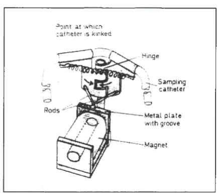
Scheid and Slama collected and stored blood from ducks and hens in a sampling catheter by simply kinking the catheter automatically with a spring-loaded hinge, shown in Figure 1. The device collected one sample at a time, and operated by manually switching off an electromagnet with a remote control [7].
=
?01nt at which catneter 1s kinked
Figure 1. Spring-loaded hinge
12
l
.
-ra
0 , 'LJ
13 14
'\ L
SamplingW ~atheter
f1
-'d
Metal plate with groove
3
Figure 2. Continuous collection system
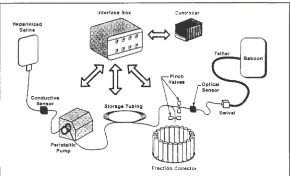
[image:8.568.93.310.79.272.2] [image:8.568.94.378.333.674.2]Rogers et al. collected blood samples from tethered baboons, shown in Figure 3,
through the use of a peristaltic pump and fraction collector. The collection system, shown in
Figure 4, would draw blood from the animal into a coil of tubing. When a conductive sensor
indicated the tubing was full, automatic valves were actuated and the peristaltic pump
reversed, this pushed the blood out of the coil of tubing into the fraction collector.
Figure 3. Tethered Baboon
Conductive Sensor
Figure 4. Collection system
Tether
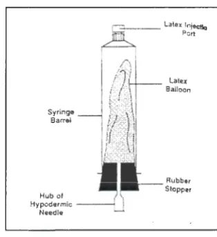
[image:9.570.94.316.210.419.2] [image:9.570.98.396.484.665.2]Schmalzried et al. collected a total of eight samples from a running greyhound. The
samples were collected using a latex balloon as a reservoir within an evacuated 20-ml plastic
syringe, shown in Figure 5. Each syringe was attached to an automatic valve and actuated by
a micro-controller [8].
.- _ _ Latex lniectlc) ' ~ . Pert
, .. ,. 1 - - 1 - - - - Latex
Syringe Barrel
Hub of 1 \
Hypodermic ~ i
Needle __;.
Figure 5. Collection reservoir Balloon
Rubb&r
Stopper
Hill's device was a multiple-sample collector, and collected a total of eight samples
from free-diving Weddell seals during a single dive. The samples were collected through the
use of a battery-operated peristaltic pump and stored in 20-ml syringes [2].
While each of these methods had advantages, none allowed for the versatility of
easily varying the number of samples, sample interval, and sample volume. Such versatility
is required if the system is to be used in long-term studies and with different species. It was
this criterion most of all that led to the development of the Automated Blood Sampling
System. Initially, two parameters were conceived: 1) Blood samples needed to be collected
and stored in individual containers that were readily available, and 2) A positioning system
was required that could automatically progress from one individual sample container to the
next with precision. To meet these parameters, the following two solutions were adopted:
1) Glass evacuated blood-drawing tubes (Vacutainers®) have been the standard
[image:10.569.93.250.192.363.2]Vacutainer will draw just enough blood to fill itself, and it is impossible to overfill it, even when the blood is under relatively high pressure. Since Vacutainers can be purchased in a variety of sizes, this allows a precise volume of blood to be taken easily and quickly.
2) A stepper motor is a special type of motor that lends itself to precise positioning under digital computer control [10). The MD-2 Dual Stepper Motor Package from Arrick Robotics provides all of the components necessary to operate stepper motors from an IBM compatible personal computer. The MD-2 package includes motor driver electronics, power supply, motor cables, software, and documentation. To provide three-axes positioning, an 18-inch XY table and a 2-inch Z table are also available from Arrick Robotics.
MATERIALS AND METHODS
Hardware
The ABSS was constructed with as many "off-the-shelf' commercially available parts
as possible in order to reduce costs and expedite design and assembly time. When
necessary; however, custom parts were fabricated. The following section details the
materials and methods used in the construction of the ABSS and how each segment of the
system works.
In a research animal laboratory where blood is drawn on a regular basis, a catheter is
placed inside a blood vessel to avoid the need to puncture the animal's skin repeatedly with a
hypodermic needle. Blood is drawn out of the animal, through this catheter, by a vacuum.
This vacuum can be generated by something as simple as manually pulling back on the
plunger of a syringe or connecting the catheter to a Vacutainer. Vacutainers are commonly
available in various sizes and can be purchased pre-treated with Ethylenediamine-tetraacetic
acid (EDTA), a blood anticoagulant that prevents the blood sample in the tube from clotting.
The ABSS expands on the use ofVacutainers by automating the collection process.
Like a human laboratory technician, the ABSS connects the catheter in the pig to a
Vacutainer using a hypodermic needle. Unlike a human technician that places one
Vacutainer after another on the stationary hypodermic needle, the ABSS moves the
hypodermic needle from one stationary Vacutainer to the next.
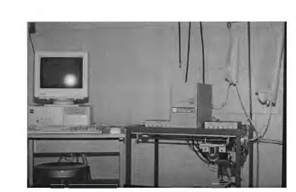
A schematic of the ABSS is shown in Figure 6 and photograph of the complete
Saline Support
•
PC~
Valve driver c:::::J
• . /
Motor driver
1
Z -axis
l
X a x i s
-Figure 6. Automated Blood Sampling System
Figure 7. Automated Blood Sampling System
[image:13.571.97.455.72.314.2] [image:13.571.54.473.352.624.2]-The general operation of the ABSS is as follows. -The researcher determines the
number of catheters (six total) required for the study and connects the catheter(s) coming
from the pig to automatic valves on the ABSS as diagramed in Figure 8. An acrylic rack on
the bottom of the ABSS, shown in Figure 9, is loaded with Vacutainers, one for each blood
sample.
Sterile Salinerush Solution
6-Port Valve
\
BFigure 8. Catheterized pig connected to valve #1 of the six-port valve.
[image:14.568.96.407.216.427.2] [image:14.568.51.424.284.684.2]The sample-time intervals desired are entered into the computer software and the
program started. At each sample-time, the computer starts a sampling cycle. During the
sampling cycle, an XYZ coordinate positioning system (supported on the frame above the
rack of Vacutainers) automatically moves the hypodermic needle into position directly above
the appropriate Vacutainer. The hypodermic needle is driven into the Vacutainer and the
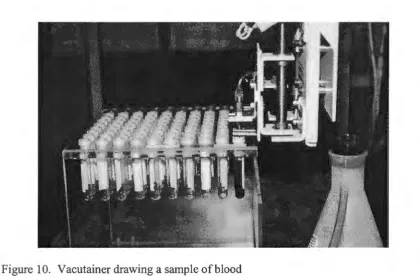
blood sample taken as shown in Figure 10. The sampling cycle is repeated at each successive
sample-time.
Figure 10. Vacutainer drawing a sample of blood
Although the ABSS is positioned as close to the pig as possible, it is necessary to
draw blood through a length of polyethylene tubing connecting the catheter in the pig to the
hypodermic needle that punctures the Vacutainer rubber stopper or septum. Several tests
were conducted to prove that various size Vacutainers could draw blood through the catheter
[image:15.569.55.473.263.541.2]Before each blood sample is collected, the catheter and tubing must be primed, i.e.
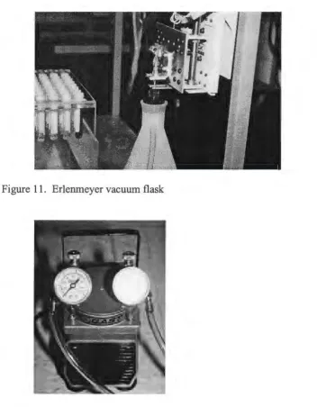
filled with blood. This is accomplished by driving the hypodermic needle through a silicon
septum on the top of a plastic 2-liter Erlenmeyer vacuum flask, shown in Figure 11. A small
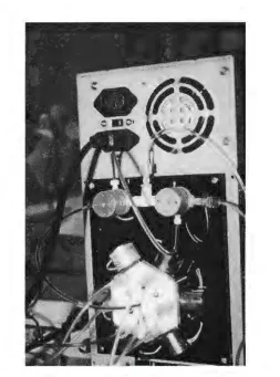
electric pump, (Gast, model DOA) shown in Figure 12, is used to maintain a vacuum on the
Erlenmeyer flask. As the vacuum pulls the blood from the pig, the flush solution present in
the catheter and tubing is expelled into the Erlenmeyer flask.
[image:16.567.54.406.244.696.2]Figure 11. Erlenmeyer vacuum flask
Once the catheter and tubing are primed all the way down to the hypodermic needle,
the software instructs the XYZ coordinate positioning system to move the hypodermic needle
to the appropriate Vacutainer and the blood sample is taken.
After each sample is taken, the catheter, tubing and hypodermic needle must be
flushed to prevent the blood from clotting and causing a blockage. Again, the hypodermic
needle is moved by the XYZ coordinate positioning system into the Erlenmeyer vacuum
flask where the vacuum pulls a flush solution through the valves, tubing and hypodermic
needle from a bag of sterile saline. The sterile saline flush solution was purchased in a 3-liter
bag, placed in a pressure cuff and hung from a support rod attached to the ABSS frame,
shown in Figures 6 and 7. The catheter in the pig needs to be flushed as well. This is
accomplished by pushing the blood in the catheter back into the pig with pressurized sterile
saline flush solution. To maintain constant flush solution pressure the saline bag is placed
inside an inflatable pressure cuff. The same small electric pump shown in Figure 12,
performs the dual purpose of supplying the vacuum necessary for the Erlenmeyer flask and
inflating the pressure cuff for the saline flush solution. Between samples, the catheter and
tubing remain filled with flush solution.
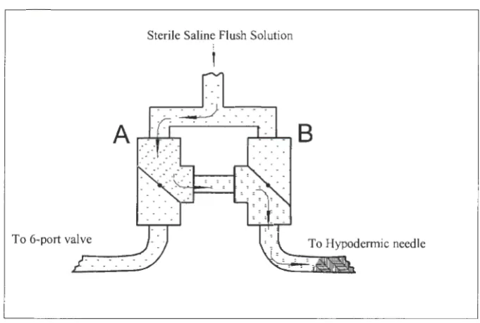
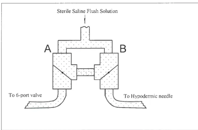
Automatic valves, shown in Figures 13 and 14, control the flow of blood and flush
solution. Two of these valves (A and B) are three-way Teflon PTFE solenoid valves (Cole
Parmer, CP# 01367 - 72) connected together in such a way that the pressurized saline can be
flushed back into the pig or toward the hypodermic needle in the Erlenmeyer flask, Figures
15 and 16. The large radial valve is a six port Teflon PTFE solenoid manifold valve (Cole
Parmer, CP# 01367 - 83). This valve provides the means to connect the ABSS to four pigs
Sterile Saline Flush Solution
I
6-Port Valve
[image:18.570.97.444.72.306.2]\
Figure 13. Catheterized pig connected to inlet valve #1
[image:18.570.76.330.352.693.2]Sterile Saline Flush Solution
j
To 6-port valve
Figure 15. Blood being flushed back into pig
Sterile Saline Flush Solution
I
[image:19.567.99.438.78.302.2]To 6-port valve
[image:19.567.96.437.374.603.2]The positions of valves A and B between samples and during a sample-time are
shown in Figures 17 and 18.
Solid state relays are required to control each of the eight valves. A relay board with
eight relay sockets, eight relays, an I/O board and a ribbon cable were purchased from
CyberResearch, Inc. The I/O board was installed in the IBM compatible PC and a ribbon
cable was used to connect the I/O board with the relay board.
Each of the valves require 12-volts to actuate; however, the valve manufacturer
recommended that voltage be reduced to approximately 4-volts to prevent overheating if the
valves are to remain energized for more than two minutes. This was accomplished through
the design and construction of the custom valve driver circuit shown in Figure 19. The
schematic for the circuit is shown in Figure 20. A microcomputer tower case and internal
power supply was purchased to house and power the valve driver circuitry, relay board and
relays.
Sterile Saline Flush Solution
i
[image:20.569.98.430.438.656.2]To 6-port valve To Hypodermic needle
Sterile Saline Flush Solution
f
B
[image:21.567.98.475.73.326.2]From 6-port valve
Figure 18. Blood sample being drawn to hypodermic needle
[image:21.567.54.511.264.631.2]Figure 20. Valve driver schematic
! _1_
hi
r
~
~
L
...
li~::,:
l
-iN~1H
+t2V
I Vc1t~ge
Drop
I Beard
lrie;ay !Beare
The XYZ coordinate positioning system used to move the hypodermic needle was
purchased from Arrick Robotics. This consisted of an XY-18 table, a Z-2 table and BR-2
right angle mounting bracket for vertical mounting of the Z-2, shown in Figures 21 and 22.
These tables mounted together and fastened to the ABSS frame serve to move the
hypodermic needle in the XY and Z directions.
Two MD-2 Dual Stepper Motor Systems including the stepper motors, three motor
cables and motor controller software, shown in Figure 23, were also purchased from Arrick
Robotics. This eliminated any incompatibility problems associated with trying to interface
the stepper motors to the computer software.
Figure 21. XY - axis coordinate positioning tables
Figure 23. MD-2 Dual Stepper Motor Systems
Table 1. Hardware List
IBM compatible personal computer with monitor, keyboard, and mouse Second parallel 1/0 card and two parallel 1/0 cables
Digital 1/0 board
XY-18 table
Z-2 table and BR-2 right angle mounting bracket
2-MD-2 Dual Stepper Motor Systems, includes 4 stepper motors and 3 motor cables
Frame: approximately 29.S"W X 22"0 X 29.75"H
100 Tube Plexiglas Vacutainer rack, large diameter Vacutainers
Erlenmeyer flask w/vacuum port and stopper assembly
Stopper assembly: large rubber stopper w/hole, syringe barrel, silicon septum
Electric vacuum /compressor pump
Valve driver housing/support 5 and 12 volt power supply Relay board w/8 relays Voltage drop board
2-three-way Teflon PTFE solenoid valves I-six-port Teflon PTFE solenoid manifold valve
Pressure cuff for 3-liter sterile saline bag
Hypodermic needle (16 gauge) and mounting bracket
Polyethylene connection tubing
Various diameter catheters
(CyberResearch, Inc.)
(Arrick Robotics)
(Modeland Machine)
(Gast, model DOA)
(CyberResearch, Inc.)
[image:24.567.48.508.50.716.2]Software
The first requirement for the ABSS software was that it should be user-friendly. The
assumption was made that the technicians using this application may have had little computer
experience. The decision to use Visual Basic was made after reviewing the Visual Basic
Programmer's Guide [11]. Visual Basic provided the programmer with the ability to create
screen forms very quickly and easily. The form design tool was object oriented and allowed
the programmer to easily place text fields, command buttons, labels, menu bars, etc. on the
screen form. This eliminated the need to write the code necessary to create these features;
only the code that executed the features needed to be written (event-driven programming).
This allowed the programmer to create a user interface that was simple to use [9].
The program was divided into three modules, each of which contains several sub
procedures. Declaration of sub procedures, variables, arrays, etc. are included at the module
level. The CMNDLG.BAS and CMNDLGF.FRM modules are provided with Visual Basic.
These modules were used to acquire the necessary file information needed to save and
retrieve sample times from a data file. The software provided by Arrick Robotics to control
the stepper motors is contained within the (take_sample) procedure.
Visual Basic executes certain procedures automatically when a specific event occurs.
For example, when the menu option New (CtlName = mnu_new) is chosen by the user, by
clicking on it, Visual Basic automatically performs the sub procedure (mnu_new_click) if it
is present. The sub procedure (form_load) is performed automatically when the program is
run; this allows the programmer to set initial screen parameters, variables, or perform
listing is found in the Appendix. The compiled assembly language program provided with
the I/0 board was used to create a .QLB file to be used by the Visual Basic program. The
autoexec.bat file on the PC was modified to start the ABSS application automatically when
the PC was turned on.
Extreme care was taken to assure that the Vacutainer rack was positioned square with
the XY table. This allowed for the development of two equations for positioning the
hypodermic needle above any of the Vacutainers and eliminated the need to find the location
of each Vacutainer by trial and error and then store the values for future reference. Each
Vacutainer center is located 170 motor steps, in the X or Y direction, from the center of the
Vacutainer adjacent to it. The following equations were used to position the hypodermic
needle based on the tube number:
COLUMN (X axis)= ((tube -1 ) mod 10) * 170
ROW (Y axis)= 1070 + ((tube - 1 ) \ 10) * 170
where, tube 1 is in row 1, column 1 (innermost, rightmost tube), tube 2 is in row 1, column 2,
OPERATION
The following section describes the steps necessary for operation of the ABSS.
All of the cables should be connected as described in the manufacturer's manuals. The IBM
compatible PC should be turned on first, followed by the stepper motor drivers, the valve
driver housing and the small electric pump.
The ABSS program will appear on the computer screen showing the user interface.
Initially, the screen shows four rows with twelve squares in each row. Each square is labeled
pig # 1 through pig #4. The sampling times are entered in these squares. In order to enter a
time in a particular square, move the mouse pointer to that square and click on it. The cursor
will appear in the square and the user can enter a sampling time. The Tab key can also be
used to move from square to square while entering sampling times. The sampling times are
entered in minutes from time zero, i.e. the number of minutes after sampling has started. For
example, if a sample is to be taken an hour and a half after sampling starts, 90 would be
entered in the appropriate square. Fractions of minutes are expressed with a decimal. No
squares should be left blank between sampling times in any particular row.
A mode command button is located near the top of the screen at all times. This
button allows the user to switch between the using four pigs with one catheter each or two
pigs with three catheters each. When the program mode is set to sample using one catheter
per pig, all four pigs are listed on the screen and the button is labeled "4 pigs w / 1 catheter".
Clicking the mode button allows the user to switch to sampling from two pigs with three
catheters in each. In the three catheters mode, only pig #1 and pig #2 are listed on the screen,
A menu bar is located at the top of the screen with three selections: File, Options and
Run. When each of these selections are clicked, a drop down menu will reveal several
options, shown in Table 2.
The File selection drop down menu contains the options: New, Open, Save, and Exit.
The New option clears the current times for all pigs and all squares are shown blank. A
warning window appears before clearing to verify that the user wants to erase the current
sampling times. The Open option allows the user to retrieve previously saved sampling times
from disk. A window requesting the file, path, and drive will also appear for this option.
The Save option stores the current sampling times in a data file on disk. A window appears
to request the file name and path as well as the drive, C or A (internal or 3.5 inch floppy
drive, respectively). The Open and Save options allow the user to enter a set of frequently
used sampling times once, save the times, and then retrieve them whenever necessary.
The Exit option stops the application and returns the user to Visual Basic.
Table 2. Drop Down Menu Options
File New Open Save Exit
Options
Run
Show Clock Check Times Show Wait Times
Start Sampling Prime
[image:28.565.74.503.466.695.2]Before exiting the application, a warning window appears giving the user a last chance to
save any sampling times that are currently entered.
The Options drop down menu contains three choices: Show Clock, Check Times, and
Show Wait Times. The Show Clock option allows the user to toggle on/off the display of the
PC system clock.
The Check Times option allows the user to verify that the sample-times entered meet
system requirements. This check is necessary because each catheter requires a minimum of
two minutes to prime, take sample, flush and get ready for the next sample. The two minute
minimum is sufficient in the "4 pigs w / 1 catheter" mode, but in "2 pigs w / 3 catheters"
mode, there must be at least six minutes between sample-times (two minutes for each
catheter). If the sample-times meet the system requirements, a message is displayed in a
window indicating the approval. If the sample-times do not meet the system requirements, a
message is displayed indicating that times must be altered before sampling can begin.
Included in the message is a suggestion as to which pigs and columns the user should
examine to correct the problem.
The Show Wait Times option will be discussed after the sampling operations have
been described.
The Run drop down menu contains three choices: Start Sampling, Prime, and Shut
Down. The Start Sampling option automatically executes the Check Times routine to verify
that the sample-times meet system requirements. If the sample-times meet system
requirements, the time that sampling began is displayed on the screen above the current time.
From this point on, the program waits for the next sample-time to occur. The sample-times
occurs, the sample-time number on-screen changes color from black to red. This serves as a
quick indicator as to which sample is being processed. The catheter and tubing are primed,
the blood sample taken, and the lines flushed as described in the hardware section. At the
end of the sample-time the sample-time number changes color again, this time from red to
green, indicating samples that have been completed.
At the end of a sample-time all stepper motors are powered down (motors' phases are
turned off), keeping the motors and dual stepper motor drivers cool. The six-port valve,
regrettably, is not a zero dead space valve; and some residual blood can remain in the valve.
To remove this blood and avoid damaging the valves, all six ports are opened simultaneously
and flushed with pressurized sterile saline. Because of this routine, tubing must always be
connected to each port on the six-port valve and all unused lines placed in a container.
The third option in the Options drop down menu is the Show Wait Times. This
option allows the user to modify time delays for priming, flushing, and agitating the system.
When the Show Wait Times option is selected, a table of delay times will appear below the
rows of sample-times. The delay times mentioned above can be set individually for each of
the six catheters. The prime-time delay is the time that the hypodermic needle remains in the
Erlenmeyer flask at the beginning of sampling. The flush-time delay is the amount of time
that saline is pushed back into the pig. The agitate-time delay is the time required to flush
out the six-port valve.
The catheter size, the blood vessels (arteries or veins), and the pigs' blood pressure are
all possible factors that may require the user to adjust the delay times. A small diameter
catheter will not allow as great a blood flow as a large diameter catheter for a given amount
flushed for a longer period to obtain the same volume. When sampling from an artery or a
pig with high blood pressure, less time is needed to draw blood, but more time is needed to
push blood and saline back into the pig.
The second option in the Run drop down menu is Prime. This routine should be
performed before any catheters are connected to the pigs. The Prime routine will draw saline
through all six tubes connected to the six-port valve to remove any air and fill the lines with
saline. All six catheters should be placed in a large container of saline and then click the
Prime option. The pressurized saline bag forces saline through all six of the catheters for
approximately 5 seconds each, all of the valves are then closed. At this point, the catheters
can be connected to the pigs; any unused catheters should remain in the saline container as
described earlier.
The third option in the Run drop down menu is Shut Down. This routine should be
performed when sampling is completed. The valves must be flushed with sterile water to
remove the saline since it is possible for salt to precipitate out of the saline and damage the
valve diaphragms. Before this option is chosen, the saline bag should be replaced with a bag
of sterile water. The tubes connected to each port of the six port valve and the tube
connected to the hypodermic needle should be placed into a container to collect the sterile
water. When the shut down option is chosen, sterile water is flushed through each tube for
ten seconds. The flushing of each of these seven tubes is repeated four times and then all
valves are closed.
The PC, dual stepper motor drivers, small electric pump, and valve driver housing are
RESULTS
The following describes the procedures used to test the ABSS, the results of which
lead to improvements and additions to the software.
The system was first tested using one one-liter flask of dog blood that had been
heparinized to prevent it from clotting. The blood in the flask was heated to 37 °C to
simulate normal body temperature. The flushing and sampling periods were adjusted to
collect the sample without wasting saline, or blood. During this testing it was discovered that
some residual blood was left in the six-port valve after the initial flushing. The additional
flushing routine described in the Operation section was then developed and the problem
corrected. The second test involved six 250-ml flasks of heparinized dog blood. This test
simulated six different catheters and was performed to determine if there was a substantial
difference in timing or volume delivered by individual ports on the six-port valve. When the
results proved there was little difference between ports, it was decided to proceed with testing
the ABSS on a live animal.
A 70-pound greyhound was anesthetized and a catheter placed in both femoral veins
and both jugular veins to simulate four pigs with one catheter each. One of the ports was
attached to a Swans Ganz catheter to check system performance with a smaller lumen. As
expected, much more time was required to draw and push blood through this smaller
diameter catheter. A new software option was developed to allow the operator to adjust the
timing for each catheter independently depending on catheter size and blood vessel pressure.
The Show Wait Times option was also added.
time delays could now be changed so that a Swans Ganz catheter would sample and flush
correctly. Blood samples from the first greyhound indicated hemolysis, so the hypodermic
needle was changed from an 18 gauge to 16 gauge during the second greyhound testing. This
larger gauge needle reduced hemolysis to an acceptable level.
Several other operational concerns appeared during testing. Vacuum grease was
required at all tubing connections to provide an airtight system. A three-liter Erlenmeyer
flask partially filled with saline was necessary to prime the system and hold any unused
catheters. All catheters were placed in this container when sampling was finished and the
shut down routine flushed the system with sterile water.
Final testing of the ABSS was conducted on a 50-pound pig confined in a holding pen
that allowed the pig to stand or lie down, but prevented motion in any other direction. This
allowed the pig to be conscience while preventing the pig from inadvertently pulling the
DISCUSSION AND CONCLUSIONS
The ABSS was a design prototype that worked! The system successfully
accomplished exactly what it was designed to do, i.e. automatically take multiple blood
samples from a laboratory animal without operator intervention. Considering the complexity
of the task and the lack of previous work from which to draw, this project was an enormous
success. This does not mean however, that improvements cannot be made. As with most
initial endeavors, hindsight is 20/20.
The following are suggestions for improvements that the author believes will increase
the likelihood of automatic blood sampling systems becoming a commonplace instrument in
laboratories conducting long-term blood studies.
The initial improvement to the ABSS would be to decrease the size of the system.
Increased portability would make the instrument far more attractive to many researchers
conducting studies on a variety of species. Tabletop XYZ positioning systems are
commercially available at present and operate with far more reliability than those selected for
this project. Many of these systems have on-board micro-controllers that would eliminate the
need for an external computer.
Valves with zero dead space should be used in place of the diaphragm valves chosen
for this project. Pinch valves (valves that simply pinch tubing to stop flow) would be an
excellent choice since blood would never enter the interior of the valve. This would
eliminate the dead space problem encountered, and reduce the amount of turbulence (hence
hemolysis) produced by a diaphragm type valve. Further, in the event blood was not flushed
System feedback would be an extremely important improvement to the ABSS.
Feedback would allow the system to actively monitor the presence of blood in the connection
tubing and control the sampling accordingly. This presents a large technical challenge, but if
solved would increase the reliability of an automated sampling system several times over.
The last suggestion is not critical to system performance, but raises the issue of a
general power outage. While the pig would not bleed to death, the system itself may be
APPENDIX
ABSS PROGRAM LISTING
DECLARE FUNCTION TIMEEXPIRED (T, D AS STRING, S AS SINGLE) AS SINGLE DECLARE SUB DELA YFOR (S AS SINGLE)
DECLARE FUNCTION Smallest (i!, A!, B!, C AS SINGLE) AS SINGLE DECLARE FUNCTION Adj (S AS STRING) AS SINGLE
DECLARE SUB valve_flush () DECLARE SUB mnu _save_ click ()
DECLARE SUB FileSave (FileName AS STRING, PathName AS STRING, DefaultExt AS STRING, DialogTitle AS STRING, forecolor AS INTEGER, BackColor AS INTEGER, Flags AS INTEGER, cancel AS INTEGER)
DECLARE SUB FileOpen (FileName AS STRING, PathName AS STRING, DefaultExt AS STRING, DialogTitle AS STRING, forecolor AS INTEGER, BackColor AS INTEGER, Flags AS INTEGER, cancel AS INTEGER)
DECLARE SUB chk_time (min_delay AS INTEGER, ok AS INTEGER) DECLARE SUB timerl_timer ()
DECLARE SUB md2_init ()
DECLARE SUB take_sample (tube AS INTEGER, valve AS INTEGER) DECLARE SUB four_hog ()
DECLARE SUB two_ hog ()
DECLARE SUB CIODIO (MD AS INTEGER, BYV AL ARR AS INTEGER, F AS INTEGER)
DIM T%(5) DIM D%(10)
COMMON SHARED D¾()
DIM SHARED cancel AS INTEGER DIM SHARED FileName AS STRING DIM SHARED PathName AS STRING DIM SHARED BACKLASH%(6) DIM SHARED CHECK.KEY$(6) DIM SHARED CHECK.SWITCH$(6) DIM SHARED CURRENT.POSITION&(6) DIM SHARED DIRECTION$(6)
DIM SHARED MD2.LAST.DIRECTION$(6)
DIM SHARED MD2.LAST.PATTERN%(6)
DIM SHARED MD2.PATTERN%(8)
DIM SHARED MD2.NEW.PATTERN%(8) DIM SHARED POWER.DOWN$(6)
DIM SHARED SPEED%(6)
DIM SHARED STEPS.TO.MOVE&(6) DIM SHARED step.type$(6)
DIM SHARED TARGET.POSITION&(6)
FUNCTION Adj (S AS STRING) AS SINGLE
IF V AL(S) = 0 THEN Adj = 9999 IF V AL(S) <> 0 THEN Adj = V AL(S)
END FUNCTION
SUB chk_time (min_delay AS INTEGER, ok AS INTEGER)
' Procedure verifys that all times entered in the sampling ' times squares are at least min_ delay minutes apart from ' every other time. ok is passed back to the calling ' procedure to indicate the result of the checking routine. ' ( ok= 1 times approved, ok=0 times must be changed before ' sampling can begin.)
'cdt : Catheter Delay Totals, ie waste+flush+pull+push OPEN "c:\times.txt" FOR INPUT AS #1
INPUT #1, TDl INPUT # 1, TD2 INPUT #1, TD3 INPUT # 1, TD4 INPUT #1, TD5 CLOSE #1
st = TD 1 + TD2 + TD3 + TD4
sixwaypush = VAL(push(0).text) + V AL(push(l).text) + VAL(push(2).text) + VAL(push(3).text) + VAL(push(4).text) + VAL(push(5).text)
cdtl =(st+ V AL(waste(0).text) + VAL(flush(0).text) + V AL(pull(0).text) + sixwaypush) /
60
cdt2 =(st+ VAL(waste(l).text) + VAL(flush(l).text) + VAL(pull(l).text) + sixwaypush) /
60
cdt3 =(st+ VAL(waste(2).text) + V AL(flush(2).text) + VAL(pull(2).text) + sixwaypush) /
60
cdt4 =(st+ V AL(waste(3).text) + V AL(flush(3).text) + VAL(pull(3).text) + sixwaypush) /
60
cdt5 =(st+ VAL(waste(4).text) + VAL(flush(4).text) + V AL(pull(4).text) + sixwaypush) /
60
cdt6 =(st+ V AL(waste(5).text) + VAL(flush(5).text) + VAL(pull(5).text) + sixwaypush) /
60
IF min_ delay = 6 THEN cdt2 = cdt4 + cdt5 + cdt6
FOR i = 0 TO 11 FORj = 0 TO 11
IF i <j THEN IF ((VAL(textl(i).text) + cdtl) > VAL(textl(j).text) AND
VAL(textl(i).text) <> 0 AND VAL(textl(j).text) <> 0) OR (V AL(textl(i).text) = 0 AND
V AL(textl(i + 1).text) <> 0) THEN response¾= MSGBOX("The current times do not meet
system requirements. Sampling cannot begin until times are modified. Please examine pig
#1, columns"+ STR$(i + 1) +"and"+ STR$(j + 1), 0, "Warning"): ok = 0: IF response¾=
1 THEN GOTO done
IF ((V AL(textl(i).text) + cdtl) > V AL(text2(j).text) AND (VAL(textl(i).text) - cdtl)
< V AL(text2(j).text)) AND VAL(textl(i).text) <> 0 AND VAL(text2(j).text) <> 0 THEN
response¾ = MSGBOX("The current times do not meet system requirements. Sampling
cannot begin until times are modified. Please examine pig # 1 and pig #2, columns " +
STR$(i + 1) +"and"+ STR$(j + 1), 0, "Warning"): ok = 0: IF response¾= 1 THEN GOTO done
IF ((VAL(textl(i).text) + cdtl) > VAL(text3(j).text) AND (VAL(textl(i).text) - cdtl)
< VAL(text3(j).text)) AND VAL(textl(i).text) <> 0 AND V AL(text3(j).text) <> 0 THEN
response¾ = MSGBOX("The current times do not meet system requirements. Sampling
cannot begin until times are modified. Please examine pig #1 and pig #3, columns"+
STR$(i + 1) +"and"+ STR$(j + 1), 0, "Warning"): ok = 0: IF response¾= 1 THEN GOTO done
IF ((VAL(textl(i).text) + cdtl) > V AL(text4(j).text) AND (VAL(textl(i).text) - cdtl)
< V AL(text4(j).text)) AND VAL(textl(i).text) <> 0 AND VAL(text4(j).text) <> 0 THEN response¾ = MSGBOX("The current times do not meet system requirements. Sampling cannot begin until times are modified. Please examine pig #1 and pig #4, columns"+
STR$(i + 1) +"and"+ STR$(j + 1), 0, "Warning"): ok = 0: IF response¾ = 1 THEN GOTO
done
IF i < j THEN IF ((VAL(text2(i).text) + cdt2) > VAL(text2(j).text) AND
VAL(text2(i).text) <> 0 AND V AL(text2(j).text) <> 0) OR (V AL(text2(i).text) = 0 AND
VAL(text2(i + 1).text) <> 0) THEN response¾= MSGBOX("The current times do not meet
system requirements. Sampling cannot begin until times are modified. Please examine pig
#2, columns"+ STR$(i + 1) +"and"+ STR$(j + 1), 0, "Warning"): ok = 0: IF response¾=
1 THEN GOTO done
IF ((V AL(text2(i).text) + cdt2) > VAL(text3(j).text) AND (VAL(text2(i).text) - cdt2)
< VAL(text3(j).text)) AND VAL(text2(i).text) <> 0 AND VAL(text3(j).text) <> 0 THEN response¾ = MSGBOX("The current times do not meet system requirements. Sampling cannot begin until times are modified. Please examine pig #2 and pig #3, columns"+ STR$(i + 1) +"and"+ STR$(j + 1), 0, "Warning"): ok = 0: IF response¾= 1 THEN GOTO done
IF ((V AL(text2(i).text) + cdt2) > V AL(text4(j).text) AND (VAL(text2(i).text) - cdt2)
< V AL(text4G).text)) AND V AL(text2(i).text) <> 0 AND V AL(text4G).text) <> 0 THEN response¾ = MSGBOX("The current times do not meet system requirements. Sampling
cannot begin until times are modified. Please examine pig #2 and pig #4, columns " +
done
IF i < j THEN IF ((VAL(text3(i).text) + cdt3) > VAL(text3(j).text) AND
VAL(text3(i).text) <> 0 AND VAL(text3(j).text) <> 0) OR (VAL(text3(i).text) = 0 AND
VAL(text3(i + 1).text) <> 0) THEN response%= MSGBOX("The current times do not meet
system requirements. Sampling cannot begin until times are modified. Please examine pig #3, columns"+ STR$(i + 1) +"and"+ STR$(j + 1), 0, "Warning"): ok = 0: IF response%= 1 THEN GOTO done
IF ((V AL(text3(i).text) + cdt3) > V AL(text4(j).text) AND (VAL(text3(i).text) - cdt3)
< VAL(text4(j).text)) AND V AL(text3(i).text) <> 0 AND VAL(text4(j).text) <> 0 THEN
response% = MSGBOX("The current times do not meet system requirements. Sampling cannot begin until times are modified. Please examine pig #3 and pig #4, columns " + STR$(i + 1) +"and"+ STR$(j + 1), 0, "Warning"): ok = 0: IF response%= 1 THEN GOTO done
IF i < j THEN IF ((VAL(text4(i).text) + cdt4) > VAL(text4(j).text) AND
VAL(text4(i).text) <> 0 AND VAL(text4(j).text) <> 0) OR (VAL(text4(i).text) = 0 AND
VAL(text4(i + 1).text) <> 0) THEN response%= MSGBOX("The current times do not meet
system requirements. Sampling cannot begin until times are modified. Please examine pig
#4, columns"+ STR$(i + 1) +"and"+ STR$(j + 1), 0, "Warning"): ok = 0: IF response%= 1 THEN GOTO done
NEXTj NEXTi
response%= MSGBOX("The current times meet system requirements.", 1, "Approved")
IF response% = 1 THEN ok = 1: GOTO done done:
END SUB
SUB commandl_click ()
' Switch between one catheter per pig and three catheters per
' pig modes. Change button label and display appropriate
' pig time squares.
label3.visible = NOT label3.visible
label4.visible = NOT label4.visible
FORi = 0 TO 11
text3(i).visible = NOT text3(i).visible text4(i).visible = NOT text4(i).visible NEXTi
'IF label3.visible = -1 THEN commandl.caption = "2 Pigs w/ 3 catheters" ELSE
commandl .caption= "4 Pigs w/ 1 catheter" END SUB
'This is used whenever the program must delay for a period of time.
I
'S is the number of seconds to delay.
DIM ENDTIME AS DOUBLE
HRS= VAL(MID$(TIME$, 1, 2)) MIN= V AL(MID$(TIME$, 4, 2)) SEC= V AL(MID$(TIME$, 7, 2))
ENDTIME = DATEV ALUE(DATE$) + TIMESERIAL(HRS, MIN, SEC+ S)
DO WHILE (DATEV ALUE(DATE$) + TIMEV ALUE(TIME$)) < ENDTIME
LOOP
END SUB
SUB Form_Click ()
END SUB
SUB form_load ()
' Set colors, background pattern. Place dot next to Show
' Clock menu option. Initialize the I/O board, tum all
' relays off ( close all valves).
screen.controlpanel(4) = 4 screen.controlpanel(9) = 9 screen.controlpanel(16) = 12 screen.controlpanel(7) = 206 screen.controlpanel( 5) = 0 mnu clock.checked = -1
F¾=0 MD¾=0 D¾(0) = &H380
D¾(l) = 2
D%(2) = 1
'declare error flag as '0' 'set MODE
'I/O ADDRESS OF DIO XX
CALL CIODIO(MD¾, V ARPTR(D¾(0)), F¾)
MD%=55 D¾(0) = 0
D¾(l)
=
0D%(2) = 0 'PORT CLOWER AS OUTPUT
D%(3) = 0 'PORT C UPPER AS OUTPUT
D%(4) = 1 'FIRST 8255 AT BASE+ 0 ->BASE+ 3
CALL CIODIO(MD%, V ARPTR(D%(0)), F%)
MD%=58 D%(0) = 1 D%(1) = 255 D%(2) = 1
CALL CIODIO(MD%, V ARPTR(D%(0)), F%)
mnu mod wait.checked = 0 - -label8.visible = false
label9.visible = false labell 0. visible = false labell 1.visible = false label12.visible = false FORi=0 TO 5
waste(i).visible = false flush(i).visible = false pull(i).visible = false push(i).visible = false NEXTi
FORi =OTO 5 waste(i).text = "30" flush(i).text = "30" pull(i).text = "5" push(i).text = "5" NEXTi
END SUB
SUB four_hog ()
'Used when sampling is started in one catheter per pig mode. ' Determines which sample is to be taken next and waits for the ' appropriate time to occur before calling the take_ sample 'procedure.
DIM dstart AS STRING
currentl = 0: current2 = 0: current3 = 0: current4 = 0
tstart = V AL(MID$(TIME$, 1, 2)) * 60 + V AL(MID$(TIME$, 4, 2)) +
VAL(MID$(TIME$, 7, 2)) / 60
IF (currentl < 12) THEN A= Adj((textl(currentl).text)) ELSE A= 9999 IF (current2 < 12) THEN B = Adj((text2(current2).text)) ELSE B = 9999 IF (current3 < 12) THEN C = Adj((text3(current3).text)) ELSE C = 9999 IF (current4 < 12) THEN D = Adj((text4(current4).text)) ELSE D = 9999
DO WHILE (A <> 9999 ORB <> 9999 OR C <> 9999 ORD <> 9999)
IF Smallest(A, B, C, D) THEN waittime = A: tube%= currentl + 1: valve% = 0: textl ( currentl ).forecolor = 2
IF Smallest(B, A, C, D) THEN waittime = B: tube%= current2 + 21: valve%= 1: text2( current2).forecolor = 2
IF Smallest(C, A, B, D) THEN waittime = C: tube%= current3 + 41: valve%= 2: text3(current3).forecolor = 2
IF Smallest(D, A, B, C) THEN waittime = D: tube%= current4
+
61: valve%= 3: text4(current4).forecolor = 2DO
IF DATE$ <> dstart THEN tstart = tstart - 1440: dstart = DATE$ CALL timer 1 timer
LOOP WHILE V AL(MID$(TIME$, 1, 2))
*
60+
V AL(MID$(TIME$, 4, 2))+
VAL(MID$(TIME$, 7, 2)) I 60 < tstart
+
waittime REFRESHCALL take_sample(tube%, valve%)
IF (currentl < 12) THEN IF textl(currentl).forecolor = 2 THEN textl(currentl).forecolor
= 4: currentl = currentl + 1
IF (current2 < 12) THEN IF text2(current2).forecolor = 2 THEN text2(current2).forecolor = 4: current2 = current2 + 1
IF (current3 < 12) THEN IF text3(current3).forecolor = 2 THEN text3(current3).forecolor = 4: current3 = current3
+
1IF (current4 < 12) THEN IF text4(current4).forecolor = 2 THEN text4(current4).forecolor = 4: current4 = current4
+
1REFRESH
IF (currentl < 12) THEN A= Adj((textl(currentl).text)) ELSE A= 9999 IF (current2 < 12) THEN B = Adj((text2(current2).text)) ELSE B = 9999 IF (current3 < 12) THEN C = Adj((text3(current3).text)) ELSE C = 9999 IF (current4 < 12) THEN D = Adj((text4(current4).text)) ELSE D = 9999 LOOP
FOR i = 0 TO 11 textl(i).forecolor = 0 text2(i).forecolor = 0 text3(i).forecolor = 0 text4(i).forecolor = 0 NEXTi
END SUB
SUB mnu _check_ times_ click ()
'Initiates procedure to check times with appropriate minimum ' time between samples.
DIM ok AS INTEGER
IF label3.visible = -1 THEN CALL chk_time(2, ok) ELSE CALL chk_time(6, ok) END SUB
SUB mnu _clock_ click ()
' Display / Hide clock
label6.visible = NOT label6.visible
mnu clock.checked= NOT mnu clock.checked - -END SUB
SUB mnu_exit_click ()
' Have user verify that they want to exit the application and ' give them the opportunity to save the current sampling times.
response% = MSGBOX("Exiting Application. Unsaved data will be lost. Exit without saving data.", 515, "Warning")
IF response% = 6 THEN END
IF response% = 7 THEN CALL mnu _save_ click: IF NOT cancel THEN END END SUB
SUB mnu_mod_wait_click ()
mnu mod wait.checked = -1 - -label8.visible = NOT -label8.visible label9.visible = NOT label9.visible labell0.visible = NOT labell0.visible labell 1.visible = NOT labell 1.visible labe112.visible = NOT labe112.visible FORi = 0 TO 5
END SUB
SUB mnu _new_ click ()
' Clear the current sampling times after the user has ' verified this choice.
FORi =OTO 11 textl(i).text = "" text2(i).text = "" text3(i).text = "" text4(i).text = "" NEXTi
END SUB
SUB mnu _open_ click ()
' Retrieve sampling times from a data file chosen by the ' user. Then display these times in the squares on the ' user interface screen.
DIM Flags AS INTEGER DIM DefaultExt AS STRING DIM DialogTitle AS STRING DialogTitle = "Open Data File" DefaultExt
=
"*.DAT"CALL FileOpen(FileName, PathName, DefaultExt, DialogTitle, 3, 0, Flags, cancel) IF NOT cancel THEN
OPEN PathName + "" + FileName FOR INPUT AS 1
FORi =OTO 11 INPUT #1, temp$ textl(i).text = temp$
INPUT # 1, temp$
text2(i).text = temp$
INPUT # 1, temp$
text3(i).text = temp$
INPUT # 1, temp$
text4(i).text = temp$ NEXTi
SUB mnu _prime_ click ()
' Controls solenoid valves to prime the system. Each of ' the six inlet catheters connected to the six inlet valve
'are flushed in order (1 through 6). This removes air
' from the lines and fills them with saline.
response% = MSGBOX("Prime will push saline out all six inlets of the six inlet valve to remove any air and fill the catheters with saline. Collect excess saline. The Prime routine should be performed before the catheters are placed in the pigs.", 257, "Warning")
IF response¾ = 2 THEN GOTO fini
FOR valve = 0 TO 5 MD%=58
D¾(0) = 1
D¾(l) = 191 - 2 /\ valve
D%(2) = 1
CALL CIODIO(MD¾, V ARPTR(D¾(0)), F¾) DELAYFOR (5)
NEXT valve
MD%=58 D¾(0) = 1 D¾(l) = 255 D%(2) = 1
CALL CIODIO(MD¾, V ARPTR(D¾(0)), F¾) fini:
END SUB
SUB mnu _save_ click ()
' Save the current sampling times in a data file named ' by the user.
DIM Flags AS INTEGER DIM DefaultExt AS STRING DIM DialogTitle AS STRING DialogTitle = "Save Data File" DefaultExt = "*.DAT"
CALL FileSave(FileName, PathName, DefaultExt, DialogTitle, 3, 0, Flags, cancel) IF NOT cancel THEN
OPEN PathName + "" + FileName FOR OUTPUT AS 1
FORi=0 TO 11
WRITE #1, text3(i).text WRITE #1, text4(i).text NEXTi
CLOSE #1 END IF END SUB
SUB mnu _ shut_ click ()
' Controls solenoid valves to flush the system. The needle ' catheter is flushed first and then each of the six inlet 'catheters connected to the six inlet valve are flushed 'in order (1 through 6). This process is repeated 4 times.
response%= MSGBOX("Make sure sterile water is connected (instead of saline) and catheters are in a waste container. All six ports of the six port valve and the line connected to the needle will be flushed.", 257, "Warning")
IF response% = 2 THEN GOTO cane
FORj = 1 TO 4 MD%=58 D¾(0) = 1 D¾(l) = 127 D%(2) = 1
CALL CIODIO(MD¾, V ARPTR(D¾(0)), F¾) DELA YFOR (5)
FOR valve = 0 TO 5 MD%=58
D¾(0) = 1
D¾(l) = 191 - 2 /\ valve D%(2) = 1
CALL CIODIO(MD¾, V ARPTR(D¾(0)), F¾) DELAYFOR (5)
NEXT valve
MD%=58 D¾(0) = 1 D¾(l) = 255 D%(2) = 1
CALL CIODIO(MD¾, V ARPTR(D¾(0)), F¾) NEXTj
SUB mnu _ start_ click ()
' Call chk _ time to verify that sampling times meet system 'requirements. If so, print the current time (sampling ' intiated) to the user screen and call the appropriate ' procedure ( depending on the mode of operation chosen).
DIM temp_tim AS STRING DIM HOURS AS INTEGER DIM ok AS INTEGER
IF label3.visible = -1 THEN CALL chk_time(2, ok) ELSE CALL chk_time(6, ok) IF ok= 1 THEN
temp_ tim = TIME$
HOURS= V AL(temp_tim)
IF HOURS> 12 THEN MID$(temp_tim, 1, 2) = STR$(HOURS - 12)
label7.caption = "Sampling initiated:
"+
temp_tim label7.visible = -1IF label3.visible = -1 THEN CALL four_hog ELSE CALL two_hog END IF
label7.visible = 0 END SUB
FUNCTION Smallest (i, A, B, C AS SINGLE) AS SINGLE
Smallest= (i < A) AND (i < B) AND (i < C)
END FUNCTION
SUB take_sample (tube AS INTEGER, valve AS INTEGER)
' Controls the three stepper motors and the solenoid ' valves to take the appropriate blood sample in the ' proper vacutainer. Procedure contains the routines ' provided by Arrick Robotics to control the stepper 'motors.
'Initialize ports
IF init = 1 THEN GOTO START
FOR MOTOR¾= 3 TO 5
' Move all motors to the home position. Z axis first. START:
OPEN "c:\times.txt" FOR INPUT AS #1 INPUT #1, TDl
INPUT # 1, TD2 INPUT #1, TD3 INPUT # 1, TD4 INPUT #1, TD5 CLOSE#l
move.action$ = "P" MOTOR%=4
SPEED¾(MOTOR¾) = 300
POWER.DOWN$(MOTOR%) = "Y" CHECK.KEY$(MOTOR%) = "N" GOSUB md2.home
MOTOR%=3
SPEED¾(MOTOR¾) = 400
POWER.DOWN$(MOTOR%) = "Y" CHECK.KEY$(MOTOR%) = "N" GOSUB md2.home
MOTOR%=5
SPEED¾(MOTOR¾) = 300
POWER.DOWN$(MOTOR%) = "N" CHECK.KEY$(MOTOR%) = "N" GOSUB md2.home
MOTOR%=5
TARGET.POSITION&(MOTOR¾) = 1 POWER.DOWN$(MOTOR%) = "Y" GOSUB md2.move
' Drive needle into waste flask. MOTOR%=4
TARGET.POSITION&(MOTOR¾) = 1500 GOSUB md2.move
' Open both three-way valves and the appropriate inlet 'of the six inlet valve.
MD%=58 D¾(0) = 1
D%(1) = 63 - 2 /\ valve D%(2) = 1
'Wait to pull blood through the lines and valves.
DELAYFOR (V AL(waste(valve).text))
' Close open inlet of the six inlet valve.
MD%=58 D¾(0) = 1 D¾(l) = 63 D%(2) = 1
CALL CIODIO(MD¾, V ARPTR(D¾(0)), F¾)
' Remove needle from waste flask. MOTOR%=4
GOSUB md2.home
' Move needle to a position above the proper vacutainer. MOTOR%=3
TARGET.POSITION&(MOTOR¾) = ((tube - 1) MOD 10)
*
170 GOSUB md2.moveMOTOR%=5
TARGET.POSITION&(MOTOR¾) = 1070 + ((tube - 1) \ 10)
*
170 POWER.DOWN$(MOTOR%) = "Y"GOSUB md2.move
' Drive needle into the proper vacutainer. MOTOR%=4
TARGET.POSITION&(MOTOR¾) = 1500 GOSUB md2.move
' Reopen the previously opened and then closed inlet of ' the six inlet valve.
MD%=58 D¾(0) = 1
D¾(l) = 63 - 2 /\ valve D%(2) = 1
CALL CIODIO(MD¾, VARPTR(D¾(0)), F¾)
'Wait to fill the vacutainer with blood. DELAYFOR (TDl)
' Close three-way valve A MD%=58
D¾(0) = 1
D¾(l) = 127 -2 /\ valve D%(2) = 1
'Wait to fill the vacutainer using a push of saline. DELA YFOR (TD2)
'JUST CLOSE B MD%=58
D¾(0) = 1
D¾(l) = 255
D%(2) = 1
CALL CIODIO(MD¾, V ARPTR(D¾(0)), F¾)
' Remove needle from the vacutainer. MOTOR%=4
GOSUB md2.home
' Move the needle to the home position, above the waste 'flask.
MOTOR%=3 GOSUB md2.home MOTOR%=5
POWER.DOWN$(MOTOR%) = "N"
GOSUB md2.home
MOTOR%=5
TARGET.POSITION&(MOTOR¾) = 1
POWER.DOWN$(MOTOR%) = "Y"
GOSUB md2.move
' Drive the needle into the waste flask. MOTOR%=4
TARGET.POSITION&(MOTOR¾) = 1500 GOSUB md2.move
' Open three-way valve A and close three-way valve B to
' flush blood and saline back into the pig.
MD%=58
D¾(O) = 1
D¾(l) = 191 - 2 /\ valve
D%(2) = 1
CALL CIODIO(MD¾, V ARPTR(D¾(0)), F¾)
'Wait to flush the lines on the pig side of the valves.
DELAYFOR (VAL(flush(valve).text))
'Close three-way valve A, close all inlets of the six
' inlet valve and open three-way valve B.
D¾(0) = 1 D¾(l) = 127 D%(2) = 1
CALL CIODIO(MD¾, V ARPTR(D¾(0)), F¾)
'Wait to flush the lines on the needle side of the valves. DELA YFOR (TD3)
' Close all valves. MD%=58 D¾(0) = 1 D¾(l) = 255 D%(2) = 1
CALL CIODIO(MD¾, VARPTR(D¾(0)), F¾)
CALL valve flush
' Remove needle from waste flask. MOTOR%=4
GOSUB md2.home
GOTO finish
'****************
MD-2 INITIALIZATION*****************
'DESCRIPTION:
' USE AT BEGINNING OF PROGRAM TO INITIALIZE VARIABLES AND PORTS. ' PORTS ARE NOT INITIALIZED IF MOTOR¾=0.
'VARIABLES RECEIVED:
' MOTOR¾= 1 - 6, 12, 34 OR 56.
'VARIABLES RETURNED:
' ALL LISTED BELOW WITH DEFAULT VALUES.
md2.init:
'SET PORT ADDRESSES. MD2.ADDR.12% = &H3BC MD2.ADDR.34% = &H378 MD2.ADDR.56% = &H278
'FIND PORTS.
'MOTOR 1 &2 'MOTOR3 &4 'MOTOR5&6
OUT MD2.ADDR.56%, &HAA
IF INP(MD2.ADDR.12%) = &HAA THEN PORT.12$ = "Y" ELSE PORT.12$ = "N" IF INP(MD2.ADDR.34%) = &HAA THEN PORT.34$ = "Y" ELSE PORT.34$ = "N" IF INP(MD2.ADDR.56%) = &HAA THEN PORT.56$ = "Y" ELSE PORT.56$ = "N"
'TURN OFF ALL PHASES OF ALL MOTORS. OUT MD2.ADDR.12%, &HFF
OUT MD2.ADDR.34%, &HFF OUT MD2.ADDR.56%, &HFF
'SET PARAMETER DEFAULTS.
move.action$ = "P"
MD2.BACKLASH$ = "Y" FOR MD2.1% = 0 TO 6
BACKLASH%(MD2.1%) = 0 CHECK.KEY$(MD2.1%) = "Y" CHECK.SWITCH$(MD2.1%) = "N" CURRENT.POSITION&(MD2.1%) = 0 DIRECTION$(MD2.1%) = "F"
MD2.LAST.DIRECTION$(MD2.1%) = "F" MD2.LAST.P ATTERN%(MD2.1%) = &HE POWER.DOWN$(MD2.1%) = "N"
SPEED%(MD2.1%) = 1000
STEPS.TO.MOVE&(MD2.1%) = 0 step.type$(MD2.1%) = "H"
SWITCH$(MD2.1%) = "N"
TARGET.POSITION&(MD2.1%) = 0 NEXTMD2.1%
'TURN ON MOTOR DRIVER AND SET PHASES OF MOTOR¾ TO LAST PATTERN. 'IF ONLY ONE MOTOR SELECTED THEN THE OTHER MOTOR AT THAT PORT IS LEFT
'OFF. THIS ROUTINE CAN BE USED SEPERATE FROM MD2.INIT WHEN VARIABLES
'MUST BE INITIALIZED BUT MOTORS TO BE USED ARE NOT KNOWN.
MD2.ON:
IF MOTOR¾= 1 THEN
OUT MD2.ADDR.12%, ((INP(MD2.ADDR.12%) AND &HF0) OR MD2.LAST.PATTERN%(1))
OUT MD2.ADDR.12% + 2, &HED END IF
IF MOTOR¾= 2 THEN
OUT MD2.ADDR.12%, ((INP(MD2.ADDR.12%) AND &HF) OR (MD2.LAST.PATTERN%(2)
*
&Hl0))END IF
IF MOTOR%= 3 THEN
OUT MD2.ADDR.34%, ((INP(MD2.ADDR.34%) AND &HF0) OR
MD2.LAST.PATTERN%(3))
OUT MD2.ADDR.34% + 2, &HED
END IF
IF MOTOR%= 4 THEN
OUT MD2.ADDR.34%, ((INP(MD2.ADDR.34%) AND &HF) OR
(MD2.LAST.PATTERN%(4)
*
&Hl0))OUT MD2.ADDR.34% + 2, &HED
END IF
IF MOTOR%= 5 THEN
OUT MD2.ADDR.56%, ((INP(MD2.ADDR.56%) AND &HF0) OR
MD2.LAST.PATTERN%(5))
OUT MD2.ADDR.56% + 2, &HED
END IF
IF MOTOR%= 6 THEN
OUT MD2.ADDR.56%, ((INP(MD2.ADDR.56%) AND &HF) OR (MD2.LAST.PATTERN%(6) * &Hl0))
OUT MD2.ADDR.56% + 2, &HED
END IF
IF MOTOR%= 12 THEN
OUT MD2.ADDR.12%, ((MD2.LAST.PATTERN%(2) * &Hl0) OR MD2.LAST.PATTERN%(1))
OUT MD2.ADDR.12% + 2, &HED
END IF
IF MOTOR%= 34 THEN
OUT MD2.ADDR.34%, ((MD2.LAST.PATTERN%(4) * &Hl0) OR
MD2.LAST.PATTERN%(3))
OUT MD2.ADDR.34%
+
2, &HEDEND IF
IF MOTOR%= 56 THEN
OUT MD2.ADDR.56%, ((MD2.LAST.PATTERN%(6) * &Hl0) OR
MD2.LAST.PATTERN%(5))
OUT MD2.ADDR.56% + 2, &HED
END IF
'**************
READ MD-2 SWITCHES*************
'DESCRIPTION:
' RETURNS SWITCH STATUS IN SWITCH$(MOTOR%) VARIABLES.
'
'VARIABLES RETURNED: ' SWITCH$(MOTOR%) '
MD2.SWITCH:
IF (INP(MD2.ADDR.12% + 1) AND &H20) = 0 THEN SWITCH$(1) = "Y"
ELSE
SWITCH$(!)= "N" END IF
IF (INP(MD2.ADDR.12% + 1) AND &Hl0) = 0 THEN SWITCH$(2) = "Y"
ELSE
SWITCH$(2) = "N" END IF
IF (INP(MD2.ADDR.34%
+
1) AND &H20) = 0 THEN SWITCH$(3) = "Y"ELSE
SWITCH$(3) = "N" END IF
IF (INP(MD2.ADDR.34% + 1) AND &Hl0) = 0 THEN SWITCH$(4) = "Y"
ELSE
SWITCH$(4) = "N" END IF
IF (INP(MD2.ADDR.56%
+
1) AND &H20) = 0 THEN SWITCH$(5) = "Y"ELSE
SWITCH$(5) = "N" END IF
IF (INP(MD2.ADDR.56% + 1) AND &Hl0) = 0 THEN SWITCH$(6) = "Y"
ELSE
SWITCH$( 6) = "N" END IF
RETURN
'DESCRIPTION:
' RETURN THE PARALLEL PRINTER PORT TO ITS PREVIOUS STATUS.
'VARIABLES RECEIVED:
' MOTOR%= 1 - 6, 12, 34 OR 56.
'VARIABLES RETURNED: 'NONE
MD2.RESET:
'STB PIN OFF(HIGH), ALF PIN OFF(HIGH), 'SEL PIN ON(LOW), IRQ DISABLED, 'INIT PIN ON(LOW).
IF (MOTOR%= 1) OR (MOTOR%= 2) OR (MOTOR%= 12) THEN OUT MD2.ADDR.12% + 2, &H8: OUT MD2.ADDR.12%, &HFF END IF
IF (MOTOR%= 3) OR (MOTOR%= 4) OR (MOTOR%= 34) THEN OUT MD2.ADDR.34% + 2, &H8: OUT MD2.ADDR.34%, &HFF END IF
IF (MOTOR%= 5) OR (MOTOR%= 6) OR (MOTOR%= 56) THEN OUT MD2.ADDR.56% + 2, &H8: OUT MD2.ADDR.56%, &HFF END IF
'DELAY.
MD2.I = TIMER: DO: LOOP UNTIL TIMER> MD2.I + .2
'TURN INIT PIN OFF(HIGH).
IF (MOTOR%= 1) OR (MOTOR%= 2) OR (MOTOR%= 12) THEN OUT MD2.ADDR.12% + 2, &HC
END IF
IF (MOTOR%= 3) OR (MOTOR%= 4) OR (MOTOR%= 34) THEN OUT MD2.ADDR.34% + 2, &HC
END IF
IF (MOTOR%= 5) OR (MOTOR%= 6) OR (MOTOR%= 56) THEN OUT MD2.ADDR.56% + 2, &HC
END IF
RETURN
'DESCRIPTION:
' PERFORMS THE FOLLOWING HOME POSITIONING SEQUENCE: ' 1. MOVE SELECTED MOTOR(S) REVERSE UNTIL THE SWITCH IS ACTIVATED.
2. MOVE FORWARD UNTIL THE SWITCH IS DEACTIVATED. 3. SET CURRENT POSITION V ARIABLE(S) TO 0.
'VARIABLES RECEIVED:
' MOTOR%= 1 - 6, 12, 34 OR 56. ' ALLMOTORPARAMETERS.
'VARIABLES RETURNED:
' RETURN.STATUS$ O=OK, K=STOPED BY KEYPRESS.
' CURRENT.POSITION&(MOTOR¾) SET TO ZERO. INVALID WHEN MOVEMENT
I STOPPED BY KEYPRESS.
md2.home:
'SET MOTOR NUMBERS AND DO HOME FUNCTION. IF MOTOR%= 1 THEN
MD2.HOME.FIRST.MOTOR% = 1: MD2.HOME.SECOND.MOTOR% = 0
GOSUB MD2.HOME.WORK RETURN
END IF
IF MOTOR%= 2 THEN
MD2.HOME.FIRST.MOTOR% = 2: MD2.HOME.SECOND.MOTOR% = 0
GOSUB MD2.HOME.WORK RETURN
END IF
IF MOTOR%= 3 THEN
MD2.HOME.FIRST.MOTOR% = 3: MD2.HOME.SECOND.MOTOR% = 0 GOSUB MD2.HOME.WORK
RETURN END IF
IF MOTOR%= 4 THEN
MD2.HOME.FIRST.MOTOR% = 4: MD2.HOME.SECOND.MOTOR% = 0
GOSUB MD2.HOME.WORK RETURN
END IF
IF MOTOR%= 5 THEN
GOSUB MD2.HOME.WORK RETURN
END IF
IF MOTOR%= 6 THEN
MD2.HOME.FIRST.MOTOR% = 6: MD2.HOME.SECOND.MOTOR% = 0
GOSUB MD2.HOME.WORK
RETURN END IF
IF MOTOR%= 12 THEN
MD2.HOME.FIRST.MOTOR% = 1: MD2.HOME.SECOND.MOTOR% = 2
GOSUB MD2.HOME.WORK RETURN
END IF
IF MOTOR%= 34 THEN
MD2.HOME.FIRST.MOTOR% = 3: MD2.HOME.SECOND.MOTOR% = 4
GOSUB MD2.HOME.WORK
RETURN END IF
IF MOTOR%= 56 THEN
MD2.HOME.FIRST.MOTOR% = 5: MD2.HOME.SECOND.MOTOR% = 6
GOSUB MD2.HOME.WORK RETURN
END IF
RETURN
'******** DO THE HOME SEQUENCE FOR THE SELECTED MOTOR(S) *******
I
MD2.HOME.WORK: 'SAVE VARIABLES.
MD2.MOTOR.SA VE% =MOTOR%
MD2.MOVE.ACTION.SA VE$ = move.action$
MD2.CHECK.SWITCH.SAVE1$ = CHECK.SWITCH$(MD2.HOME.FIRST.MOTOR%)
MD2.CHECK.SWITCH.SA VE2$ =
CHECK.SWITCH$(MD2.HOME.SECOND.MOTOR%)
MD2.DIRECTION.SA VE 1 $ = DIRECTION$(MD2.HOME.FIRST.MOTOR % )
MD2.DIRECTION.SAVE2$ = DIRECTION$(MD2.HOME.SECOND.MOTOR%)
MD2.STEPS.TO.MOVE.SAVE1& =
STEPS.TO.MOVE&(MD2.HOME.FIRST.MOTOR%)
STEPS.TO.MOVE&(MD2.HOME.SECOND.MOTOR%)
'DISABLE BACKLASH COMPENSATION DURING HOME SEQUENCE. MD2.BACKLASH$ = "N"
'TURN ON SWITCH CHECKING.
CHECK.SWITCH$(MD2.HOME.FIRST.MOTOR%) = "Y" CHECK.SWITCH$(MD2.HOME.SECOND.MOTOR%) = "Y"
'MOVE REVERSE CONTINOUSL Y UNTIL SWITCH IS PRESSED.
move.action$= "C"
DIRECTION$(MD2.HOME.FIRST.MOTOR%) = "R" DIRECTION$(MD2.HOME.SECOND.MOTOR%) = "R" GOSUB md2.move
IF RETURN.STATUS$= "K" THEN GOTO MD2.HOME.WORK.DONE 'TURN OFF SWITCH CHECKING.
CHECK.SWITCH$(MD2.HOME.FIRST.MOTOR%) = "N" CHECK.SWITCH$(MD2.HOME.SECOND.MOTOR%) = "N" 'MOVE FIRST MOTOR FORWARD UNTIL SWITCH IS OFF. IF MD2.HOME.FIRST.MOTOR% <> 0 THEN
DO:
move.action$= "S"
DIRECTION$(MD2.HOME.FIRST .MOTOR%) = "F" STEPS.TO.MOVE&(MD2.HOME.FIRST.MOTOR%) = 1
MOTOR¾= MD2.HOME.FIRST.MOTOR% GOSUB md2.move
IF RETURN.STATUS$= "K" THEN GOTO MD2.HOME.WORK.DONE GOSUB MD2.SWITCH
LOOP WHILE SWITCH$(MD2.HOME.FIRST.MOTOR%) = "Y"
END IF
'MOVE SECOND MOTOR FORWARD UNTIL SWITCH IS OFF. IF MD2.HOME.SECOND.MOTOR% <> 0 THEN
DO:
move.action$= "S"
DIRECTION$(MD2.HOME.SECOND.MOTOR%) = "F" STEPS.TO.MOVE&(MD2.HOME.SECOND.MOTOR%) = 1 MOTOR¾= MD2.HOME.SECOND.MOTOR%
GOSUB md2.move
IF RETURN.STATUS$= "K" THEN GOTO MD2.HOME.WORK.DONE GOSUB MD2.SWITCH