Hybrid Cross Layer Mechanism For High
Reliability In Under Water Wireless Sensor
Network
Asha M, T.P.Surekha
Abstract—Underwater sensor network finds lot of applications in sea environment monitoring. Tsunami like conditions can be monitored and reported earlier so that people on shores can be safe. Due to nature of medium, the data delivery ratio in under water sensor networks is very low. The various problems in the underwater sensor networks are crucial delay, Double side spreading, multipath induced fading, bandwidth limitation, Doppler effects. These problems reduce the data delivery ratio, network lifetime and other parameters.In order to increase the performance of the underwater communication system,Reed Solomon encoding technique with hybrid cross layer methodis used in physical, data link and routing layer . The proposed method increase the reliability of underwater wireless sensor networks.
Keywords: Underwater sensor network, WSN, Reed-Solomon, Super Cluster
I. INTRODUCTION
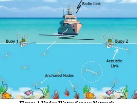
Underwater sensor networks have many applications in areas of environmental monitoring, disaster prevention, oil exploration and oceanographic data collection. These applications require high reliability and efficient communication. Packet delivery ratio, energy efficiency are the two factors considered for reliability in this work. Packet delivery is important for the applications as say timely warning of tsunami can safe many lives. Energy is important due to the difficulty in recharging or replacing batteries in most aquatic medium. Communication in under water wireless sensor networks is challenging because the acoustic links are subjected to high transmission power and high channel impairments. It results in higher error rates and temporary path losses. They deployment of underwater sensor networks is shown in the figure 1. Sensor nodes anchored at sea bed sense values and send via acoustic link to the collection center. underwater environment is difficult to retrieve the sensor nodes from the sea bottom.
The challenges in under water wireless sensor networks are Compared to Radio signals, acoustic signals perform well in under water communication. Propagation speed of acoustic links is less than the propagation speed using radio wave links because the characteristics of communication changes from the speed of light to the speed of sound. . Most of the terrestrial sensors nodes are static but the underwater sensor nodes can move due to different underwater activities, as during normal conditions a node can move 2-3 m/sec with water currents. The replacement of batteries for underwater
Revised Manuscript Received on November 05, 2019.
Asha M, Assistant professor, Dept. of ECE, GSSSIETW, and Ph.D research Scholar , VVCE, Mysuru. India,
T.P Surekha , Professor, Dept. of ECE, Vidya Vardhaka College of Engineering, Mysuru, India,
[image:1.595.306.546.259.440.2]communication is costly and also time consuming.Routing protocols must adopt a technique to reduce power consumption during the communication and minimum retransmission usage, in order to reduce the energy consumption. Data rate is low because of limited bandwidths. The data rates hardly exceed from 40 kb/s at a range of 1km.
Figure 1 Under Water Sensor Network .
In this work, a hybrid cross layer method is proposed to increase the reliability in under water sensor network. The hybrid protocol uses different mechanism at each lower layers of physical, data link and network. Transmission power control, aggregation, network coding, error correction methods, selective multipath routing are applied at each layer to achieve high packet delivery ratio with considerable energy consumption.
In [1] authors proposed an energy efficient routing schemes, which does not require location information. It achieved high packet delivery ratio for both static and mobile areas in dense or sparse networks. In [4] authors build model to evaluate the performance of routing protocols for the standard which are strobed preamble , simple asynchronous, receiver initiated , different network densities and traffic loads under the settings of duty cycle and designed. Duty cycle reduces energy consumption but delay is increased in this approach. The delivery ratio is also low in this approach. In [8] author suggested a novel geographic routing protocol which controls the network topology in underwater sensor networks, so that depth of the nodes can be adjusted for improving the connectivity of network , to forward data when the greedy geographic routing fail. Routing protocol depends highly on position of nodes which is not efficient for under water wireless
II. HYBRID CROSS LAYER SOLUTION The proposed hybrid cross layer solution is based on the concept of 2 Level clustering. The nodes are clustered based on the depth. The neighbor nodes who maintain relative position even in presence of movement till a depth level „d‟ from the surface of water are grouped as cluster. Among the cluster, the node which has lower relative motion to all the nodes is selected as Cluster head. The nodes in the depth level „0‟ to „d‟ are used for second level of clustering. These nodes are called super cluster heads. The cluster head nodes select the super cluster head near to it and communicate packets to super cluster head. Super cluster head relays packet to base station.
[image:2.595.319.536.68.271.2]The architecture of the solution is shown in figure 2.
Figure 2 Architecture
Each sensors node within a cluster is distributed with a random non conflicting duty cycle. By this way all nodes with in cluster are not active at all times. Energy is saved due to this duty cycling. Since at least a sensor node is available at any time for sensing, no events are missed. Each sensor node sends the event sensed to the cluster head node using DPSK modulation as in figure 2. The data from sensor node to cluster head is sent with error correcting codes(ECC) to restore the data in case of errors at cluster head without a need for retransmission. ECC can gives better bit error rate (BER) performance for the same or lower signal-to-noise ratio over a noisy channel compared to an uncoded system. For WSN having maximum energy efficiency in appropriate channel conditions, RS (Reed Solomon) code would be the best choice
The energy consumption is modeled using RS(n,k) for each node is as follows
n : code word length
k : Number of information symbols.
The energy consumed by the node is computed as Etotal = Eenc + ETX + ERX --- (1)
Etotal :Energy consumed by the network
ERX : Energy consumed by all nodes except first one during
the reception of data.
ETX : Energy consumed by all nodes during transmission.
Eenc : Energy consumed by the encoder at the first node.
Etotal in case of RS is
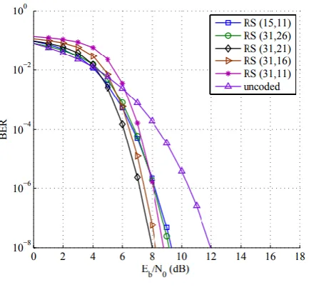
[image:2.595.54.280.254.411.2]--- (2) The BER is analyzed for different n,k value in RS and
Figure 3 BER for RS(n,k)
The Power consumption is measured for different k,n values in RS and is shown in the Table 1
Table 1Power Consumption
From this RS (31,26) gives satisfactory performance in terms of BER and has lower power consumption. So RS(31,26) is used for error correction from sensor node to cluster head. Cluster head broadcast the aggregated packets to nearby super cluster heads. Super cluster heads does network coding on the packets before transmitting to sink. More turbulence occurs at the layer from surface to depth „d‟, so redundancy is needed at these layers to compensate for the packet loss.
The super cluster head mix the packet from different cluster head and sends the composite packet to base station. At base station decoding is done to recover packets and redundant packets are dropped. A simple XOR based network coding is applied at super cluster heads , so as not to increase the number of packets and generate redundancy without any additional energy consumption. Data from two different cluster heads are XOR and sent to base station. At base station, all received packets are assembled and XOR is done to recover the original packets. Cluster head to super cluster head communication is transmission power controlled to reduce the energy consumption and avoid unnecessary networking coding that would result if the full transmission range was used by the cluster heads.
For super cluster head to sink communication, mobile sink is used in this work. One or more sink move at surface and stays for a brief period of time
broadcasts a hello message, so that super cluster can send the network coded packets to sink. The super cluster head to sink communication is made 1 hop to reduce the energy consumption. If it is static sink, the super cluster head to sink communication would have been as multi hop and energy consumption would have been more at super cluster head.
[image:3.595.307.546.49.243.2]Flowchart for the overall procedure is shown in Figure 4.
Figure 4Flowchart of Proposed Work
III.RESULTS AND DISCUSSIONS
[image:3.595.53.272.144.644.2]The proposed solution was simulated in Matlab. Simulation was conducted with following parameters
Table 2 Configuration Parameters
Parameters Values
Number of Nodes 50 to 250
Communication range 100m
Area of simulation 1000m*1000m
Node distribution Random distribution
Simulation time 30 minutes
Interface Queue Length 50
MAC 802.11
Number of Base station 1
Location of Base station Moving on surface
Initial energy of nodes 100 joules
Node movement 2-5 m around a center
point
The proposed work is compared against [1] and [4]. The performance is measured for the following parameters.
1. Delivery ratio of packet. 2. Network overhead. 3. Life time of a node.
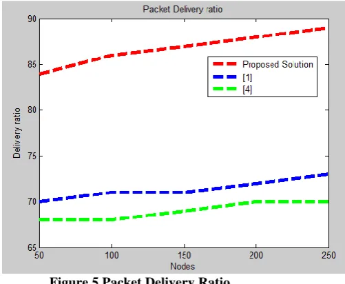
The packet delivery ratio is measured for different number of nodes in all three solutions and plotted below. Packet delivery ratio is measured by sensor nodes at level below d send packet at Constant Bit Rate of 5 packets per seconds and the delivery ratio is measured at the sink. From the results, the packet delivery ratio is higher in present work compared to [1] and [4] and the plotted graph is shown in figure 5.
Figure 5 Packet Delivery Ratio
[image:3.595.304.555.433.639.2] [image:3.595.49.288.710.779.2]Figure 6 Network Overhead
[image:4.595.49.289.49.245.2]Life time is measured as the time at which first node energy reduces to zero. Life time is measured for different size of network and plotted in figure 7 and shows that life time is higher in proposed solution compared to [1] and [4].
Figure 7 Life time
Figure 8 Packet Delivery Ratio vs Speed
packet delivery ratio is measured for various speed of sensors and the result is plotted in figure 8 and concluded that packet delivery ratio is high in the proposed work for variety of speed of nodes compared to [1] and [4].
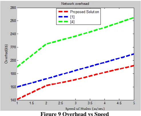
Figure 9 Overhead vs Speed
The network overhead is measured for different speed of sensors and the result is plotted in figure 9 and shows that ), the network overhead increases as the speed increases ,but the increase is lower in case of present work when compared to [1] and [4].
IV.CONCLUSION
In this work, a hybrid cross layer solution was proposed to ensure high packet delivery ratio with low energy consumption. The proposed work performed better than existing works with respect to the packet delivery ratio, life time and overhead of network. Due to use of network coding and error correction, retransmissions are avoided in the network. Due to multipath transmission, the packet delivery ratio is higher. Duty cycling and transmission power adjustment resulted in less energy consumption and increased the life time in the proposed work.
REFERENCES
1. Manal Al-Bzoor,et.al, “Adaptive power controlled routing for
underwater sensor networks” ,in Proceedings of the 7th International Conference on Wireless Algorithms, Systems, and Applications , pp 549—560.
2. Prasad Anjangi et.al , “Scheduling algorithm with transmission power
control for random underwater acoustic networks”,in Proceedings of OCEANS 2015—Genova, pp 1-8.
3. Weigang Bai , et.al, “Link scheduling method for underwater acoustic
sensor networks based on correlation matrix” , IEEE Sensors Journal 16,11, pp 4015-4022.
4. Rodolfo W.L, et. al, ” Modeling and Analysis of Opportunistic
Routing in Low Duty-Cycle Underwater Sensor Networks” ,Proceedings of the 18th ACM International Conference on Modeling, Analysis and Simulation of Wireless and Mobile,systems, November 02-06, 2015, Cancun, Mexico
5. Rodolfo W. L, et.al, “ Local maximum routing recovery in
underwater sensor networks: Performance and trade-offs”, in Proceedings of the IEEE 22nd International Symposium on
Modelling, Analysis, and Simulation of Computer and
Telecommunication Systems.
6. Rodolfo W. L. et.al, “ EnOR: Energy balancing routing protocol for
underwater sensor networks”, in Proceedings of the IEEE International Conference on Communications , pp 3293--3298.
7. Rodolfo W. L, et.al, “GEDAR: Geographic and opportunistic routing
[image:4.595.57.285.304.678.2]8. Rodolfo W. L,et.al , “ DCR: Depth-controlled routing protocol for underwater sensor networks” ,in Proceedings of the IEEE Symposium on Computers and Communications , pp 453--458.
9. Fatemeh Fazel, “ Random access compressed sensing for
energy-efficient underwater sensor networks”, IEEE Journal on Selected Areas in Communications 29, 8, pp 1660—1670
10. Leandro Villas, et.al ,”DRINA: A Lightweight and Reliable Routing:
Approach for in-Network Aggregation in wireless sensor networks” , IEEE Transactions on Computers, v.62 n.4, pp.676-689, April 2013
11. M. Sammer Srouji ,”A Reliable Erasure-Coding Based Data Transfer
Scheme for Wireless Sensor Networks” , proceedings of IEEE 17th
International Conference on Parallel and Distributed Systems, 481-488, December 07-09, 2011.
12. W. Lou and Y. Kwon., “H-SPREAD: A hybrid multipath scheme for
secure and reliable data collection in wireless sensor networks”, IEEE Transactions on Vehicular Technology 55, 4, pp 1320-1330. 13. Roee Diamant, et.al , "Robust spatial reuse scheduling in underwater
acoustic communication networks", Oceanic Engineering IEEE
Journal of, vol. 39, no. 1, pp. 32-46, 2014
14. Said Lmai, et.al ,"Tdma-based mac transmission schedules in
multihop grid ad hoc underwater acoustic networks", Underwater
Communications and Networking , pp. 1-5,2014.
AUTHORS PROFILE
Obtained B.E and M.Tech degrees from VTU, Belgaum and Persuing Ph.D in the field of Wireless Communication under the supervision of Dr.T P Surekha, Professor, Electronics and communication engineering department, VVCE.
Awarded Bachelor of Engineering from the university of Mangalore, M.Tech from VTU, Belgaum . Obtained her Ph.D degree in the department of Electronics and Communication engineering by VTU, Karnataka, , India. Her interest in research areas are Power system
communication studies, Modeling &