Retrospective Theses and Dissertations Iowa State University Capstones, Theses and Dissertations
1-1-1981
Clinical engineering projects : a comparison of
semiconductor temperature transducers and an
electrical safety study
Ralph W. Schilling
Iowa State University
Follow this and additional works at:https://lib.dr.iastate.edu/rtd
This Thesis is brought to you for free and open access by the Iowa State University Capstones, Theses and Dissertations at Iowa State University Digital Repository. It has been accepted for inclusion in Retrospective Theses and Dissertations by an authorized administrator of Iowa State University Digital Repository. For more information, please [email protected].
Recommended Citation
Schilling, Ralph W., "Clinical engineering projects : a comparison of semiconductor temperature transducers and an electrical safety study" (1981).Retrospective Theses and Dissertations. 18631.
temperature' transducers and an ele,ctrical safety study
:rs
u..
I q 11 I Sc Ii 33
c.' 3
by
Ralph W. Schilling
A Thesis Submitted to the
Graduate Faculty in Partial Ful"fillment of the Requirements for the Degree of
MASTER OF SCIENCE
Major: Biomedical Engineering
Signatures have been redacted for privacy
Iowa State University Ames, Iowa
1981
ii
TABLE OF CONTENTS
INTRODUCTION
TEMPERATURE SENSORS
Temperature Sensing Techniques Diodes
Transistors
Resistance thermometers Thermistors
Thermocouples
Procedure for Testing the Temperature Sensors Physical desc~iption of sensors
Test apparatus
Manner in which sensors were secured during testing Test circuits and calibration (where required) Actual testing
Transducer Operating Principles; Experimental Results; Discussion
Analog Devices AD590
National Semiconductor LX5700 Precision Monolithics REF-02 National Semiconductor LM335 · Motorola MTS102
Results· ELECTRICAL SAFETY STUDY
Effect of Electrical Shock
Electrical Shock - Microshock and Macroshock
,.
Possible Means of Eliminating Electrical Shock Hazards Electrical Safety Standards ,
Materials Used for Testing and Test Procedures Outlet Testing
Appliance Testing
Page l 3 3 3 9 13 16 18 20 20 22 23 24 30 30 30 34 37 39 41 45
48 .
Results
LITERATURE CITED · ACKNOWLEDGMENTS
APPENDIX A: DATA OBTAINED FROM TESTING THE FIVE TEMPERATURE TRANSDUCERS
APPENDIX B: DATA SHEETS USED FOR THE CARE CENTER ELECTRICAL SAFETY TEST
APPENDIX C: REPORT TO CARE CENTER ADMINISTRATOR
Page
58 60 64
65
1
INTRODUCTION
Clinical engineering is rapidly becoming a recognized field of engi-neering and the need for the services of the clinical engineer is becoming more apparent to health care facilities. The services of the clinical engineer include supervision of electronic technicians in repair and maintenance of equipment, setting up electrical safety proqrams and ad-vising the medical staff on the purchase of equipment. It is up to the clinical engineer to provide responsible service to the patient and health care professionals as to their use of, and contact with, biomedical equip-ment. The clinical engineer must be trained in areas ranging from
electrical engineering to physiology because of the many areas in which he must function.
This thesis consists of two projects, both of which are typical exam-ples of what a clinical engineer might be asked to do. One is the com-pari·son of semi conductor temperature transducers. The either is an el ec-tri cal safety study at a local nursing home.
Five semiconductor temperature transducers were tested to see if they met manufacturers.' specifications and to gain some familiarity with tem-perature measurement. Diode thermometers, transistor thermometers, re-sistance thermometers, thermistors, thermocouples and the five semicon-ductor temperature transducers are discussed.
The Celsius temperature scale was used, where possible, for ease of com-parison and understanding.
In the modern health care facility, it is possible to find a patient connected to as many as 8 to 10 different pieces of electronic equipment. This increase in the use of electronics provides better health care, but introduces the hazard of electric shock. It is the responsibility of the clinical engineer to provide an electrically safe environment for the patient. Training of the operators of medical equipment and ·device test-ing are important parts of this responsibility.
3
TEMPERATURE SENSORS
Temperature Sensing Techniques
Diodes
Voltage varies with temperature across a forward conducting p-n junction (McNamara, 1962). The.diodes tested over the -40°C to +90°C range included 1N270, 1N56A, 1N38AG, 1N457, 1N459, and FD300. This group included both silicon and germanium, and both glass and plastic encapsu-lated diodes. Voltage versus temperature was plotted. The Ge diodes had a mean slope of -1.83±0.07 mVl°C and the Si diodes had a mean slope of
-2. ll±0.06 mV/°C. These values were found to agree well with results
found by other workers.
Table l contains a comparison of characteristics of temperature transducers (Ri ezenman, 1974). The silicon temperature transducer
column was modified. A list of manufacturers of solid state temperature sensors, thermistors, thermocouples and RTDs is available on request from Instruments and Control Systems Journal (Hall, 1979).
Resistance-temperature Si 1 icon temperature
Parameter Thermistor device Thermocouple transducer
Sensitivityf°C Linearity.
-4% +0.4% +60 µV +200 nV to +100 mV
Highly exponential Very linear Somewhat nonlinear Very linear Room temperature
resistance range
available SQ to 20 ·M.Q
Minimum temperature -185°C Maximum temperature 300°C
Minimum size 0.13 mni· dia beads
Room temperature error Typically ±20%
Cost $5
lOQtolKn NA
-185°C -185°C
750°C 3000°c
l.5x3x30 mm Small wire
±0.25°C About 2°C
$25 $2
NA -100°c +150°C
IC chip-miniature ceramic package O. l°C to 8°C $1 to $30
5
depends on the current used and the type of diode. For a given diode, good repeatability in voltage vs. temperature was observed.
Silicon diodes as temperature sensors have the advantage of high linearity and low 1;ime constant (Anonymous, 1975). The temperature sensing circuit.described in ·this paper can be used from -50°C to 200°C. The diode voltage must be measured precisely, so a stabl.e reference source was needed. A 723 IC voltage regulator was used to obtain a stable power source for the diode and the rest of the circuitry. A constant .current was supplied to the 1N4l48 sensing diode. This arranagement is necessary because the diode is, in effect, a voltage source with a finite internal resistance, and any variation in the current flowing through it would therefore produce a change in the voltage which would be incorrectly in-terpreted as a change in temperature. It is necessary to calibrate this circuit for proper operation. The output of this thermometer circuit was a temperature dependent voltage, which was read with a voltmeter.
A 1N914 temperature sensing diode was used to convert temperature to a numerically equivalent frequency for direct display or for instrumenta-tion (Williams and Ourgavich, 1975). The circuit provided O. l°C resolu-tion from 0°C to l00°C with an accuracy of ±0.3°C. A l
mA
current.was sent through the temperature sensing diode. A 2N2222 transistor and its associated components provided an output pulse that was compatible with transistor-transistor logic. While in operation, the circuit functioned as a voltage-to-frequency converter. A LM301A op amp was used, and the only variable voltage available to it was the temperature-dependent -2.2 mV/°C potential from the sensing diode ... The calibration procedure must beI
repeated two or three times until the adjustments cease to interact. Once the circuit is adjusted, its. output frequency is 10 times the sensed tem-perature. For· example, if the temperature is 27.5°C, the meter will read 275 Hertz. The output frequency can be counted by TTL counters.
A remote temperature sensing probe was built using four 1N914 diodes in series as the temperature sensing element (Elmore, 1976). The probe sensed temperature by the change in voltage drop across the four forward-biased silicon diodes .. As the temperature increased, the voltage across the sensing diodes decreased at the rate of -2 mV/°C for each diode in the probe. A zener diode and transistor regulated the voltage to the probe so that voltage readings were relatively independent of battery voltage
fluctuations ..
A simple temperature-to-voltage converter was made, based on the 741 op amp (Turner, 1977). It used a minimum of components and despite its simplicity, it was capable of producing an output voltage proportional to temperature over the range -20°C to 120°C. The circuit described in this paper used a· diode as the temperature sensing element and its voltage varied linearly with temperature if it was driven by a constant current. Once the zero control was set, the diode current was fixed. The output voltage could be set to zero at any desired temperature, so calibration in either degrees Centigrade or Fahrenheit was very simple. The output
7
A low power LM324 quad op ·amp and a diode probe were the central elements of an electronic thermometer (Nezer, 1977). An op-amp in con-junction with an LM113 reference diode, produced a constant 1.5 V output which was vi.rtually independent of variations in battery voltage. This supplied the sensing diode with a constant current of about 0.5 mA. A simple calibration procedure must be performed for proper operation. If a wide range of temperatures (0°C to 150°C) is to be measured, a transistor diode (base and collector connected) is often preferable to a diode, be-cause its properties better approximate an ideal p-n junction. But in applications where temperature variations are small, a glass encapsulated diode is more convenient (Nezer, 1977). This glass encapsulated diode. thermometer is sensitive enough for medical applications where there are small temperature variations. When stray capacitances are minimized at the probe, precision is better than O.l°C.
A diode sensor and an analog-to-digital converter were used to build a thermometer which measured temperature di gi tally (Hurzburg and Hadley, 1978). No buffers or op amps were used, so that temperature drift errors associated with amplifiers were eliminated. Unlike its analog counter-part, the circuit described in this paper remained calibrated over a wide temperature range from -199° to +100° in either the Celsius or Fahrenheit scales. The 3 1/2 digit A-D converter limits the circuit resolution to O. l°C. An MC14433 converter chip changed th.e output voltage of the 1N4148 silicon temperature sensor diode into a binary-coded-decimal number. An MPSA20 transistor and associated network operated the sensing diode. This circuit must be calibrated to read the proper temperature on the display .
An MC14511 BCD-to-seven-segment decoder driver and an MC1413 hexadecimal inverter were used to display the BCD-number on an HP5082 display. The error of the system was limited to no .greater than l.0°C through the use of a standard diode sensor. Diode sensors with an error of less than 0.6°C are available on a special order basis from Motorola.
An empirical approach rather than the constant current principle of diodes was used by Treharne and Riley (1978) in order to extend the linear range to ±200°C. A forward biased DA1703 diode was the sensor. Some other components of the system included an RCA CA3085 op amp, re-sistor network for calibration and a DVM for readout. The relationship they obtained was·
v
0=
m(Tc ± 0.5 mV)where
v
0 is the output voltage and the slope, m, was chosen to be l mV/"C. Thus, any 3 1/2 digit ±200 mV digital voltmeter could be used. Tc is the measured temperature in•c.
The calibration procedure and circuit design allow for easy interchangeability of the sensing diode with a maximum un-certainty no greater than ±0.5°C.:•.
9
temperature differential exceeded a threshold, it was sensed by an op amp configured as a ·comparator. This arrangement caused the output to go from low to high.
Transistors
A transistor with its base and collector connected is often preferable to a diode. because its properties better approximate an ideal p-n junction
( Nezer, 1977).
A low-le.akage CIL511 silicon .planar transistor was used as a tempera-ture sensor (Supe, Patil and Agarwal, 1969). The emitter current, IE, of a transistor operated at a constant VBC is given.by.
-q(Eg - VBE) IE = Ae kT
where A
=
a constant for the transistor material q=
the electron chargek
=
Boltzmann constant T=
temperature in °KEg = ionization potential corresponding to the forbidden energy gap
of the transistor material VBE
=
base-emitter voltage V8c
= base-collector voltageRearranging,
then
I
VBE
=
Eg +~T
l n (ll
This equation indicates that if VBC and IE are held constant, VBE is
linearly dependent on temperature. For silicon, this linear dependence is valid over the temperature range of -60°C to +l50°C.
The CIL5ll transistor was operated at a constant emitter current of 0.1 mA. The sensor output was compared to a reference and the difference was fed to a low-drift differential amplifier. This output was connected
to a voltmeter. After calibration, readings were taken in the 20°C to 100°C temperature range. No hysteresis was observed.
An OC200 silicon sensing· transistor was used in a circuit measuring temperature in the range. -80°C to +150°C (Pallett, 1963). The principle used was that of constant current biasing with respect to the base-emitter voltage.
The sensing transistor formed the first stage of a de amplifier and the. voltage VBE was derived from a voltage divider across the output of the amplifier. The results were linear to within 1% over the range ±l00°C. The transistor of the temperature measuring probe. could be interchanged with one of·the sa~e type.
11
provided some amplification of its own. After calibration, the output was accurate enough so that it did not vary more than 0.05°C.
A digital thermom~ter using a low-cost transistor sensor was de-signed, built and tested (Box and Neil, 1976). The principle used was that of constant current biasing with respect to the base-emi.tter voltage. The collector and emitter of. the BC109C sensing transistor was connected as one arm of a bridge circuit. When the temperature of the sensor in-creased, its internal impedance decreased and its current increased up-setting the balance point of the bridge. Balance was returned by de-creasing VBE to return Ic to its preset level. This was achieved by ro-tating the wiper of a potentiometer calibrated in °C. The bridge balance was sensed with a comparator and two light-emitting diodes. This instru-ment had a range of 0°C to 100°C and a resolution better than 0.05°C. A three-digit dial with one-tenth increments on the last digit was fixed to the balance potentiometer and provided a digital readout. The instrument could be converted to operate over any range between the limits of -100°c and +180°C.
Three 2N706A transistors were used as sensors for temperature moni-toring and control in a central heating system (Thomas, 1977). The rela-tionship of VBE varying linearly with temperature for a constant collector. current was used. The transistors monitored the room temperature, boiler temperature and outside temperature and their outputs were summed with a 741 op amp. ·
fact that if emitter current is held constant,
v
8E becomes a linear func-tion of temperature. This circuit had a highly linear output which was adjustable from 1 O mV/°C to 360 mV/°C. The 1 i neari ty of the circuit was typically within ±0.05%.Silicon diodes such as the FD200 have been used as temperature sensors. Pease (1972) found a temperature coefficient of approximately -2 mV/°C. This diode was used in an op amp circuit, where the amplifier functioned as a follower with positive gain. The output sensitivity was +100 mV/°C, providing a full-scale range of ±10 V for the ±l00°C tempera-ture range. A problem with this circuit was that the reference voltage must be stable since a ·50 mV shift in the supply would cause a l°C appar-ent change at the output. An alternative circuit was designed, which
used silicon planar transistors such as 2N930, 2Nl6l3 or 2N3903 as the
temperature sensing elements (Pease, 1972). l~ith the modified circuit,
li.nearity was typically within O.Ol°C over a 0°C to 20°C range and better than O.l°C from -50°C to +100°C.
Two different temperature sensing circuits were designed and bui 1t by
13
Two adjustments were necessary for calibration, and since they were inter-dependent, they must be repeated two or three times. For the diode cir-cuit, a Fairchild FD300 diode was the sensor, and two.Fairchild uA748 op amps were also used. The· first op amp was a constant current source for the sensing diode. Since most temperature measurements are made in the 0°C to 100°C temperature range, the second op amp was used to choose what-ever temperature range was desired. Compared to the transistor circuit, the diode circuit was a little harder to fabricate and shield effectively. The diode had two advantages though. It had a simple calibration proce-· dure and was about half as sensitive to reference voltage changesproce-· as the
transistor sensor circuit. Resistance thermometers
In the literature, resistance thermometers also go by the name re-sistance temperature detectors or devices (RTDs). In these devices, very pure wire is wound in a coil to serve as the sensing element (Fluke Manu-facturing, Inc., 1974). Resistance changes are monitored using various bridge circuits to provide temperature data as a direct function of cur-rent flow. RTDs are perhaps the most accurate and linear temperature sensors available over a wide temperature range and are therefore often used as laboratory standards. The signal from an RTD is ·simply a change in resistance.
(Sandford, 1976). Wheri unusually high accuracy is required, the RTD can be combined with a device to produce a linearized output voltage.
The choice of metal depends on several factors; the most important being the ease .of obtaining a pure metal, and the capability of drawing it into a fine wire. Also, it must have a repeatable temperature coeffi~ cient, be linear, and have a relatively high rate of resistance change. At present, five .metals are commonly used: platinum, tungsten, copper, nickel and the alloy Balco. Rhodium, iridium, silver, iron, and
tantalum are occasionally .used. Platinum is the most widely used and nick el and copper are the second choices.
Platinum has a high melting point, resists oxidation and is chemi-cally stable. It can be contaminated by gases in a reducing atmosphere and can act as a catalyst when certain hydrocarbons are present. There-· fore, good platinum sensors are usually encapsulated. Nickel also is available in nearly pure form. It has the highest resistance change of any metal between 0°C and· l00°C. The sensitivity decreases sharply above 285°C and the resistance change is quite nonlinear. Copper oxidizes rapidly and loses its purity, which makes it less desirable than the others. However, it is easy to refine and draw into uni form wire and it absorbs heat uniformly.
15
, B
Platinum Sensor
Figure 1. Typical circuit arrangement for a platinum RTD (Sanford, 1976)
Knowing the resistance of the RTD and the temperature coefficient, the temperature can be determined from tables of resistance vs. tempera-ture. There are two commonly used temperature coefficients. A coeffi-cient of 0.003916 ohm/ohm/°C is referred to as an SAMA curve and is gen-erally used in the United States. A second coefficient, 0.00385 is re-ferred to as the DIN 43760 curve and is the International and.European Standard (Hall, 1978). The two curves are not interchangeable. Minco Products, Inc., Minneapolis, Minnesota points out that manufacturers of platinum RTDs have not standardized resistance-temperature relationships (Sandford, 1976). As a result, serious errors can occur from intermixing RTDs from several suppliers.
[image:19.570.136.371.54.345.2]and RTDs can .be very small in size. Sometimes RTDs can be fragile, ex-pensive and difficult to mount.
A recent development in platinum resistance thermometry is based on the refinement of film deposition techniques combined with automated methods of trimming. This has led to a new generation of small flat.de-tectors with the temperature precision measuring capability of wire-wound devices (Walko, 1976). These detectors are less expensive than the de-vices which use platinum wire. These new dede-vices also are called thin film detectors. The sensors are at least the equal, technically, of the existing wire products. Also, because of their smaller size, there is a greater variety of possible app1 i cations for temperature measurement by platinum resistance thermometry. Detectors manufactured by Rosemount Engineering, England are called Platfilm. They are 3 mm wide, 30 mm long and 1.5 mm thick. They operate in the range -50°C to 500°C and have a metal sheath. Pl atfi lm al so is packed into a cyl i ndri cal ceramic sheath and is 4 mm in diameter and 32 mm long. Another company which should presently be manufacturing such a detector is. Heraens (England), which has a· glass encapsulated platinum layer on a ceramic substrate. These are called Thin Film Detectors. Matthey (England) also produces thin film detectors, as robust replacements for thermocouples and platinum resist-ance detectors. These are called Thermafilm detectors. Some of these thin film detectors are made with resistances of 100±0. l n.
Thermi stars
17
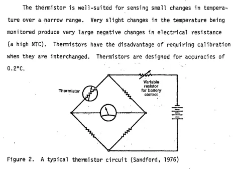
oxides of metals such as nickel, iron, and titanium. In temperature sensing, they are usually one leg of a Wheatstone bridge circuit,. as seen in. Figure 2. Their resistance is a direct function of absolute tempera-ture, decreasing as temperatur.e increases. Most thermistors have a nega-tive temperature coefficient, but some have a posinega-tive one. The
thermistor has an exponential curve for its resistance versus temperature transfer function. At very low temperatures, most thermistors approach i nfi ni te resistance, and conversely, at high temperatures, very low re-sistance. Interchangeability is still somewhat of a problem, but low cost is an asset. Thermistors that initially have certain resistance values at a given temperature. will sometimes vary widely from that value after pro-longed use (Mangum, ]g77).
The thermistor is well-suited for sensing sma 11 changes in tempera-ture over a narrow range. Very slight changes in the temperatempera-ture being moni tared produce very large negative changes in electrical resistance
(a high NTC). Thermistors have the disadvantage of requiring calibration when they are interchanged. Thermistors are designed for accuracies of 0. 2°C.
Thermistor
Variable
resistor
for battery
control .
Figure 2. A typical thermistor circuit (Sandford, 1976)
[image:21.572.42.508.372.710.2]A typical application of thermistors is to compensate temperature in electrical circuits. Since most electrical conductors have a positive electrical resistance· change, the NTC thermistor in the same circuit compensates in the opposite direction. The result is to hold circuit re-sistance constant over a wide temperature range.
Thermistors are rugged and provide a relatively high degree of sta-bility over a long life span (Hall, 1978). They are available with re-sistances of O.fr n to 80 Mn. Standard forms include discs, washers,· rods, beads and probes. The thermistors' relatively large resistance change per degree change in temperature provides good accuracy and resolution. A typical 2000 n thermistor with a temperature coefficient of 3.9%/°C at 25°C will have a resistance change of 78 n/°C compared to only 7.2 n for a platinum resistance bulb with the same basic resistance.
A typical th.ermistor bridge does not require amplification. The voltage output of the typical thermistor bridge at 25°C will be 18 mV/°C with a 4000 n thermistor.
Therl1locoupl es
A thermocouple is a junction between two dissimilar metals at which a voltage develops when exposed to heat. To obtain useful data, two junc-tions must be used. in a thermocouple circuit. The sensing junction that produces a signal proportional to the sensed variable is connected to a reference junction maintained at a specific temperature. The resultant· output of both junctions is then directly related to temperature.
19
a .critical cost factor since most thermocouples use fairly expensive metals for wire. Copper extensions can be used in many cases, without s i gni fi cant 1 oss of accuracy. A thermocouple si gna 1 requires circuitry to amplify its 20-70 µvolt/°C signal..
Thermocouples provide moderate accuracy, suitability over a broad temperature range, ruggedness, high reliability, low cost and great versa-tility of application. In practice, the temperature of the reference junction is held at a constant known value. The temperature of the meas-uring junction is determined accurately by measmeas-uring the circuit voltage and referring to calibration tables for the particular thermocouple mate-rialS. Since the voltage generated by a thermocouple circuit is a func-tion of the difference in temperature between the measuring juncfunc-tion and the reference junction:, it is important that the reference junction be maintained at a constant, known temperature. This can be accomplished with a temperature-controlled furnace, an ice bath or an electrical means of simulating a known temperature. Electrical temperature simulation is the most convenient and popular means of providing reference junction compensation.
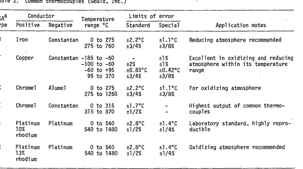
Although many materials can be combined to produce a thermoelectric effect, certain pairs have become more widely used than others. The National Bureau of Standards gives reference tables for the thermocouple material combinations that are most commonly used in the United States. Some common thermocouples are listed in Table 2.
Procedure for Testing the Temperature Sensors
Physical description of sensors
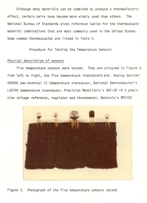
Five temperature sensors were tested. They are pictured in Figure 3. From left to right, the five temperature transducers are: Analog Devices1
AD590K two-terminal IC temperature transducer, National Semiconductor1s
LX5700 temperature transducer, Precision Monolithic1s REF-02 +5 V
preci-sion voltage reference, regulator and thermometer, Motorola1s MTS102
[image:24.557.31.514.71.737.2]Table 2. Common thermocouples (Gould, Inc.)
ISA a Conductor Temperature Limits of error
. type Positive Negative range °C Standard Special Application notes
J Iron Cons tan tan O to 275 ±2.2°C ±l.l°C Reducing atmosphere recommended 275 to 760 ±3/4% ±3/8%
T Copper Constantan ~185 to -60 ±1% Excellent in oxidizing and reducing
-100 to -60 ±2% ±1% atmosphere within its temperature -60 to +95 .±Q.83°C ±0.42°C range
95 to 370 ±3/4% ±3/8%
K Chromel Alumel 0 to 275 ±2.2°C ± l. l °C For oxidizing atmosphere 275 to 1260 ±3/4% ±3/8%
"'
E Chromel Constantan O to 315 ±l .7°C Highest output of common thermo- ~
315 to 870 ±1/2% couples
s
Platinum Platinum O to 540 ±2.8°C ±l.4°C Laboratory standard, highlyrepro-10% 540 to 1480 ±1/2% ±1/4% ducible
rhodium
R Platinum Platinum O to 540 ±2.8°C ±l.4°C Oxidizing atmosphere recommended
13% 540 to 1480 ±1/2% ±1/4%
rhodium
[image:25.783.95.710.60.404.2]silicon temperature sensor and National Semiconductor' s LM335H precision temperature sensor. The Analog Devices' AD590 was in a three-pin metal can package and the National Semiconductor LX5700 was in a four-pi n metal can package. The Precision Monolithic's REF-02 was in an eight-pin metal can package and the National Semiconductor LM335 was in a three-pin metal can package. The Motorola MTS102 is not manufactured with a metal can package--a three-pin plastic package is available.
Test apparatus
A photograph of the apparatus which was used to test the sensors is in Figure 4. From left to right is: the Hewlett-Packard Model 34768 digital multimeter, Analog Devices Model 904 ±15 V power supply, testing circuit, water bath, and Koldwave Products beverage dispenser. The sensors were secured in styrofoam cups which were placed in the water
[image:26.551.53.492.81.671.2]23
bath as shown in Figure 4. The Kold\'Jave Products beverage dispenser had a pumping mechanism and was used to cool the temperature of the water bath. A Thermomix 1440E Bronwill Constant Temperature Circulator and Fisher 1500A mercury thermometer can be seen in the water bath of Figure 4. The Thermomix unit was used to raise the temperature of the water bath. The
Fisher mercury thermometer was accurate at 0.1°C and was used to determine the actual temperature of the water bath.
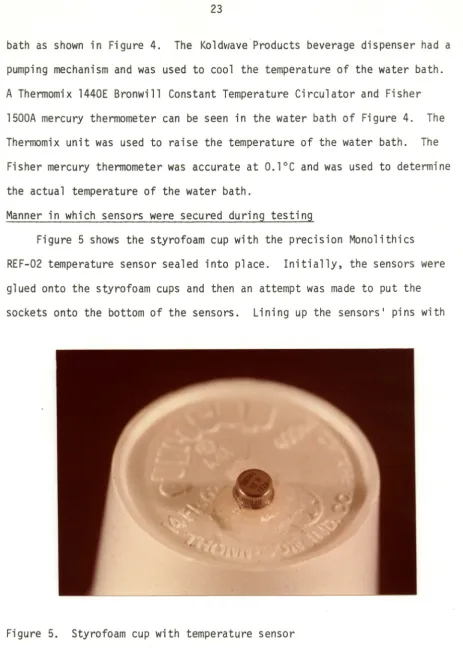
Manner in which sensors were secured during testing
Figure 5 shows the styrofoam cup with the precision Monolithics REF-02 temperature sensor sealed into place. Initially, the sensors were glued onto the styrofoam cups and then an attempt was made to put the sockets onto the bottom of the sensors. Lining up the sensors' pins with
[image:27.560.49.513.59.713.2]the socket holes proved to be extremely difficult. Changing the tech-nique of securing the temperature sensors proved to be more successful. First, .a circular, flat, one-inch diameter piece of styrofoam was cut from the bottom of a cup. Then, the sensor pins were pushed through this piece and the sensor was inserted into its socket. Then, a small hole was cut into the bottom of a new styrofoam cup, just large enough so the sensor could fit through. The waterproof sealer which was used to glue the sensor and flat tab of styrofoam into place was Dow Corning Silastic Medical Adhesive Silicone Type A. During curing, approximately 6.4% acetic acid is evolved, so it is preferable to do this in a ventilated area.
Test circuits and calibration (where required)
The circuit used for testing the Analog DevicesAD590 is diagrammed in Figure 6. VT' the output voltage is l mV/°K. When the AD590 was cali-brated at 50°C, the output was set equivalent to 273°K + 50°K or 323°K, which was 323 mV.
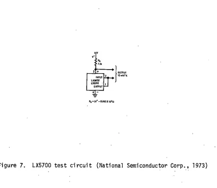
Figure 7 shows the circuit used to- test the National Semiconductor LX5700. The supply voltage was 15.17 V. To determine the value of Rs' the following equation was used:
Rs
=
(V+ - 6.8 V)x
103n
Rs = ( 15 . l 7 - 6. 8 V) x 103 nRs = 8370 n
A 1/4 W, 5% tolerance, 8200 n carbon resistor was used for R . The output s is 10 mV/°K.
I
i
. j
25
5V+
+
R
1oon
Figure 6. AD590 test circuit (Analog Devices Inc., 1977)
'"
,.
'· ""
R1 • w• -8.IY) lf 10"11
J '"'"'
10rnVfKFigure 7. LX5700 test circuit (National Semiconductor Corp., 1973)
I I
I
I
'
I
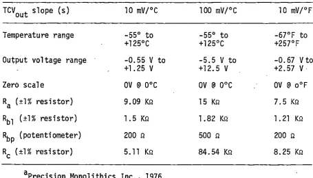
[image:29.574.72.520.41.775.2] [image:29.574.57.484.370.740.2]The circuit used for testing the Precision Monolithics REF-02 is shown in Figure 8. Table 3 provides the user with three possible output scales. Once the choice is made, the table provides resistor values for the test circuit. The scaling factor chosen was s
=
10 mV/°C.Ra was a 9.02 Kn, 1/2 W, IRC ±1% metal film resistor. Rbl consisted of two 0.75 Kn, 1/4 W, IRC ±1% metal film resistors in series. Rc was a 10.l Kn resistor in parallel with a 10.3 Kn resistor resulting in a 5.15 Kn resistance. These two were also 1/4 W IRC ±1% metal film resistors. RBP was a 200 n potentiometer.
l ith i cs OP-02.
The op amp used was a Precision
Mono-To test the REF-02, a calibration procedure had to be used. Step one consisted of measuring the ambient temperature, TA' in .0
c
and measuringVtemp· TA was 23.0°C and Vtemp was 641 mV. Step two consisted of calcu-lating the calibration ratio r.
_· Vtemp{in mV) r - s(TA + 273) r
=
10(23.0 641+ 273) r = 0.2166
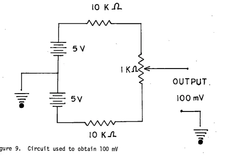
Step three consisted of turning off the power, shorting the VREF terminal to ground, and applying a precise 100 mV to the Vout terminal.
The precise 100 mV was obtained by using ·a dual 5 V power supply. 1 To obtain the precise 100 mV, the circuit of Figure 9 was used. A l Kn
1Model 500 dual power supply manufactured by Spar Electrostatics, San Diego, California.
REF«!
TRIM
""
'• ~•n
27
••
Figure 8. REF-02 test circuit (Precision Monolithics Inc., 1976)
10 K
Jl.
5V
-
i
5V
10 K.lt
Figure 9. Circuit used to obtain 100 mV
OUTPUT.
[image:31.569.175.384.107.278.2] [image:31.569.66.506.394.703.2]Table 3. ·Resistor values for the REF-02 test circuita
TCVout slope (s) 10 mV/°C 100 mV/°C 10 mV/°F
Temperature range -55° to -55° to -67°F to
+125°c +125°C +257°F
Ou~put voltage range -0.55
v
to -5.5 V to -0.67 Vto+1.25
v
+12.5v
+2. 57v.
Zero scale
ov
@ 0°cov
@ 0°C OV @ o°FRa (±1% resistor) 9.09 Kri 15 Kri 7.5 K!l
Rbl (±1% resistor) 1.5 Kri 1. 82 K!l l . 21 Kil
Rbp (potentiometer) 200 !l 500 !l 200 !l
RC (±1% resistor) 5.11 K!l 84. 54 Kri 8.25 K!l
aPrecision Monolithics Inc., 1976.
potentiometer and two 10 Kri resistors were used. A voltmeter was used to check the output, and the potentiometer was adjusted so that 100 mV was obtained.
After the 100 mV was applied to the output terminal bf the test
.cir-cuit, step four of the calibrating procedure was performed. In step four, Rbp is adjusted so that:
VB= r(lOO mV) = (0.2166)(100 mV) = 21.66 mV
[image:32.569.52.508.109.369.2]29
Step five included turning the power on and adjusting RP so that Vout equaled the correct value at ambient temperature. RP was adjusted so that
V0 was equal to 230 mV at 23°C. Calibration for the REF-02 was then complete.
Figure l 0 shows the test circuit used with the f'ati ona l Semi conductor LM335. R1 is a 10.l Kn resistor. It is a 1/4 W Dale metal film precision (1%) resistor. V was chosen to be a 12 V power supply. The LM335 has + less than l n dynamic impedance. Since the Hewlett-Packard digital volt-meter has a very slight loading effect and the LM335 operates between 400 µA and 5
mA,
the values for R1 andv+
put the LM335 in its operating range. The output is 10 mVI° K.Figure il shows the test circuit used with the Motorola MTS102. A 12 V power supply was used. To make up the 110 Kn, two resistors .were used in series. These were 100 Kn and 10 Kn and both resistors were 1/4 W Dale 1% tolerance metal film resistors.
OUTPUT
!Om
V/
0I<
LM335
Figure 10. LM335 test circuit (National Semicondu.ctor Corp., 1973)
[image:33.571.103.481.442.673.2]Figure 11. Test circuit for MTS102
Actual testing
All of the temperature sensors were tested three times from S0°C to 0°C at S°C intervals. These three test runs were averaged. Also, all of the temperature sensors were tested for hysteresis effect by testing them from 0°C to S0°C at S°C intervals. A Fisher lSOOA mercury thermometer accurate to 0.1°C was used as the standard.
Transducer Operating Pri nci pl es; Experimental Results; Discussion
Analog Devices ·ADS90
The Analog Devices ADS90 is an IC temperature transducer with an operating range of -12S°C to +200°C. Analog Devices guarantees the ADS90K for a -SS°C to +1S0°C range. Overall absolute accuracies of ±O.S°C have been obtained over that temperature range.
I
I
' '
. :
[image:34.571.50.514.45.406.2]I
I·
31
The AD590, which ·is fabricated using laser trimmed thin~film-on
silicon technology, is a calibrated temperature-dependent current source. For 5upply voltages between -14 V and +30 V, the device acts as a constant-current regulator, passing l µA!° C.
In the circuit schematic seen in Figure 12,
o
9,0
10, and Oll are the critical temperature sensing transistors. These are located at the oppo-site end of the chip from the main power-consuming componentso
1,0
2,o
3,0
4,0
7 and0
8. The temperature sensing principle used is that if twoidentical transi·stors are operated at a constant ratio of collector cur-rent densities,
rc
1;rc
2, then the difference in their base;..emittervoltages (LIV8E) will be (kT/q) ln (Ic1/Ic2). Since k and q are constants, the resulting voltage is directly proportional to absolute temperature , (PTAT). The PTAT voltage is converted to a PTAT current by low-tempera-ture-coefficient thin-film resistors. The total current of the device is
+
R1 Rz
zson 104on
"•
"' nkn
"'"
"'
On"•
"'"
[image:35.571.60.549.162.716.2]then forced to be a multiple of the PTAT current. Transistors Q9 and Q11
produce the PTAT voltage. Rs and R6, which are laser trimmed on the wafer to ca 1 ibrate the devfce at 2S° C, a re a 1 so used to convert the vo 1 tage to current. Q10 supplies all the bias for the rest of the circuit, forcing
the total current to be PTAT. Figure 13 shows a typical V-I character-istic of the circuit at +1S0°C, +2S°C, and -SS°C. At 2S°C, power require-ment for the ADS90 operating at S V is l .S mlo/ (Analog Devices Inc., 1977).
As tested, the ADS90 had excellent results, as can be seen in
Appendix A and Figure 14. There was no hysteresis effect and it was well within the claimed ±l.0°C absolute error with +2S°C calibration. There was no slope error. It also was within the ±O.S°C claimed nonlinearity.
Referring to Table 4, it can be seen that the ADS90 had a 1 east squares linear regression coefficient of 1.00000. Appendix A contains the data of
423
lout
(µAJ 298
218
+150°C
I-+25°C
r--55°C
f-L...<~11L.-Ll2~~3~4'-~5'--~6--tj3~V
[image:36.571.102.470.430.666.2]SUPPLY VOLTAGE
0.33
0.3
0.31 Output Voltage
0.30 V0 in Volts
0.29
0.28
0 5
33
10 15 20 25 30 35 40
Mercury Thermometer Temperature in °C
Figure 14. Plot of temperature vs. output voltage for the AD590
[image:37.569.55.504.103.661.2]the five temperature sensors. The first column shows the temperature, as read from the standard (the mercury thermometer). The next three columns are the three test runs, and the average column is a mathematical average of the three test runs. The last column is the temperature determined by the sensor, as calculated from the output voltage.
Because the AD590 is a current source with only two active leads, the sensor is virtually free from noise pick up even when remoted over
hundreds of feet of cable (Owen, 1978). The AD590 should presently be available in a miniature ceramic packaged version, which, if it were a biocompatible ceramic, would make the AD590 an excellent temperature sensing device for implantation.
National Semiconductor LX5700
The LX5700 temperature transducers are accurate over the -55°C to +125°C temperature range. Figure 15 shows the block diagram of the LX5700. The LX5700 exploits the temperature sensitivity of the
emitter-ACTIVE ZE•ER
8.IV OUTI'UT ID111Vr1C.
-.
,-Figure 15. Block diagram of the LX5700 (National Semiconductor Corp., 1973)
I
. I
[image:38.570.53.536.285.736.2]35
base voltage. It uses a pair of matched transistors operating at differ-ent collector currdiffer-ents. The difference in their base-emitter voltages is proportional to the absolute temperature of the transistors and to the natural logarithm of the ratio of their collector currents.
The 6.8 V active zener diode of Figure 15 provides a stable voltage reference for the thermal sensing circuit and for the input stages of.the amplifier and it also provides a 6.8 V reference between leads 3 and 4,
available for externar use. As tested, leads 1 and 2 were connected, which makes the operational amplifier a unity-gain voltage follower.
When the op amp is connected as a comparator, the output will switch as the temperature crosses the set point making the device useful as an on-off temperature controller. The output collector can be brought back to a voltage higher than 6.8 V allowing the LX5700 to drive lamps and relays.
A low cost digital thermometer using the LX5700 IC and a digital panel meter kit was designed and constructed (Swift, 1979). The thermome-ter's resolutionwas 0.1°C and total parts cost was less than $55. The ·LX5700 temperature sensors are not interchangeable, unless tne thermometer
is recalibrated. A simple electronic thermometer having accuracy and resolution better than l°C was designed and built by Box, 1974.
3.3
3. 1 Output Voltage
3.0 V0 in
i
Vo its I
2.9
2.8
0 5 10 15 20 25 30 35 40 45 50
Mercury Thermometer Temperature in °C
[image:40.572.58.554.54.673.2]37
slope error (in perce~t)
=
[(10 mV/°C - 9.8 mV/°C)/(lO mV/°C)] x 100=
2%. At 1.0mA
·operating current, the LX5700 has a 7.0 mW power dissipation. Precision Monolithics REF-02A simplified schematic of the REF-02 circuit is shown in Figure 17. The REF-02 offers the versatfl ity of being able to choose a temperature scale, such as 10 mV!°C, 100 mV/°C or 10 mV/°F. It also allows direct voltage readings, such. as -0.25 Vat -25°C, O Vat 0°C, and +l.15 Vat +115°
c.
The REF-02 uses bandgap voltage reference theory from semiconductor physics to generate a constant voltage. The base-emitter voltage of a transistor has a current density dependent negative temperature coeffi-cient of about -2. l mV!°C. The difference between base-emitter voltages of two transistors operated at different current densities results in the equation:
~---0•,.
t4Rl UR3
...,,...aTRIM
--4--0TEMI',. 6XlnoVO
....
,'---~--+----oo"
Figure 17. Simplified schematic of the REF-02 (Precision Monolithics,
Inc., 1976) ·
I
[image:41.571.84.467.432.666.2]This relationship has a positive temperature coefficient. Two dif-ferent approaches account for the difference in negative and positive slopes of the MrS102 as compared to the other four temperature trans-ducers. Q1 and Q2 are the temperature sensing transistors. The REF-02
trim terminal can be set to 5V ±300 mV. This allows the system designer to trim system errors by setting the reference to a voltage other than 5 V. V REF can be set to exactly 5. 000 V or to 5. 12 V for bi nary appl i ca -tions.
The REF-02 is calibrated in free air at room temperature. The small {2°C) rise in chip temperature of the REF-02 above ambient temperature, serves as an error cancelling factor of some second-order effects internal to the REF-02 design (Erdi, 1976).
The REF-02 is guaranteed to perform over the -55°C to +125°C range. A large number of devices were measured and found to be functioning
satisfactorily over the -l50°C to +170°C range with only a slight degrada-tion in accuracy (Erdi, 1976).
The REF-02 has a high load driving capability of 20 mA. The REF-02 can operate at 15 mW of power and its maximum power dissipation is 500 mW.
The REF-02H, which was tested, is guaranteed to be accurate over the 0°C to +70°C temperature range. Claimed typical system accuracy for the REF-02H-is within ±0.6%. This accuracy is calculated with respect to room temperature at which the REF-02 is calibrated. For example, the REF~02 was calibrated at 23°C and the output voltage at 50°C was 0.4.97
v.
So, the percent accuracy is within:50°C - 49. 7°C
sooc _
• 39
As can be seen from this calculation, this point did not fall within the claimed typical system accuracy .. Only 17 of the 44 test points were within the ±0.6% claimed typical accuracy. A slight hysteresis effect was noted for the REF-02. It had excellent linearity, as seen in Table l, with a linear regression coefficient (R2) of 0.99999.
Figure 18 is a plot of temperature versus output voltage for the
REF~02. Slope for the REF-02 was [497 mV - (-1. 3 mV) ]/ [50°C - 0°C]
=
9.966 mV/°C and the slope error (in percent)
=
(10 mV/°C - 9.966 mV/°C) x 100=
0.34%.teti oria 1 Semi conductor LM335
The LM335 is accurate over the -10° C to +100° C temperature range, whi 1 e the better grade LMl 35 is accurate over the -55° C to +150° C tempera-ture range. The LM335 IC precision temperatempera-ture sensor operates like a zener diode with less than 1 n dynamic impedance in the reverse breakdown region of the V-I characteristic curve. See Figure 10. It operates with nearly constant current and the voltage is read as a temperature. The low impedance ancl linear output make interfacing to readout or .control circuit-ry especia.lly easy .. The LM335 can be calibrated using a single-point cal-ibration because the sensor is proportional to absolute temperature with the extrapolated output of the sensor going to O V output at 0°K.
0.5
0.4
0.3
Output . Voltage
V0 in Volts
0.2
0. l
0
0 5 10 15 20 25 30 35 40 45
Mercury Thermometer Temperature in °C
Figure 18. Plot of temperature vs. output voltage for the REF-02
[image:44.575.55.512.71.681.2]41
following manner, using the end points at 0°C and 50°C: slope
=
(3210 mV - 2720 mV)/(50°C - 0°C)=
9.8 mV/°C and slope error (in percent)=
[(10 mV/°C - 9.8 mV/°C}/10 mV/°C] x 100
=
2%.The LM335, like any temperature sensor, can have reduced accuracy as a result of self-heating, so precautions should be taken to operate the sensor at a low current for the application. The LM335 operates over a· current range of 400 µA to 5
mA.
While testing, it was operated at a current level of approximately 1.2 mA. The least squares linear regres-sion coefficient (R2) for the LM335 is 0.99968, which shows that the LM335 has excellent linearity. A slight hysteresis effect was noted for only one point. Figure 19. is a plot of temperature versus output voltage for the LM335. At 25°C, power dissipation was 8.1 mW.Motorola MrSl 02
The Motorola MrSl02 has an accuracy of ±2°C. Motorola also offers less expensive transistors for temperat~re monitoring. These are the MrSl03 and 105 which have accuracies Within ±3°C and ±5°C, respectively. Claimed power dissipation for the MTS102 was 625 mW at 25°C.
Transistors would seem to be ideal temperature tranducers. Their sensitivity, low cost, linearity and ability to operate consistently over long periods all recommend them for this use. A problem in using transis-tors for this purpose has been that of finding transistransis-tors with charac-teristics matched.closely enough to allow them to be used interchangeably. If it were not for this difficulty, their use as temperature sens.ors would be much more widespread.·
. I
! !
'
3.3
3.2
3. l
Output Voltage
V0 in
Volts 3.0
2.9
2.8
0 5 10 15 20 25 30 35 40
Mercury Thermometer Temperature in °C
Figure 19. Plot of temperature vs. output voltage of the LM335
[image:46.577.52.520.100.673.2]43
In search for interchangeable semiconductor sensors, manufacturers have built sensors that employ laser trimming to equalize circuit parame-ters and monolithic integrated circuits whose output is the difference of two junctions with differing current densities. Improvements in produc-tion line capabilities make it possible to produce discrete transistors with tightly controlled and matched geometries. The Motorola MTS fami·ly is a series chosen specifically for temperature sensing. The MTS102 is accurate over the range from -40°C to +150°C. The nominal VBE is any value from 580 to 620 mV. Circuits can be built using the MTS102 that provide accuracies within ±O.l°C. One such circuit has a reference voltage source, sensor circuit, squaring circuit, and an output standardization circuit (O'Neil and Derrington, 1979). Through the use of a more complex and precise squaring circuit and three•point calibration, an uncertainty of ±0.01°C can be obtained.
The Motorola MTS102 has an accuracy within ±2°C and when tested, three of 44 points were not within this accuracy. To determine temperature from the voltage obtained, an equation, which is given in an application note
0 •. 66
0.64
0.62 Output Voltage
0.60
V0 in
Volts
0.58
0.56
0 5 lO 15 20 25 30 35 40 45
Mercury Thermometer Temperature in °C
Figure 20. Plot of temperature vs. output voltage for the MTS102
[image:48.574.58.514.121.652.2]45
Results
Figure 21 shows the measured nonlinearity for an MTS102 transistor along with typical nonlinearity curves fora type T thermocouple and a platinum resistance thermometer. The regression coefficients for a least squares fit to a straight line, where R2·
=
1.00000 for a perfectly llnear device, were calculated. These can be seen in Table 4. This indicates that the five temperature sensors tested are.superior to the type T thermocouple and thermistor and that the AD590, REF-02 and MTS102 are approximately equal in capability to the more expensive platinum resist-ance thermometer.PLATINUM RESISTANCE THERMOMETER
MTS102 TRANSISTOR
TYPE T THERMOCOUPLE
Figure 21. Nonlinearity curves for three types of sensors (O'Neil and Derrington, 1979)
[image:49.573.51.518.328.751.2]Table 4. Regression coefficients for temperature sensors
.Device Regression coefficient (R2)
AD590 LX5700 REF-02· LM335 MTS102
Type T thermocouple
Pl at.in um resistance thermometer
a O'Neil and Derrington; 1979
1.00000 0.99967 0.99999 0.99968 0.99992 0.99866a 0.99999a
As tested, the MTS102, LX5700 and LM335 did not require calibration. The AD590 and REF-02 were calibrated. Even with calibration, only 17 of the 44 test points of the REF-02 were within the ±0.6% claimed typical ·accuracy. A slight hysteresis effect was noted for the REF-02. For the
LM335, a slight hysteresis effect was noted for only one point. For the MTS102, three of the 44 points were not within the claimed ±2°C accuracy. Also, a slight hysteresis effect was noted for the MTS102.
Table 5 contains the slope errors for the five devices tested. The AD590 had no slope error, and no hysteresis was noted. The AD590 had a linear regression coefficient (R2) of 1.00000. The AD590 was well-within the claimed ±l.0°C absolute error and it was also within the ±0.5°C
claimed nonlinearity. As tested, of the five devices, the AD590 is the state of the art of semiconductor temperature sensors.
For temperature sensing applications of circuit components, platinum .resistance thermometers are more useful, since there is no need to worry
[image:50.570.56.509.94.301.2]47
Table 5. Slope error of the five temperature sensors
Device Slope error (in percent)
AD590 0.0
LX5700 2
REF-02 0.34
LM335 2
MTS102 3
ELECTRICAL SAFETY STUDY
Effect of Electrical Shock
Current, rather than voltage, is the cause of physiological effects of electricity. Any current of lD mA or more may be fatal. Currents be-tween 75 mA and 4 amperes are probably fatal from heart discoordination and those above 5 amperes may be fatal from severe burns (Lee, 1971). Table 5 shows physiological effects of different amounts of current. Ohm's Law determines the amount of current traveling through· the human. It is actually the variable resistive element of the body which is the controlling factor given constant voltage.
Some of the variables, which determine human resistance, include the skin, area of contact; tightness of contact, dryness or wetness of skin, cuts, abrasions and blisters. Excluding the skin, human resistance is 250 Q per arm or leg, and 100 to 500 Q from shoulder to shoulder or hip
(Lee, 1971). Skinny arms or legs, and those made up mostly of fat, have higher resistance than muscular limbs. Bone also has high resistance. Total human circuit resistance is the sum of two contact resistances and the internal body resistance. A value of 500 n is commonly used as the minimum resistance of the human body between major extremities. Table 6 shows human resistance values for various skin contact conditions. Table 7 shows resistance values for various materials.
49
Table 6. Current range and effect on 68 kg man (Lee, 1971)
Current (60 Hz)
<l mA
l mA
1-3 mA
3-10 mA
10 mA
30 mA
75 mA
250 mA
4A
>5A
Physiological Phenomena
None
Perception threshold
Feeling or lethal incidence
Imperceptible
Mild sensation Painful sensation
Paralysis threshold Cannot release hand grip; if no grip, of arms victim may be thrown clear (may progress
to higher current and be fatal
Respiratory paralysis Stoppage of breathing (frequently fatal) Fibrillation threshold Heart action discoordinated (probably
0.5 percent fatal)
Fibrillation threshold 99.5 percent (>5
second exposure) Heart paralysis threshold (no fi bri 11 at ion)
Tissue burning
Heart stops for duration of current passage. For short shocks, may restart on interruption of current (usually not fatal from heart dysfunction)
Not fatal unless vital organs are burned
resistance. At around 2400 volts, burning is the major effect. Below this, ventricular fibrillation and/or asphyxiation are the usual effects.
Continuous currents in excess of the let-go current passing throuqh the chest may produce collapse, unconsciousness, asphyxia and death. It is believed that ventricular fibrillation in a normal adult worker is likely if the shock intensity is more than ll6/t112 mA where t is in
[image:53.572.51.513.87.463.2]Table 7. Human resistance for various skin-contact conditions (Lee, 1971)
Condition ·(area to suit)
Finger touch Hand holding wire Finger-thumb grasp Hand holding pliers Palm touch
Hand around l 1/2-inch pipe (or drill handle) Two hands around l 1/2-inch pipe
Hand immersed Foot immersed
Human body, internal, excluding skin ohms
Resistance, ohms
Dry Wet
40 k-1 M 4-15 k 15-50 k 3-6 k l 0-30 k 2-5 k 5-10 k 1-3 k
3-8 k 1-2 k
1-3 k 0;5-1.5 k 0.5-1.5 k 250-750
200-500 100-300 200 to 1000
Table 8. Resistance values for equal areas (130 cm2) of varibus materialsa
Material Resistance, ohms
Rubber gloves or soles Dry concrete above grade Dry concrete on grade
Leather sole, dry, including foot Leather sole, damp, including foot Wet concrete on grade
aFrom Lee (1971).
More than 20 M 1-5 M
0.2-1 M 0.1-0.5 M 5 k-20 k
[image:54.571.50.521.90.740.2]51
El ectri cal Shock - Mi croshock and Macros hock
The human body is mainly an electrolyte solution surrounded by skin. Since the high resistance shell surrounds the low resistance solution, two separate shock hazards exist, depending upon whether the electrical shock is introduced externally or internally.
Macroshock hazards are those circumstances where the current must pass through the skin. When macroshock hazards cause ventricular fibril-lation, the current must pass either from a hand to foot contact or from a hand to hand contact. The amount of current which causes ventricular fibrillation is dependent on the individual's body weight (Strong, 1973).
Microshock.hazards occur when a current is applied internally. Death may result from currents, such as 10 to 100 µA, which are too small to perceive by the average person.
The hospital areas where microshock hazards are most likely to occur are the coronary care units, surgical intensive care units and catheteri-zation laboratories. Hazards in hospitals are due to inadequate hospital wiring, electrodes being placed inside the body of the P.atient and in-sufficient knowledge of the possible electrical hazards by doctors and hospital personnel. Capacitive coupling from the primary transformer and 110 volt or 220 volt power line of any instrument is the major source of potentially fatal leakage currents.
Another type of hazard, is from high frequency equipment. Electro-cautery, neurosurgical lesion generators, radio-frequency diatherrnY and microwave therapy are all used in treatment of patients. Burns caused by
contact with the patient, constituting a return to ground. Hi_gh frequency currents flowing through body tissues can be conducted directly to equip-ment having input electrodes on or in the patient, or to implanted
sensors. The performance of implanted pacemakers may al.so be disrupted. Details of these problems are outlined· in a manual, "High-Frequency Elec-trical Equipment in Hospitals, 1970, No. 76CM," published by the National Fire Protection Association.
Possible Means of Eliminating Electrical Shock Hazards
A potential shock hazard is present when electrical devices are used in the vicinity of grounded objects, especially when there is a possibility of wet contact conditions attributed to water, coffee or other liquids found in the hospital environment. Few people are aware that currents too small to be perceived by the fingers may produce electrocution if they flow on or in the heart. Education of hospital personnel in basic elec-tricity is important. There is no substitute for intelligent use of
electrical apparatus and careful preventive maintenance is essential. Inspection and acceptance testing of each new piece of apparatus when received should be performed. Comparing test results with the manufac-turer's specifications and operating instructions is important. Special hospital grade plugs should be used in which the connections between the pins and the wires are clearly visible. If periodically inspected, a broken ground lead can be easily detected.
53
allows for connection with ground before power contact is made and after power contact is broken, ground is then disconnected. Ground .fault cir-cuit interrupters or isolation transformers with line isolation monitors are also useful in eliminating electrical shock hazards in surgical ·areas. Unfortunately, no automatic mechanisms are available for protection
against microshock currents, and reliance is placed upon excellence in design, materials, construction, and maintenance of isolation trans-formers, instruments, and proper grounding.
The electrically controlled hospital bed is one of the greatest po-tential hazards in the modern hospital. This hazard is substantially re-duced when a double insulated model is used. The shock hazard in the ordinary model is not only that the bed is connected to the electrical power system, but that the bed frame is grounded. A patient may be connected to an assortment of instruments and he should not be able to contact a
grounded bed frame. The more electrical equipment connected to a patient, the greater the danger. Double insulation in this case means that the motor and its wiring are insulated from the metal bed and the electric control push buttons are water tight. A doubly insulated bed should pro-tect both against macroshock and reduce the hazard from microshocks.
Electrical Safety Standards
Currently, there is some disagreement in the clinical engineering field as to what constitutes safe limits for the various electrical tests. The 1981 National Electrical Code (ANSI/NFPA 70) and the "Standard for the Safe Use of Electricity in Patient Care Areas of Hospitals" (NFPA
768-. '
1977) (both of which are written by the National Fire Protection Associa-tion, NFPA) were the chosen "standards" for this work. The Underwriters' Laboratories standard UL-544 "Medical and Dental Equipment" (July 1976) and the Association for the Advancement of Medical Instrumentation (AAMI) December 1978 standard "Safe Current Limits for Electromedical Apparatus," which is accepted. by the American National Standards Institute (ANSI), were also used. The 1980 Accreditation Manual for Hospitals (AMH) written by the Joint Commission on Accreditation of Hospitals (JCAH) also was .used.
The AAMI/ANSI December 1978 standard, the NFPA 768-1977 standard, the UL-544 standard are all in reasonably good agreement concerning leakage current. They recommend 500 µA for equipment .not 1 i kely to contact pa-tients, 100 µA for equipment likely to contact patients and approximately 10 µA for equipment with patient-connected leads. The Hewlett-Packard 4655A is an instrument used to measure equipment leakage current and is also used to measure ground wire resistance. The HP 4655A instruction manual recommends 0.2n and the NFPA 768-1977 standard recommends 0.15S1 as the safe 1 imit for ground wire resistance.