Int. J. Electrochem. Sci., 10 (2015) 8558 - 8568
International Journal of
ELECTROCHEMICAL
SCIENCE
www.electrochemsci.org
Investigation of Structure and Properties of Rapidly Solidified
CuSn Alloy
J.X. Hou, W Zhou, S.H. Zhang*, S.Y. Hou, M.Q. Sheng*
Shagang School of Iron and Steel, Soochow University, Jiangsu Suzhou 215021, China *
E-mail: [email protected], [email protected]
Received: 22 June 2015 / Accepted: 23 July 2015 / Published: 26 August 2015
The rapidly solidified Cu75Sn25 alloys were prepared by injecting the liquid metal into copper mold at 1173K (CS1173 alloy) and 1373K (CS1373 alloy) respectively. The phase compositions, electronic resistivity of two rapidly solidified Cu75Sn25 alloys were analyzed by XRD and four probe method. And the corrosion behaviors of rapidly solidified Cu75Sn25 alloys in 0.1mol/L H2SO4 and 0.1mol/L NaOH solutions were studied by potentiodynamic polarization and Electrochemical Impedance Spectroscopy (EIS). Analysis of potentiodynamic polarization and EIS results indicate that the corrosion resistance of CS1173 alloy was better than CS1373 alloy in 0.1mol/L H2SO4 solution whereas CS1373 alloy has more excellent1 corrosion resistance than CS1173 alloy in 0.1mol/L NaOH solution.
Keywords: Rapidly solidified alloy; CuSn; Corrosion; Potentiodynamic polarization; EIS
1. INTRODUCTION
CuSn alloy is one of the first alloys developed by human beings, which is cheap, pollution free and steady in the air. As yet, CuSn alloys have been widely used in many application fields including machine, materials and war industry due to their high strength, good wear resistance and easy casting properties [1-3]. And it also can be used as lithium battery electrode materials [4-6], art foundry, archeological artefacts [7], gear, pump impeller, piston ring [8], electronics and networking sectors. Though CuSn alloy usually has good corrosion resistance, it will be corroded in certain condition[9].
solidification processing (RSP) is a special alloy preparation process, which can obtain a refine microstructure unlike regularly solidification structure of metallic materials and offer some distinct advantages over conventional ingot metallurgy to meet the increasing demand for high performance materials [10-12]. By rapidly solidification, CuSn alloys with metastable structures play an important role in the infrastructure of modern civilization [5]. At the same time, the different rapid solidification process results in different microstructure and properties of rapidly solidified CuSn alloys. According to previous studies, a structural change from short rang order to medium range order was found in liquid Cu75Sn25 alloy at about 1200K during cooling process [13-15]. In this work, two rapidly solidified Cu75Sn25 alloys were fabricated by injecting beside the liquid structural change temperature. We try to learn the structure and corrosion properties of two rapidly solidified Cu75Sn25 alloys. It will be an important work to explore the new kind of CuSn alloys.
2. EXPERIMENTAL PROCEDURE
Ingots of composition Cu75Sn25(wt.%) alloys were prepared by arc melting with high purity metals(purity of Cu is 99.95% and Sn is 99.99%) under an argon atmosphere, which were melted four times to ensure the uniformity of alloy. Then the Cu75Sn25 alloy was cut into small mass and put in the quartz tube, which was heat in a high frequency induction furnace. During the heat process, the temperature of Cu75Sn25 melt in quartz tube was measured by infrared radiation thermometer. And then molten Cu75Sn25 alloys were injected into a copper mold of diameter 3mm at 1173K (CS1173 alloy) and 1373K (CS1373 alloy) (i.e. beside liquid structural change temperature) respectively.
The θ-θ X-ray diffractmeter used in this work is X‘Pert-Pro MRD. The wave length is λ=0.154nm (Cu Kα radiation), the accuracy of the angle is 0.0001o
and the range of scanning angle (2θ) is 30~100o
.
The electrochemical measurements were performed using a conventional three-electrode cell in two corrosion mediums. It contained a platinum grid and a saturated calomel reference electrode (SCE). The exposed diameter of circular working electrode is 3 mm. The corrosive mediums were 0.1mol/L H2SO4 and 0.1mol/L NaOH solutions, which were prepared from reagent grade chemical and distilled water respectively.
3. RESULTS AND DISCUSSION
3.1 X-ray diffraction and resistivity
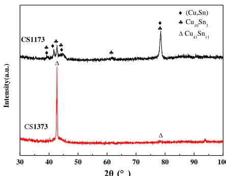
The rapidly solidified Cu75Sn25 alloys prepared at different injecting temperatures were examined by X-ray diffraction (XRD) cover the range from 30~100°, which are shown in Fig 1.
30 40 50 60 70 80 90 100
(Cu,Sn)
Cu
10Sn3
Cu
41Sn11
CS1173 CS1373 In te n si ty (a .u .)
2θ (° )
[image:3.596.185.407.186.359.2]
Figure 1. XRD diffraction patterns of rapidly solidified CuSn alloy at different injecting temperature
In Fig 1, X-ray diffraction shows that the structures are different for two rapidly solidified CuSn prepared at different injecting temperature. The intermetallic compound Cu10Sn3 (P63/173) formed in addition to the formation of (Cu,Sn) (Pmmn/59) phase for CS1173 alloy and CS1373 alloy was composed of intermetallic compound Cu41Sn11 (F-43m/216).
From the peak position and the half-height width of the X-ray diffraction peak, The mean crystallites average sizes of two alloys have been calculated using the Scherrer equation[16-18], and the results are shown in Tab 1.
d =kλ/(bcosθ) (1)
where d is the crystalline size, k is a dimensionless number of the order unity, λ is the wavelength of the radiation, θ is the diffraction angle and b is the halfwidth at half height for the diffraction peak. In Tab1, it is clear that CS1173 alloy has smaller crystallite size compared with CS1373, which maybe results from the lower injecting temperature.
A four-point collinear probe method was used to measure resistivity of rapidly solidified CuSn alloy. Two probes were used for the current testing, and the other two were used for the voltage testing [19].The resistance of CS1373 and CS1173 alloys can be determined, and the resistivity of the alloy was calculated by the following equation. With four point probe method, the calculation formula of resistivity for rapidly solidified Cu75Sn25 alloy is shown as follows [19]:
ρ=R*S/L=(R*πr2
[image:4.596.97.492.179.251.2]
where ρ is the resistivity of sample, R is resistance, S is the area of cross section, L is the length of sample, r is the radius of cylindrical sample. The resistivity, phase and crystalline size of rapidly solidified Cu75Sn25 alloy are shown in Tab 1.
Table 1. Phase composition, crystalline size and resistivity of rapidly solidified Cu75Sn25 alloys
Sample Injection
temperature Phase
Crystalline size(Å)
Resistivity (Ω.m) CS1173 1173K Cu10Sn3+(Cu,Sn) 259 0.3367×10⁻³
CS1373 1373K Cu41Sn11 599 3.376×10⁻³
In comparison with CS11377 alloy, the rapidly solidified CS1373 has higher resistivity nearly an order of magnitude compared with CS1173 alloy. Anything increases the frequency of collisions with ions and decreases the free electrons will raise the resistivity such as thermal vibrations, foreign atoms in solid solution, plastic deformation of the lattice and formation of intermetallic compound [18]. There may be several reasons for the higher resistivity of CS1373 alloy. The formation of intermetallic compounds always leads to the increase of resistivity due to the decrease of conduction electrons. Thus the formation of intermetallic compounds increases the electrical resistivity, as well as, these enclosures as scattering centers for the electrons [18]. From XRD results, it is clear that an intermetallic compound Cu41Sn11 forms in CS1373 alloy while there are (Cu,Sn) phase except the intermetallic compound Cu10Sn3 in CS1173 alloy. The formation of more intermetallic compound in CS1373 alloy results in more decrease of conduction electrons, which increase the resistivity. On the other hand, the smaller crystalline size of CS1173 alloy produces more crystalline boundary, which increase the frequency of collisions with ions and lead to higher resistivity.
3.2 Electrochemical properties
In order to investigate the corrosion property of rapidly solidified Cu75Sn25 alloy in different solutions, the electrochemical behavior of two samples were
analyzed by polarization curves and electrochemical impedance spectroscopy.
3.2.1 Potentiodynamic polarization
[image:5.596.159.437.310.514.2]
Figure 2. Polarization curves of rapidly solidified Cu75Sn25 alloys in H2SO4 solution
Figure 3. Polarization curves of rapidly solidified Cu75Sn25 alloys in NaOH solution
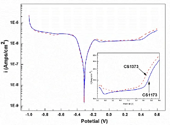
In Fig 2, the polarization curves of rapidly solidified Cu75Sn25 alloys in H2SO4 solution are similar to that of Sn-0.75Cu solder joints in NaCl solution [20].
Table 2. Potentiodynamic polarization parameters for rapidly solidified Cu75Sn25 alloy
Sample Solutions Ba Bc Ecorr (mv)
Icorr
(μA/cm2 )
Ep
(mv)
Ip
(μA/cm2 )
△Epd
(mv)
CS1173 H2SO4 63.9 367.1 -131 0.52 1585.7 27.9 1338.8
CS1373 H2SO4 70.82 381.6 -92 1.27 1476.4 44.1 1216.4
CS1173 NaOH 101.3 68.7 -316 0.1 411.3 1.51 518.6
[image:5.596.65.532.651.765.2]
As we known, higher Icorr represents higher corrosion rate of system and more positive
corrosion potential means lower thermodynamic tendency of corrosion [21]. It can be seen from Tab 2, CS1173 alloy possesses lower corrosion current (Icorr =0.52μA/cm2) compared with CS1373 alloy
(Icorr =1.27μA/cm2) in 0.1mol/L H2SO4 solution. And the anodic and cathodic processes slopes of
CS1173 alloy are smaller than that of CS1373 alloy in H2SO4 solution which shows the anodic and cathodic processes of CS1373 alloy corrosion in solution were suppressed effectively by the phase transition from Cu10Sn3+(Cu,Sn) to Cu41Sn11 for rapidly solidified CuSn alloy. And the converse trend occurred in NaOH solution. The results indicate CS1173 alloy has more excellent corrosion resistance than CS1373 alloy from the view of corrosion dynamic in H2SO4 solution [22].
In Fig 2, after the maximum current peak on the anode curve, the current decrease abruptly, and then a passivation period occurred for CS1173 and CS1373 alloys. The current decreases to some extent due to formation of passive film on electrode surface, which has protective effect and reduces the active dissolution of metals from the surface. However, it is clear that there is a small oxidation peak at about 950mv during the passivation period for CS1373 alloy while no peak for CS1173 alloy. The current increases and decreases soon accompanied with a small increase of potential, which possibly due to the redox transformation from Cu+ to Cu2+.
Passive films are susceptible to localized damage caused by mechanical and chemical effects [23]. The chemical effect responsible for the developed of localized dissolution and oxide film breakdown (pitting corrosion) were ever analyzed [24-25]. In Fig 2, a break in the passive region is observed for CS1173 and CS1373 alloys in H2SO4 solution. Combining Fig 2 and Tab 2, CS1173 alloy has higher pitting potential (Ep), lower pitting current (Ip) and passivation domain (△Epd) than CS1373
alloy, which suggest CS1173 alloy has higher passivation capability and protection performance of the passive film than CS1373 alloy.
In Fig 3, the anodic polarization curves of CS1173 and CS1373 alloys have same shape and typical passive behavior in NaOH solution, which indicate the formation of passive film on the surface. In Tab 2, though the corrosion potential Ecorr of CS 1173 and CS1373 alloys has no clear difference
between CS 1173 and CS1373 alloys, CS1373 alloy has lower corrosion current (Icorr =0.06μA/cm2 )
than CS1173 alloy (Icorr =0.1μA/cm2) in 0.1mol/L NaOH solution. The results suggest CS1373 alloy
has better corrosion resistance than CS1173 alloy in NaOH solution, which has a contrary trend compared with that in H2SO4 solution. Whereas, the passive domain (△Epd) of CS1173 alloy is more extensive than that of CS1373 alloy, which means it’s passive film exist steadily in more wider potential.
3.2.2 Electrochemical impedance spectroscopy
0.1mol/L H2SO4 and 0.1mol/L NaOH solutions. As known, EIS spectra is usually displayed in the form of a Nyquist plot or a Bode plot [27].
3.2.2.1 Corrosion behavior in H2SO4 solution
[image:7.596.122.477.236.505.2]The Nyquist plots of rapidly solidified Cu75Sn25 alloy in 0.1mol/L H2SO4 at ambient temperature are presented in Fig.4. It is obvious that CS1373 and CS1173 alloy exhibited similar behavior in H2SO4 solution.
Figure 4. Nyquist plots of rapidly solidified Cu75Sn25 alloys in H2SO4 solution
A well-known equivalent circuit R(QR)(QR) model has been adopted in order to provide quantitative support to the present experimental EIS results of rapidly solidified Cu75Sn25 alloys in H2SO4 solution. The circuit was shown in Fig 5. The process can be modeled as a constant phase element of passive film in parallel with a film resistor, which is in parallel with a circuit containing a constant phase element of double electric layer capacitor with a charge-transfer resistor, all in series with solution resistance. Using this equivalent circuit and ZView software, the impedance parameters have been obtained, which are shown in Tab 3. Rs is the solution resistance; Qpf is the capacitance of
passive film; Rpf is the resistance of passive film; Rct is charge-transfer resistance; QdI is double-layer
[image:8.596.43.552.251.322.2]
Figure 5. Equivalent circuits of rapidly solidified Cu75Sn25 alloys
Table 3. Impedance parameters of rapidly solidified Cu75Sn25 alloys in H2SO4 solution
R(QR)(QR) RS
(ohm-cm2)
Qpf-YO npf Rpf
(ohm-cm2)
QdI-YO ndI Rct
(ohm-cm2)
CS1173 8.68 1.04E-2 0.8 936.5 2.55E-4 0.8 515.2
CS1373 6.499 0.47E-2 0.57 834.5 4.5E-4 0.79 261.2
Compared to CS1373 alloy, n of CS1173 alloy is higher, which mean the surface of CS1173 has lower roughness than that of CS1373 alloy. The values of charge-transfer resistance (Rct) is a
parameter relative to corrosion rate, the higher Rct means lower corrosion rate. In Tab3, it is obvious
that CS1173 alloy has higher charge resistance Rct (515.2) than CS1373 alloy (261.2), which indicates
the corrosion rate of CS1173 alloy is lower than CS1373 alloy. The diameter of the semicircles is associated with the film resistance (Rpf) which may be correlated to the rate of corrosion: the larger is
the resistance, the lower is the rate of corrosion [29]. And the higher resistance of passive film Rpf
(936.5) of CS1173 than that (834.5) of CS1373 alloy, which further confirm it.
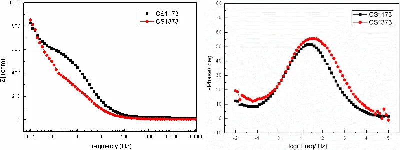
Figure 6. Bode plots of rapidly solidified Cu75Sn25 alloy in H2SO4 solution
The corrosion behavior of the rapidly solidified Cu75Sn25 alloy in H2SO4 solution is further illustrated by Bode plots in Fig 6. The values of |z| of CS1173 alloy are significantly higher than that of CS1373 alloy, which indicate the passive film formed on CS1173 alloy is more protective. It
Q
dI
Q
pf
R
ct
R
pf
[image:8.596.99.501.514.664.2]
confirmed that CS1173 provides better corrosion protection than CS1373 in H2SO4 solution, which is agreed with the results obtained from its polarization curves [30].
3.2.2.2 Corrosion behavior in NaOH solution
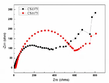
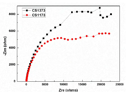
[image:9.596.172.426.218.404.2]The Nyquist plots of rapidly solidified Cu75Sn25 alloy in 0.1mol/L H2SO4 at ambient temperature were presented in Fig 7.
Figure 7. Nyquist plots of rapidly solidified Cu75Sn25 alloy in NaOH solution
[image:9.596.73.524.573.652.2]The same equivalent circuit R(QR)(QR) was used to model the rapidly solidified electrode and the electrolyte surface in 0.1mol/L NaOH solution. The values of impedance parameters are obtained by fitting the impedance data with Zview software using the proposed circuit, which were shown in Tab 4.
Table 4. Impedance parameters of rapidly solidified Cu75Sn25 alloys in NaOH solution R(QR)(QR) RS
(ohm-cm2) Qpf
-YO
npf Rpf
(ohm-cm2)
QdI-YO ndI Rct
(ohm-cm2) CS1173 8.41 2.16E-4 0.8445 1.56E4 4.867E-5 0.8501 7.1E3 CS1373 7.59 1.15E-4 0.8852 2.85E5 1.266E-4 0.8672 2.181E4
In Tab 4, it is clear that the resistance of passive film Rpf of CS1373 and CS1173 alloy is
higher, which appears to have similar stable film to protect the surface. However, the increased Rct
4. CONCLUSION
The rapidly solidified Cu75Sn25 alloys were prepared at injecting temperature of 1173K (CS1173 alloy) and 1373K (CS1373 alloy) respectively. The intermetallic compound Cu10Sn3 and (Cu,Sn) phase formed for CS1173 alloy while CS1373 alloy was composed of intermetallic compound Cu41Sn11. CS1173 alloy has lower resistivity compared to CS1373 alloy, which may be due to the formation of intermetallic compound and crystalline size.
Polarization and EIS test results indicated passive films formed on rapidly Cu75Sn25 alloy in H2SO4 and NaOH solutions. In H2SO4 solution, CS1373 alloy has more stable passive film formed compared to CS1173 alloy. CS1173 alloy has more excellent corrosion resistance than CS1373 alloy and it is inferred that there is a transition from Cu+ to Cu2+ in passive film on the surface of CS1373 alloy. However, CS1373 alloy has better corrosion resistance than CS1173 alloy in NaOH solution while it has a contrary trend compared with that in H2SO4 solution.
ACKNOWLEDGMENTS
This work was financially supported by the Basic Research Program of Jiangsu Province (Nos. BK20130304, BK20140334 and BK20140315), the National Natural Science Foundation of China (Nos.51204115 and 51401139), the Natural Science Foundation of the Jiangsu Higher Education Institutions of China (Grant No. 14KJB460024) and the Project Funded by China Postdoctoral Science Foundation (Grant No. 2014M561707).
Reference
1. D. Li , P. Franke, S. Fürtauer, D. Cupid, H. Flandorfer, Intermetallics, 34 (2013) 148-158. 2. O. Galdikiene, Z. Mockns, J. Appl. Electrochem, 24 (1994) 1009.
3. A. Brenner, Electrodeposition of Alloys, vol. 1, Academic Press, New York, 1963, 497. 4. W. Pu, X. He, J. Ren, C. Wan, C. Jiang, Electrochim. Acta. 50 (2005) 4140-4145.
5. J.S. Thorne, J.R. Dahn, M.N. Obrovac, R.A. Dunlap, J. Power Sources 216 (2012) 139-144. 6. R.M. Gnanamuthu, S. Mohan, C.W. Lee, Mater. Lett. 84 (2012) 101-103.
7. T. Beldjoudi, F. Bardet, N. Lacoudre, S. Andrieu, A. Adriens, I. Constantinides, P.Brunella, Rev. Metall. Paris 98 (2001) 803-808.
8. Sultan Öztürk, BülentÖztürk, FatihErdemir, GönülUsta. J. Mater. Process. Technol. 211 (2011) 1817-1823.
9. C.A. Loto, O. O. Joseph, R.T. Loto, A.P.I. Popoola. Int. J. Electrochem. Sci.,9(2014)1221-1231. 10.Tao Zhoua, Zhenhua Chen, Mingbo Yang, Jianjun Hua, Hua Xia,Mater. Charact., 63 (2012)
77-82.
11.Iuliana Lichioiu, Ildiko Peter, Bela Varga, Mario Rosso, J. Mater. Sci. Technol., 30(4) (2014) 394-400.
12.Yucel Birol, J. Alloys Compd., 439 (2007) 81-86.
13.JiXin Hou, Hong Xuan Guo, Cheng Wei Zhan, Xue Lei Tian, Xi Chen Chen. Mater. Lett., 60 (2006) 2038-2041.
14.X.Y. Xue, X.F. Bian, H.X.Geng& et al. Mater. Sci. Technol. 19 (2003) 557-560.
15.Xian-Ying Xue,Xiu-Fang Bian,Hong-Xia Geng& et al. Mater. Sci. Engi A. 363(1-2) (2003) 134-139.
18.A.R. Lashin , M. Mossa, A. El-Bediwi , M. Kamala, Mater. Des. 43 (2013) 322-326.
19.Xuefeng Liu, JihuiLuo, Xiaochen Wang, Lin Wang, JianxinXie. Progress in Natural Science: Materials International, 23(1) (2013) 94-101.
20.Gao Yan-fang, Cheng Cong-qian, Zhao Jie, Wang Li-hua, LI Xiao-gang, Trans. Nonferrous Met. Soc. China, 22 (2012) 977-982.
21.Zhe Liu, Zhenhua Chu, Yanchun Dong, YongYang, Xueguang Chen, Xiangjiao Kong, DianranYan. Vacuum, 101(2014) 6-9.
22.Kou Hong cha, Li Yon, Zhang Tie-ban, Li Jian, Li Jinshan, Trans.Nonferrous Met. Soe. China, 21 (201I) 552-557.
23.F. Rosalbino, R. Carlini, R. Parodi, G. Zanicchi, G. Scavino, Corros. Sci., 85 (2014) 394-400. 24.Z. Szklarska-Smialowska, Pitting Corrosion of Metals, Nace, Houston (1986)
25.Z.Y. Liu, X.G. Li, Y.F. Cheng,Zhu X L, Sandenbergh R F, Electrochim. Acta, 60 (2012) 259-263. 26.F. Mansfeld, Electrochim. Acta, 35 (1990) 1533-1544.
27.Qiongyu Zhou, Jibo Jiang, Qingdong Zhong, Yi Wang, Ke Li, Huijuan Liu, J. Alloys Compd., 563 (2013) 171-175.
28.Ali A. Ensafi, A. Arabzadeh, H. Karimi-Maleh. S J. Braz. Chem. Soc. 21(8) (2010) 1572-1580. 29.Liana Anicai, Aurora Petica, Stefania Costovici, Paula Prioteasa, Teodor Visan, Electrochim. Acta,
114 (2013) 868-877.
30.B. Subramanian, S. Mohan, Sobha Jayakrishnan, Surf. Coat. Technol., 201 (2006) 1145-1151.