Amplifying the response of soft actuators
by harnessing snap-through instabilities
The Harvard community has made this
article openly available.
Please share
how
this access benefits you. Your story matters
Citation
Overvelde, Johannes T. B., Tamara Kloek, Jonas J. A. D’haen, and
Katia Bertoldi. 2015. “Amplifying the Response of Soft Actuators by
Harnessing Snap-through Instabilities.” Proc Natl Acad Sci USA 112
(35) (August 17): 10863–10868. doi:10.1073/pnas.1504947112.
Published Version
doi:10.1073/pnas.1504947112
Citable link
http://nrs.harvard.edu/urn-3:HUL.InstRepos:27657494
Terms of Use
This article was downloaded from Harvard University’s DASH
repository, and is made available under the terms and conditions
applicable to Other Posted Material, as set forth at http://
Amplifying the response of soft actuators by
harnessing snap-through instabilities
Johannes T. B. Overveldea, Tamara Kloeka, Jonas J. A. D’haena, and Katia Bertoldia,b,1
aJohn A. Paulson School of Engineering and Applied Sciences, Harvard University, Cambridge, MA 02138; andbKavli Institute, Harvard University,
Cambridge, MA 02138
Edited by John W. Hutchinson, Harvard University, Cambridge, MA, and approved July 21, 2015 (received for review March 11, 2015)
Soft, inflatable segments are the active elements responsible for the actuation of soft machines and robots. Although current designs of fluidic actuators achieve motion with large amplitudes, they require large amounts of supplied volume, limiting their speed and compactness. To circumvent these limitations, here we embrace instabilities and show that they can be exploited to amplify the response of the system. By combining experimental and numerical tools we design and construct fluidic actuators in which snap-through instabilities are harnessed to generate large motion, high forces, and fast actuation at constant volume. Our study opens avenues for the design of the next generation of soft actuators and robots in which small amounts of volume are sufficient to achieve significant ranges of motion.
soft actuator
|
snap-through instability|
fluidic segment|
amplificationT
he ability of elastomeric materials to undergo large de-formation has recently enabled the design of actuators that are inexpensive, easy to fabricate, and only require a single source of pressure for their actuation, and still achieve complex motion (1–5). These unique characteristics have allowed for a variety of innovative applications in areas as diverse as medical devices (6, 7), search and rescue systems (8), and adaptive robots (9–11). However, existing fluidic soft actuators typically show a continuous, quasi-monotonic relation between input and output, so they rely on large amounts of fluid to generate large deformations or exert high forces.By contrast, it is well known that a variety of elastic instabilities can be triggered in elastomeric films, resulting in sudden and significant geometric changes (12, 13). Such instabilities have traditionally been avoided as they often represent mechanical failure. However, a new trend is emerging in which instabilities are harnessed to enable new functionalities. For example, it has been reported that buckling can be instrumental in the design of stretchable soft electronics (14, 15), and tunable metamaterials (16–18). Moreover, snap-through transitions have been shown to result in instantaneous giant voltage-triggered deformation (19, 20). Here, we introduce a class of soft actuators comprised of inter-connected fluidic segments, and show that snap-through instabilities in these systems can be harnessed to instantaneously trigger large changes in internal pressure, extension, shape, and exerted force. By combining experiments and numerical tools, we developed an ap-proach that enables the design of customizable fluidic actuators for which a small increment in supplied volume (input) is sufficient to trigger large deformations or high forces (output).
Our work is inspired by the well-known two-balloon experiment, in which two identical balloons, inflated to different diameters, are connected to freely exchange air. Instead of the balloons becoming equal in size, for most cases the smaller balloon becomes even smaller and the balloon with the larger diameter further increases in volume (Movie S1). This unexpected behavior originates from the balloons’ nonlinear relation between pressure and volume, characterized by a pronounced pressure peak (21, 22). Interest-ingly, for certain combinations of interconnected balloons, such nonlinear response can result in snap-through instabilities at constant volume, which lead to significant and sudden changes of the membranes’diameters (Figs. S1andS2). It is straightforward to show analytically that these instabilities can be triggered only if the pressure–volume relation of at least one of the membranes
is characterized by (i) a pronounced initial peak in pressure, (ii) subsequent softening, and (iii) a final steep increase in pressure (Analytical Exploration: Response of Interconnected Spherical Membranes Upon Inflation).
Highly Nonlinear Fluidic Segments
To experimentally realize inflatable segments characterized by such a nonlinear pressure–volume relation, we initially fabricated fluidic segments that consist of a soft latex tube of initial lengthLtube, inner
radiusR=6.35 mm, and thicknessH=0.79 mm. We measured the pressure–volume relation experimentally for three segments with Ltube=22−30 mm, and found that their response is not affected by
their length (Fig. S3). Moreover, the response does not show a final steep increase in pressure. This is because latex has an almost linear behavior, even at large strains.
Next, to construct fluidic segments with a final steep increase in pressure and a response that can be easily tuned and con-trolled, we enclosed the latex tube by longer and stiffer braids of lengthLbraid(Fig. 1A). It is important to note that the effect of
the stiff braids is twofold. First, asLbraid>Ltube, the braids are in
a buckled state when connected to the latex tube (Fig. 1B), and therefore apply an axial force,F, to the membrane. Second, at a certain point during inflation when the membrane and the braids come into contact, the overall response of the segments stiffens. We derived a simple analytical model to predict the effect of LbraidandLtubeon the nonlinear response of these braided fluidic
segments (Simple Analytical Model to Predict the Response of the Fluidic Segments). It is interesting to note that our analysis in-dicates that for a latex tube of given length, shorter braids lower the peak pressure due to larger axial forces (Fig. S4C andE). Moreover, it also shows thatLbraidstrongly affects the volume at
which stiffening occurs. In fact, the shorter the braids, the earlier contact between the braids and the membrane occurs, reducing the amount of supplied volume required to have a steep increase
Significance
Although instabilities have traditionally been avoided as they often represent mechanical failure, here we embrace them to amplify the response of fluidic soft actuators. Besides pre-senting a robust strategy to trigger snap-through instabilities at constant volume in soft fluidic actuators, we also show that the energy released at the onset of the instabilities can be harnessed to trigger instantaneous and significant changes in internal pressure, extension, shape, and exerted force. There-fore, in stark contrast to previously studied soft fluidic actuators, we demonstrate that by harnessing snap-through instabilities it is possible to design and construct systems with highly control-lable nonlinear behavior, in which small amounts of fluid suffice to generate large outputs.
Author contributions: J.T.B.O. and K.B. designed research; J.T.B.O., T.K., and J.J.A.D. performed research; J.T.B.O., T.K., and K.B. analyzed data; and J.T.B.O. and K.B. wrote the paper.
The authors declare no conflict of interest.
This article is a PNAS Direct Submission.
1To whom correspondence should be addressed. Email: [email protected].
This article contains supporting information online atwww.pnas.org/lookup/suppl/doi:10. 1073/pnas.1504947112/-/DCSupplemental.
ENGIN
in pressure. Conversely, if Lbraidis fixed, and the length of the
membrane is varied, both the pressure peak and the volume at which stiffening occurs remain unaltered (Fig. S4F). However, in this case we find that shorter tubes lower the pressure of the softening region. Finally, the analytical model also indicates that the length of the fluidic segments,l=λzLtube, initially increases upon inflation (Fig.
S4EandF). However, when the tube and braids come into contact, further elongation is restrained by the braids and the segments shorten as a function of the supplied volume.
Having demonstrated analytically that fluidic segments with the desired nonlinear response can be constructed by enclosing a latex tube by longer and stiffer braids, and that their response can be controlled by changingLbraidandLtube, we now proceed to
fabricate such actuators. The stiffer braids are made from poly-ethylene-lined ethyl vinyl acetate tubing, with an inner radius of 7.94 mm and a thickness of 1.59 mm. Eight braids are formed by partly cutting this outer tube along its length guided by a 3D printed socket. Finally, Nylon Luer lock couplings (one socket and one plug) are glued to both ends of the fluidic segments to enable easy connection (Fig. 1A). We then measure their response ex-perimentally by inflating them with water at a rate of 60 mL/min, ensuring quasi-static conditions (Fig. 1BandMovie S2).
We fabricated 36 segments with Lbraid=40−50 mm and
Ltube=20−30 mm. As shown in Fig. 1C, all fluidic segments
are characterized by the desired nonlinear pressure—volume relation and follow the trends predicted by the analytical model (Fig. S4E and F). In particular, we find that for the 36 tested segments the initial peak in pressure ranges between 65 and 85 kPa (Fig. 1C). We also monitored the length of the segments during inflation (Fig. 1D). As predicted by the analytical model, we find that initially the seg-ments elongate, but then shorten when the tube and braids come into contact. It is important to note that no instabilities are triggered upon inflation of the individual segments, because the supplied volume is controlled, not the pressure.
Combined Soft Actuator
Next, we created a new, combined soft actuator by interconnecting the two segments whose individual response is shown in Fig. 2A. Upon inflation of this combined actuator, very rich behavior
emerges (Fig. 2C and Movie S3). In fact, the pressure–volume
response of the combined actuator is not only characterized by two peaks, but the second peak is also accompanied by a significant and instantaneous elongation. This suggests that an instability at con-stant volume has been triggered.
Numerical Algorithm.To better understand the behavior of such
combined actuators, we developed a numerical algorithm that accurately predicts the response of systems containingnsegments, based solely on the experimental pressure–volume curves of the individual segments. By using the 36 segments from experiments as building blocks, we can construct 36!=½ð36−nÞ!n!combined actuators comprising n segments (i.e., 630 different combined actuators forn=2; 7,140 forn=3; and 58,905 forn=4), where we assume that the order in which we arrange the segments does not matter. It is therefore crucial to implement a robust algorithm to efficiently scan the range of responses that can be achieved.
We start by noting that, upon inflation, the state of the ith segment is defined by its pressurepiand volumevi, and its stored
elastic energy can be calculated as
EiðviÞ=
Zvi
Vi
pið~vÞd~v, [1]
in which we neglect dynamic effects. Moreover, Vi denotes the
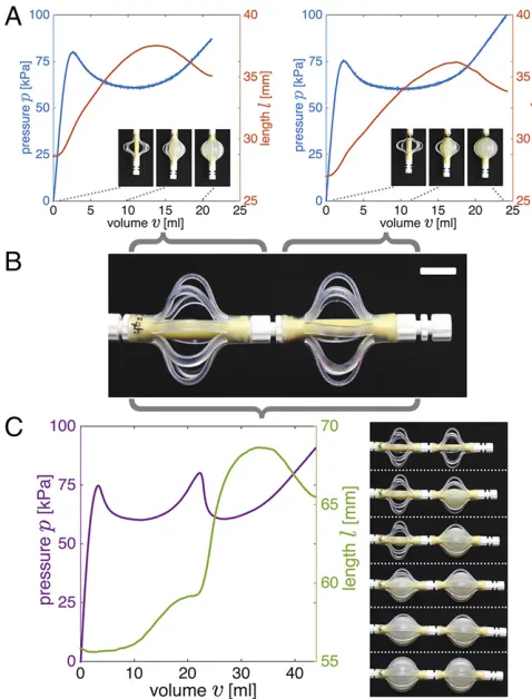
[image:3.585.58.275.50.273.2]volume of theith segment in the unpressurized state. When the Fig. 1. (A) Outer and stiffer braids are added to the latex tube to create fluidic
segments with highly nonlinear response. (B) Snapshots of a segment charac-terized byðLbraid,LtubeÞ=ð46, 20Þduring inflation atv=0, 10, 20 mL.
Evolu-tion of (C) pressure (p) and (D) length (l) as a function of the supplied volume (v) for 36 fluidic segments characterized byLbraid=40−50 mm andLtube=
20−30 mm. (Scale bars: 10 mm.)
Fig. 2. (A) Evolution of pressure (p) and length (l) as a function of the supplied volume (v) for two fluidic segments characterized byðLbraid,LtubeÞ=ð46, 20Þand ð46, 22Þ mm. Snapshots of the fluidic segments at v=0, 10, 20 and v=
0, 12, 24 mL are shown asInsets, respectively. (B) The two fluidic segments are connected to form a new, combined soft actuator. (C) Evolution of pressure (p) and length (l) as a function of the supplied volume (v) for the combined actuator. Snapshots of the combined actuator atv=0, 9, 18, 27, 36, 45 mL are shown asInsets.
[image:3.585.301.540.344.658.2]total volume of the system,v=Pni=1vi, is controlled (as in all our
experiments), the response of the system is characterized byn−1 variablesv1,. . .,vn−1and the constraint
vn=v−
Xn−1
i=1
vi. [2]
To determine the equilibrium configurations, we first define the elastic energy,E, stored in the system, which is given by the sum of the elastic energy of the individual segments
Eðv1,. . .,vnÞ=
Xn i=1
Zvi
Vi
pið~vÞd~v, [3]
and use Eq.2to express the energy in terms ofn−1 variables
~
Eðv1,. . .,vn−1Þ=
Xn−1
i=1
Zvi
Vi
pið~vÞd~v+
Z
v−Pni=−11vi
Vn
pnð~vÞd~v. [4]
Next, we implement a numerical algorithm that finds the equi-librium path followed by the actuator upon inflation (i.e., increasing v). Starting from the initial configuration (i.e., vi=Vi), we
in-crementally increase the total volume of the system (v) and locally minimize the elastic energy (E). Because Eq.~ 4already takes into account the volume constraint (Eq.2), we use an unconstrained optimization algorithm such as the Nelder–Mead simplex algorithm implemented in Matlab (23). Note that this algorithm looks only locally for an energy minimum, similar to what happens in the ex-periments, and therefore it does not identify additional minima at the same volume that may appear during inflation.
Using the aforementioned algorithm, we find that for many ac-tuators the energy can suddenly decrease upon inflation, indicating that a snap-through instability at constant volume has been trig-gered. To fully unravel the response of the actuators, we also detect all equilibrium configurations and evaluate their stability. The equilibrium states for the system can be found by imposing
∂E~ ∂vi=
0, ∀i∈f1,. . .,n−1g. [5]
Substitution of Eq.4into Eq.5, yields ∂E~
∂vi=
piðviÞ−pn v−
Xn−1
j=1 vj
!
=0, ∀i∈f1,. . .,n−1g,
[6]
which, when substituting Eq.2, can be rewritten as
p1ðv1Þ=p2ðv2Þ=. . .=pnðvnÞ. [7]
As expected, Eq.7ensures that the pressure is the same in alln segments connected in series.
Operationally, to determine all of the equilibrium configura-tions of a combined soft actuator comprisingnfluidic segments, we first define 1,000 equispaced pressure points between 0 and 100 kPa. Then, for each of thensegments we find all volumes that result in those values of pressure (Fig. S5A). Finally, for each value of pressure, we determine the equilibrium states by making all possible combinations of those volumes (Fig. S5B). Note that by using Eq.2we can also determine the total volume in the system at each equilibrium state, and then plot the pres-sure–volume response for the combined actuator (Fig. S5C).
Finally, we check the stability of each equilibrium configura-tion. Because an equilibrium state is stable when it corresponds
to a minimum of the elastic energy E~defined in Eq. 4, at any stable equilibrium solution the Hessian matrix
HE~ðv1,. . .,vn−1Þ=
2 6 6 6 6 6 6 6 6 4
∂2E~ ∂v2 1
. . . ∂v1∂v∂2E~
n−1
... ⋱ ...
∂2E~ ∂vn−1∂v1 . . .
∂2E~ ∂v2
n−1
3 7 7 7 7 7 7 7 7 5 [8]
is positive definite. Note that the second-order partial derivatives in Eq.8can be evaluated as
∂2E~ ∂vi∂vj=
8 > > > > < > > > > :
pi′ðviÞ+pn′ v−
Xn−1
k=1 vk
!
, if i=j pn′ v−
Xn−1
k=1 vk
!
, if i≠j,
[image:4.585.289.540.190.617.2][9]
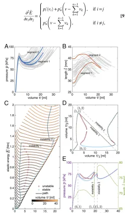
Fig. 3. (A) Experimentally measured pressure–volume relations for all 36 fab-ricated fluidic segments. (B) Experimentally measured length–volume relations for all 36 fabricated segments. (C) Numerically determined elastic energy,E, for a combined actuator comprising the two segments whose individual behavior is highlighted inAandB. The energy is shown for increasing values of the supplied volume,v. The stable and unstable equilibrium configurations are highlighted by blue and red circular markers, respectively. (D) Equilibrium configurations for the combined actuators. Atv=19 mL an unstable (1, 1) transition is found, resulting in a significant internal volume flow. A second instability of type (1, 2) is then triggered atv=22 mL. (E) Numerically determined pressure–volume and length–
volume relations for the combined soft actuator.
ENGIN
in whichpi′ð~vÞ=dpi=d~v. Taking advantage of the fact that all
off-diagonal terms of the Hessian matrix are identical and using Sylvest-er’s criterion (24), we find that an equilibrium state is stable if
Y
i=1
k
pi′ðviÞ+pn′ v−
Xn−1
k=1 vk
! Xk
i=1
Yk j=1,j≠i
pj′
vj
>0, ∀k=1,. . .,n−1.
[10]
Numerical Results.To demonstrate the numerical algorithm, we
focus on two segments where the experimentally measured pressure–volume and length–volume responses are highlighted in Fig. 3AandB. In Fig. 3Cwe report the evolution of the total elastic energy of the system,E, as a function of the volume of the first segment,v1, for increasing values of the total supplied vol-ume,v, and in Fig. 3Dwe show all equilibrium configurations in thev1–v2plane. We find that initially (0<v<5 mL) the volume of both segments increases gradually. However, for 5<v<19 mL, v1 remains almost constant and all additional volume that is added to the system flows into the second segment. Moreover, at v=6 mL a second local minimum for E emerges, so that for 6<v<19 mL the system is characterized by two stable equilib-rium configurations. Although for v>13 mL this second mini-mum has the lowest energy, the system remains in the original energy valley untilv=19 mL. At this point the local minimum of Ein which the system is residing disappears, so that its equilib-rium configuration becomes unstable, forcing the actuator to snap to the second equilibrium characterized by a lower value of E. Interestingly, this instability triggers a significant internal volume flow from the second to the first segment (Fig. 3D) and a sudden increase in length (Fig. 3E). Further inflating the system tov=22 mL triggers a second instability, at which some volume suddenly flows back from the first to the second segment. After this second instability, increasing the system’s volume further inflates both segments simultaneously.
All transitions that take place upon inflation (i.e., atv=5, 19, and 22 mL) are highlighted by a peak in the pressure–volume curve (Fig. 3E), and correspond to instances at which one or more of the in-dividual segments cross their own peak in pressure. These state transitions can either be stable or unstable (Fig. 3C–E). A stable transition always leads to an increase of the elastic energy stored in the system, and an instability results in a new equilibrium configu-ration with lower energy. Each state transition can therefore be characterized by the elastic energy release, which we define as a normalized scalar ΔE^=ðEpost−EpreÞ=Epre. Here and in the
fol-lowing, the subscriptspreandpostindicate the values of the quantity immediately before and after the state transition. Moreover, to better understand the effects of each transition on the system, we
define the associated normalized changes in internal volume distribution, length and pressure asΔ^v=max
i ðvi,post−vi,preÞ=vpre,
Δ^l=ðlpost−lpreÞ=ðlpreÞandΔ^p=ðppost−ppreÞ=ppre.
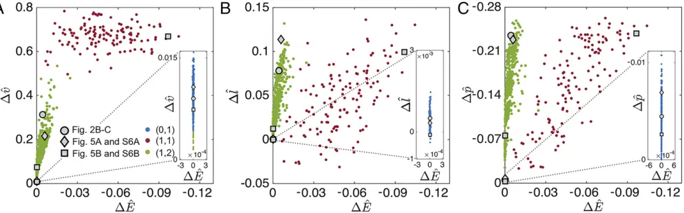
In Fig. 4 we report Δ^v, Δ^l, and Δ^p versus the normalized change in energy, ΔE, for all transitions that occur in the 630^ combined soft actuators comprising n=2 segments. Note that there are more than 630 data points, because all actuators show two or more state transitions. We find that−0.1≤ΔE^≤4 · 10−5, indicating that some of the transitions are stable (i.e.,ΔE^>0), and others are unstable (ΔE^<0). We furthermore observe that the energy increase for stable transitions is very small, and is therefore sensitive to the increment size used in the numerical algorithm. By contrast, the elastic energy released during un-stable transitions can be as high as 10% of the stored energy.
We also characterize each state transition according to the changes induced in the individual segments, and use ðα,βÞ to identify the number of segments to the right of their pressure peak before (α) and after (β) the state transition. For combined soft actuators comprising n=2 segments, the numerical results show three possible types of transitions: ð0, 1Þ, in which both segments are initially on the left of their peak in pressure and then one of them crosses its pressure peak during the state transition (blue markers in Fig. 4); ð1, 2Þ, in which the second segment also crosses its peak in pressure (green markers in Fig. 4);ð1, 1Þ, in which both segments cross their pressure peak, but one while inflating and the other while deflating (red markers in Fig. 4). We find that transitions of typeð0, 1Þoccur in all com-bined actuators and are always stable. Therefore, the associated changes in elastic energy, length, pressure, and the internal vol-ume distribution are approximately zero. By contrast, transitions of typeð1, 1Þare always unstable and result in both high elastic energy release (up to 10%) and high internal volume flow (up to 80%). Unlikeð1, 1Þ, transitions of typeð1, 2Þcan be either stable or unstable. The unstable transitions result in moderate energy release (up to 2.5%), but can lead to significant and instantaneous changes in length (up to 14%). Therefore, our analysis clearly in-dicates not only that snap-through instabilities at constant volume can be triggered in soft fluidic actuators, but also that the associated released energy can be harnessed to trigger sudden changes in length, drops in pressure, and internal volume flows.
Experimental Results.To validate the numerical predictions, we
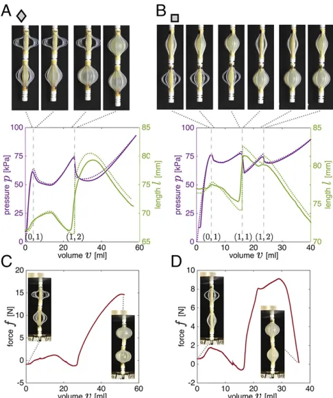
[image:5.585.50.547.549.704.2]measured experimentally the response of several combined ac-tuators. In Fig. 5A we show the results for the system whose predicted transitions are indicated by the diamond gray markers in Fig. 4. We compare the numerically predicted and experimen-tally observed mechanical response, finding an excellent agree-ment. In particular, for this combined actuator we find that the pressure–volume curve is characterized by two peaks, indicating
Fig. 4. A–CshowΔ^v,Δ^landΔp^versus the normalized change in energyΔ^Efor all state transitions that occur in the 630 combined soft actuators comprisingn=2 fluidic segments. Blue, red, and green markers correspond toð0, 1Þ,ð1, 1Þ, andð1, 2Þtransitions, respectively; (A)Δ^vversusΔE^; (B)Δ^lversusΔ^E; and (C)Δ^pversusΔE^.
that two transitions take place upon inflation. Although theð0, 1Þ transition is stable, theð1, 2Þtransition is unstable and results in an instantaneous and significant increase in length of 11% and a high pressure drop of 23% (Fig. 5A and Movie S4). This unstable transition is also accompanied by a moderate internal volume re-distribution of 22%, resulting in the sudden inflation of the top actuator (see snapshots in Fig. 5A and numerical result in
Fig. S6A).
In Fig. 5B we present the results for the combined actuator whose response is indicated by the square gray markers in Fig. 4. Our analysis indicates that one stableð0, 1Þtransition and two unstable transitions are triggered during its inflation. The first snap-through instability is að1, 1Þtransition and is accompanied by a significant and sudden volume redistribution (see snapshots in Fig. 5Band numerical result inFig. S6B) and a large increase in length (Movie S5), and the second instability is að1, 2Þ tran-sition and results in smaller values for Δ^l and Δ^v. Again, we observe an excellent agreement between experimental and nu-merical results, indicating that our modeling approach is accu-rate and can be used to effectively design soft actuators that harness instabilities to amplify their response.
Although the results reported in Fig. 5AandBare for actuators free to expand, these systems can also be used to exert large forces while supplying only small volumes. To this end, in Fig. 5CandDwe show the force measured during inflation when the elongation of the
actuators is completely constrained. We find that also in this case an instability is triggered, resulting in a sudden, large increase in the exerted force. Note that the volume at which the instability occurs is slightly different from that found in the case of free inflation. This discrepancy arises from the fact that the pressure–volume relation of each segment is affected by the conditions at its boundaries.
The proposed approach can be easily extended to study more complex combined actuators comprising a larger number of segments. By increasingn, new types of state transitions can be triggered. For example, transitions of typeð2,1Þare also observed for n=3 (Fig. S7A–C), in which two segments deflate into a single one, causing all three segments to cross their peak in pressure. In Fig. 6, we focus on an actuator that undergoes an unstableð2,1Þtransition atv=29 mL. We first inflate the actu-ator tov=28 mL, and then decouple it from the syringe pump and connect it to a small reservoir containing only 1 mL of water. Remarkably, by adding only 1 mL of water to the system, we are able to trigger a significant internal volume flow of∼20 mL that results in the deflation of two segments into one segment (Fig. 6 andMovie S6).These results further highlight that snap-through instability can be harnessed to amplify the effect of small inputs.
Conclusion
In summary, by combining experimental and numerical tools we have shown that snap-through instabilities at constant volume can be triggered when multiple fluidic segments with a highly nonlinear pressure–volume relation are interconnected, and that such un-stable transitions can be exploited to amplify the response of the system. In stark contrast to most of the soft fluidic actuators pre-viously studied, we have demonstrated that by harnessing snap-through instabilities it is possible to design and construct systems in which small amounts of fluid suffice to trigger instantaneous and significant changes in pressure, length, shape, and exerted force. To simplify the analysis, in this study we have used water to actuate the segments (due to its incompressibility). However, it is important to note that the actuation speed of the proposed actu-ators can be greatly increased by supplying air. In fact, we find that water introduces significant inertia during inflation, limiting the actuation speed. It typically takes more than 1 s for the changes in length, pressure, and internal volume induced by the instability to fully take place (Movie S7). However, by simply using air to actuate the system and by adding a small reservoir to increase the energy stored in the system, the actuation time can be significantly re-duced (fromΔt=1.4 to 0.1 s for the actuator considered inMovie S7), highlighting the potential of these systems for applications where speed is important. Although this actuation time is similar to that of recently reported high-speed soft actuators (3), only a small volume of supplied fluid is required to actuate the system because we exploit snap-through instabilities at constant volume. As a Fig. 5. (AandB) Experimental (solid lines) and numerical (dashed lines)
pressure–volume curves for two soft actuators comprisingn=2 fluidic seg-ments. (A) Results for a combined actuator withðLbraid,LtubeÞ=ð48, 30Þand ð50, 20Þmm. The transitions for this actuator are highlighted by diamond markers in Fig. 4. Snapshots of the combined actuators 0.5 mL before and after each state transition (atv=4, 26 mL) are also shown. (B) Results for a combined actuator withðLbraid,LtubeÞ=ð44, 30Þandð48, 26Þmm. The transitions for this
actuator are highlighted by square markers in Fig. 4. Snapshots of the combined actuators 0.5 mL before and after each state transition (atv=5, 16, 24 mL) are also shown. Experimentally measured exerted force as a function of the supplied volume for a combined actuator with (C)ðLbraid,LtubeÞ=ð48, 30Þand ð50, 20Þmm and (D) ðLbraid,LtubeÞ=ð44, 30Þ and ð48, 26Þ mm with
con-strained ends.
Fig. 6. Snapshots of a combined actuator withðLbraid,LtubeÞ=ð40,28Þ,ð44, 30Þ,
andð50, 24Þmm. The numerical analysis predicts að2, 1Þstate transition at
v=29 mL (see gray triangle inFig. S7A–C). The combined actuator is inflated tov=28 mL, and then decoupled from the syringe pump and connected to a small reservoir containing only 1 mL of water. An additional volume of 1 mL supplied to the system is enough to trigger a significant internal volume flow of∼20 mL that results in the deflation of two segments into one segment (Movie S6).
ENGIN
[image:6.585.331.508.551.650.2]result, small compressors are sufficient to inflate these actuators, making them highly suitable for untethered applications.
Our results indicate that by combining fluidic segments with designed nonlinear responses and by embracing their nonlinearities, we can construct actuators capable of large motion, high forces, and fast actuation at constant volume. Although here we have focused specifically on controlling the nonlinear response of fluidic actua-tors, we believe that our analysis can also be used to enhance the response of other types of actuators (e.g., thermal, electrical and mechanical) by rationally introducing strong nonlinearities. Our approach therefore enables the design of a class of nonlinear sys-tems that is waiting to be explored.
Materials and Methods
All individual soft fluidic segments and combined actuators investigated in this study are tested using a syringe pump (Standard Infuse/Withdraw PHD Ultra; Harvard Apparatus) equipped with two 50-mL syringes that have an accuracy of±0.1% (1000 series, Hamilton Company). The segments and the combined actuators are inflated at a rate of 60 and 20 mL/min, respectively,
ensuring quasi-static conditions. Moreover, during inflation the pressure is measured using a silicon pressure sensor (MPX5100; Freescale Semiconductor) with a range of 0–100 kPa and an accuracy of±2.5%, which is connected to a data acquisition system (NI USB-6009, National Instruments). The elongation of the actuators is monitored by putting two markers on both ends of each actu-ator, and recording their position every two seconds with a high-resolution camera (D90 SLR, Nikon). The length of the actuator is then calculated from the pictures using a digital image processing code in Matlab. Each experiment is repeated 5 times, and the final response of the actuator as shown in the paper is determined by averaging the results of the last four tests. Finally, we measured the force exerted by the actuators during inflation when their elongation is completely constrained. In this case we use a uniaxial materials testing machine (model 5544A; Instron, Inc.) with a 100-N load cell to measure the reaction force during inflation.
ACKNOWLEDGMENTS.This work was supported by the Materials Research Science and Engineering Center under National Science Foundation Award DMR-1420570. K.B. also acknowledges support from the National Science Foundation (CMMI-1149456-CAREER) and the Wyss institute through the Seed Grant Program.
1. Laschi C, Mazzolai B, Mattoli V, Cianchetti M, Dario P (2009) Design of a biomimetic robotic octopus arm.Bioinspir Biomim4(1):015006.
2. Ilievski F, Mazzeo AD, Shepherd RF, Chen X, Whitesides GM (2011) Soft robotics for chemists.Angew Chem Int Ed Engl50(8):1890–1895.
3. Mosadegh B, et al. (2014) Pneumatic networks for soft robotics that actuate rapidly.
Adv Funct Mater24:2163–2170.
4. Martinez RV, et al. (2013) Robotic tentacles with three-dimensional mobility based on flexible elastomers.Adv Mater25(2):205–212.
5. Martinez RV, Glavan AC, Keplinger C, Oyetibo AI, Whitesides GM (2014) Soft actuators and robots that are resistant to mechanical damage.Adv Funct Mater24:3003–3010. 6. Roche ET, et al. (2014) A bioinspired soft actuated material.Adv Mater26(8):
1200–1206.
7. Majidi C (2013) Soft Robotics: A perspective—Current trends and prospects for the future.Soft Robotics1:5–11.
8. Tolley MT, et al. (2014) A resilient, untethered soft robot.Soft Robotics1:213–223. 9. Shepherd RF, et al. (2011) Multigait soft robot.Proc Natl Acad Sci USA108(51):
20400–20403.
10. Morin SA, et al. (2012) Camouflage and display for soft machines.Science337(6096): 828–832.
11. Kim S, Laschi C, Trimmer B (2013) Soft robotics: A bioinspired evolution in robotics.
Trends Biotechnol31(5):287–294.
12. Singamaneni S, Tsukruk V (2010) Buckling instabilities in periodic composite poly-meric materials.Soft Matter6:5681–5692.
13. Chen D, Yoon J, Chandra D, Crosby AJ, Hayward RC (2014) Stimuli-responsive buckling mechanics of polymer films.J Polym Sci, B, Polym Phys52:1441–1461.
14. Rogers JA, Someya T, Huang Y (2010) Materials and mechanics for stretchable elec-tronics.Science327(5973):1603–1607.
15. Wang Y, et al. (2011) Super-elastic graphene ripples for flexible strain sensors.ACS Nano5(5):3645–3650.
16. Shim J, Perdigou C, Chen ER, Bertoldi K, Reis PM (2012) Buckling-induced encapsu-lation of structured elastic shells under pressure.Proc Natl Acad Sci USA109(16): 5978–5983.
17. Florijn B, Coulais C, van Hecke M (2014) Programmable mechanical metamaterials.
Phys Rev Lett113(17):175503.
18. Wang P, Casadei F, Shan S, Weaver JC, Bertoldi K (2014) Harnessing buckling to design tunable locally resonant acoustic metamaterials.Phys Rev Lett113(1):014301. 19. Keplinger C, Li T, Baumgartner R, Suo Z, Bauer S (2012) Harnessing snap-through
instability in soft dielectrics to achieve giant voltage-triggered deformation.Soft Matter8:285–288.
20. Li T, et al. (2013) Giant voltage-induced deformation in dielectric elastomers near the verge of snap-through instability.J Mech Phys Solids61:611–628.
21. Miller JS (1952) Pressure within a bubble.Am J Phys20:115.
22. Merritt DR, Weinhaus F (1978) The pressure curve for a rubber balloon.Am J Phys46: 976–977.
23. Lagarias JC, Reeds JA, Wright MH, Wright PE (1998) Convergence properties of the Nelder–Mead simplex method in low dimensions.SIAM J Optim9:112–147. 24. Gilbert GT (1991) Positive definite matrices and Sylvester’s criterion.Am Math Mon
98:44–46.
25. Gent AN (1999) Elastic instabilities of inflated rubber shells.Rubber Chem Technol72: 263–268.
26. Kanner LM, Horgan CO (2007) Elastic instabilities for strain-stiffening rubber-like spherical and cylindrical thin shells under inflation.Int J Non-Linear Mech42:204–215. 27. Weinhaus F, Barker W (1978) On the equilibrium states of interconnected bubbles or
balloons.Am J Phys46:978–982.
28. Dreyer W, Müller I, Strehlow P (1982) A study of equilibria of interconnected balloons.
Q J Mech Appl Math35:419–440.
29. Levin Y, da Silveira FL (2004) Two rubber balloons: Phase diagram of air transfer.Phys Rev E Stat Nonlin Soft Matter Phys69(5 Pt 1):051108.
30. Müller I, Strehlow P (2004)Rubber and Rubber Balloons: Paradigms of Thermody-namics, Lecture Notes in Physics (Springer, New York).
31. Gent AN (1996) A new constitutive relation for rubber.Rubber Chem Technol69: 59–61.
32. Haughton D, Ogden R (1978) On the incremental equations in non-linear elasticity—
ii. Bifurcation of pressurized spherical shells.J Mech Phys Solids26:111–138. 33. Ertepinar A (1972) Theoretical and experimental studies on shells of arbitrary
wall-thickness subjected to internal and external pressure. Ph.D. dissertation (Drexel University, Philadelphia).
34. Alexander H (1971) Tensile instability of initially spherical balloons.Int J Eng Sci
9:151–160.
35. Ogden R (1988)Non-Linear Elastic Deformations(Dover, New York).
36. Chater E, Hutchinson JW (1984) On the propagation of bulges and buckles.J Appl Mech51:269–277.
37. Kyriakides S, Yu-Chung C (1990) On the inflation of a long elastic tube in the presence of axial load.Int J Solids Struct26:975–991.
38. Kyriakides S, Yu-Chung C (1991) The initiation and propagation of a localized in-stability in an inflated elastic tube.Int J Solids Struct27:1085–1111.