FACULTY OF ELECTRICAL ENGINEERING
UNIVERSITI TEKNIKAL MALAYSIA MELAKA
LAPORAN PROJEK
SARJANA MUDA (PSM2)
MULTY-SENSORY CONTROL SYSTEM FOR
REMOTELY CONTROL SURFACE VESSEL
AZRUL BIN MOHAMAD SAZALI
Bachelor of Mechatronics Engineering
i
“I hereby declare that I have read through this report multy-sensory control system for remotely control surface vessel and found that it has comply the partial fulfillment for awarding the degree of Bachelor of Electrical Engineering (Mechatronic)”
Signature : ………
Supervisor’s Name : ………
ii
MULTI-SENSORY CONTROL SYSTEM FOR REMOTELY CONTROL SURFACE
VESSEL
AZRUL BIN MOHAMAD SAZALI
A report submitted in partial fulfillment of the requirements for the degree of
Mechatronic Engineering
Faculty of Electrical Engineering
UNIVERSITI TEKNIKAL MALAYSIA MELAKA
iii
“I declare that this report entitle this report multy-sensory control system for remotely control surface vessel is the result of my own research except as cited in the references. The report has not been accepted for any degree and is not concurrently submitted in candidature of any other degree.”
Signature : ………
Name : ………
iv
ABSTRACT
v
ABSTRAK
vi
TABLE OF CONTENTS
CHAPTER TITLE PAGE
ABSTRACT iv
TABLE OF CONTENTS vi
LIST OF TABLES ix
LIST OF FIGURES x
LIST OF FORMULA xii
LIST OF APPENDICES xiii
1 INTRODUCTION
1.1 Project background 1
1.2 Motivation 2
1.3 Problem statement 2
1.4 Objectives 3
vii
2 LITERATURE REVIEW
2.1 Introduction 4
2.2 The discharging ROV method by surface vessel 4
2.3 Obstacle detection by sensor 6
2.4 Actuators for discharging ROV 9
2.4.1 Types of actuators 9
2.4.2 Actuator selection 11
2.5 Literature conclusion 13
3 METHODOLOGY
3.1 Design process 14
3.1.1 Project flow chart 14
3.1.2 Operation flow chart 16
3.2 Design project 17
3.2.1 Hardware 17
3.2.2 Software 25
3.3 Experiment design 29
3.3.1 Experiment 1: Sensor coordination angle 29
3.3.2 Experiment 2: Payload Test 30
3.3.3 Experiment 3: Surface vessel speed with 31 difference propeller
viii
4 DISCUSSION AND RESULT ANALYSIS
4.1 The complete assembled surface vessel 33
4.2 The experiment result 36
4.2.1 Experiment 1: The accuracy of detection sensor 36
4.2.2 Experiment 2: Payload test 38
4.2.3 Experiment 3: Surface vessel speed with
difference propellers. 44
4.3 Summary of discussion and result analysis 46
5 CONCLUSSION AND RECOMMENDATION
5.1 Conclusion 47
5.2 Recommendation 48
REFERENCESS 49
ix
LIST OF TABLES
TABLE TITLE PAGE
2.1 The comparison between 3 types of actuator 11
4.1 The distance detection obstacle between Ultrasonic sensor and
Infrared sensor. 36
4.2 Types of loads with difference time taken reading 38
x
LIST OF FIGURE
FIGURE TITLE PAGE
2.1 Experiment setup and the legend of the discharging load 5
2.2 The stern mounted crane 6
2.3 AUV with Sonar sensor and its bandwidths 7
2.4 Distance data from the flat surface 8
3.1 Project flow chart 14
3.2 Operation flow chart 16
3.3 The body part of surface vessel 17
3.4 The iron plate 18
3.5 The Aluminium 19
3.6 The CL-SK024R RC boat circuit 19
3.7 The 4 channel wireless control 20
3.8 The Arduino Uno 21
3.9 The motor driver L298 21
3.10 The Ultrasonic sensor 22
xi
3.12 DC motor and linear DC motor 23
3.13 The propellers 24
3.14 The 7.2V battery 24
3.15 The coding of surface vessel from Arduino Uno 26
3.15 Surface vessel designs from Solid Work software 27
3.17 The breadboard circuit diagram 28
3.18 The schematic circuit diagram 28
3.16 The different size of propeller 31
4.1 The surface vessel with wireless remote control 33
4.2 Top View of the surface vessel 34
4.3 Side view of the surface vessel 34
4.4 Front view of the surface vessel 35
4.5 Result of the distance detection sensor comparing to the actual distance. 36
4.6 Experiment results of different loads in three readings 38
xii
LIST OF FORMULA
EQUATION FORMULA PAGE
4.1 Standard error 37
4.2 Percentage accuracy 37
4.3 Percentage accuracy 37
4.4 Force 39
4.5 Speed 39
4.6 Weight 39
xiii
LIST OF APPENDICES
APENDIX TITLE PAGE
A Surface vessel coding 51
B Ultrasonic sensor coding 57
C IR sensor coding 59
1
CHAPTER 1
INTRODUCTION
1.1 Project Background
The ROV moves underwater for monitoring the underwater view. Before it goes down to the underwater, it needs a vessel to carry it to specific point before release it. Surface vessel is created for deploying the ROV. Surface vessel will moves on the water to specific point then discharge the ROV into the water. The communication used for the surface vessel is wireless communication.
2
1.2 Motivation
The underwater vehicle that is used to monitoring the undersea view requires a complicated operation before it goes down to the sea. The ROV needs some medium or transportation to transport it into the water. It will be simply the work if the ROV can be carried into the destination whereby it can be discharged by operate it with wireless control. Thus, the multi sensory surface vessel with wireless control are require to help in deploying the ROV into the sea.
1.3 Problem statement
The problems of the surface vessel nowadays is requires expensive big ship to deploy the ROV. The uses of big ship need more manpower for the beginning operation which is to moves the big ship into the water from shore. Therefore, the desire to launch the surface vessel together with ROV from shore must be considered to reduce the manpower for the beginning operation.
3
1.4 Objectives
The objectives of this project are:
1. To develop surface vessel enable to deploy the ROV.
2. To develop the wireless remote control with suitable sensor use for navigation steering system.
3. To evaluate the performance of surface vessel on the water in terms of the time taken for the ROV slot base to move down completely by using different weight and the speed of surface vessel with different size of propeller.
1.5 Scopes and limitation
The scope of this project consists of:
1. The design of surface vessel is meant for on the water only. It moves on the water with ROV attach on it.
2. Surface vessel must carry the ROV without drops it at the wrong point.
3. The suitable sensor to use at the surface vessel for detecting obstacle in certain range.
4. The performance of surface vessel in terms of weight of ROV and the speed of motor by using difference size of propeller.
4
CHAPTER 2
LITERATURE REVIEW
2.1 INTRODUCTION
Surface Vessel (SV) is designed for deploying the ROV. The communication used on the SV is wireless communication with several implanted sensors that helps it on the navigation system. This section reviews the important elements of surface vessel. The first element is the study of discharging ROV from SV, which explains the deployment configuration mounts the ROV above the SV. The second element is the detection of obstacle by sensor. The sensors use to detect object in front of it and have its detection range. Different type of sensor has different detection range. The last element is the component selection of actuator used for discharging ROV. In this element, the comparison between three types of actuator will be explained later.
2.2 THE DISCHARGING ROV METHOD BY SURFACE VESSEL
5
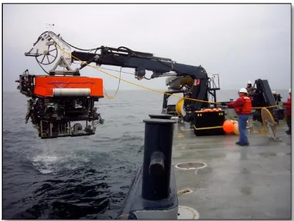
[image:19.612.88.543.143.375.2]tether may occur [1]. This paper introduce about the linear dropping load by moving the shaft downward. The shaft holds the load cover slot and moves downward to the sea water. Figure below is the experiment setup by this paper. It illustrates on how the dropping load works.
Figure 2.1 Experiment setup and the legend for discharging load [1].
6
Figure 2.2 The Stem Mounted Crane
2.3 OBSTACLE DETECTION BY SENSOR
When SV moves on the water, any obstacle lying in the path of the vehicle can give potential to damage threat. The obstacles can be avoided by the navigation plan that use the valuable information obtained to the SV. This information was provided from the inclusion data of a forward looking. Based on the paper (Martin, An, Nelson, & Smith, n.d.), sonar sensor transmits a single beam. The beam itself is deflected using phased array technique to sweep along a vertical plane [3]. The sonar sensor has following specification [4]:
Operating frequency : 650 kHz – 950 kHz
Bandwidth, Vertical : 40° at 650 kHz, 35° at 800 kHz, 30° at 950 kHz Bandwidth, Horizontal : 3.0° at 650 kHz, 2.5° at 800 kHz, 2.0 at 950 kHz
Range setting : From 5m to 100m
7
Figure 2.3 AUV with Sonar sensor and its bandwidths [6]
Another sensor that can detect the obstacle is Infrared sensor (IR). The Infrared sensor consists of one infrared LED and a pair of silicon phototransistors [5]. The phototransistor is used to detect the energy reflected by an obstacle from LED [5]. The signal returned from the sensor is dependent on the energy emitted from LED and the detectable range of the photo-transistors. The distance for the infrared sensor to detect the obstacle is less than 45 cm [5]. The infrared sensor can’t detect object above than 45 cm is because were indistinguishable due to the lack of energy detected by the phototransistors. Paper (Wu, Chen, Jiang, Yu, & Yu, 2010) states that the Infrared sensor can be classified into two categories which are:
1. Un-cooled thermal infrared sensor 2. Photon infrared sensor
8
[image:22.612.148.519.280.464.2]The Ultrasonic sensor (US) widely used to measure the distance because of its wide beam – width, sensitivity to specula surfaces. The Ultrasonic sensor can generate frequency sound waves of 310 kHz by range from 50 mm to 400 mm [5]. This sensor can calculate the time interval between sending and receiving the echo to determine the distance to an object [5]. Ultrasonic sensor produce mostly accurate representation of the object distance with various distance but it’s difficult to face the object with round shaped. They are useful under conditions of poor lightning and transparent objects. Figure below describe the area of detection object between 2 types of sensor.
Figure 2.4 Distance data from the flat surface [5]
9
2.4 ACTUATORS FOR DISCHARGING ROV
2.4.1 TYPES OF ACTUATORS
Pneumatic cylinder has several advantages which are easy maintenance, convenient assemblage, clean operating condition, higher reliability and lower cost [7]. In addition, pneumatic cylinders are light weight and can be readily installed using common compressed air supplies [8]. The pneumatic cylinder also has the limitations which are:
1. Relatively low accuracy
As pneumatic systems are powered by the force provided by compressed air, their operation is subject to the volume of the compressed air. As the volume of air may change when compressed or heated, the supply of air to the system may not be accurate, causing a decrease in the overall accuracy of the system.
2. Low loading
The cylinders of pneumatic components are not very large. Therefore, a pneumatic system cannot drive loads that are too heavy.
3. Processing required before use
Compressed air must be processed before use to ensure the absence of water vapor or dust. Otherwise, the moving parts of the pneumatic components may wear out quickly due to friction.
4. Inconsistent moving speed
10
5. Noise
Noise will be produced when compressed air is released from the pneumatic components.
The hydraulic cylinders use an incompressible fluid so the force applied at one point is transferred to another point. Based on paper (Huang & Cao, 2011), hydraulic cylinders have following superiority [9]:
Realizing step less speed regulating in large field.
Each component of fluid drive can be arranged conveniently and neatly in requirement.
Easy operating, convenient controlling and easy to realize automation and remote control.
Working substance generally uses mineral oil, and can self-lubricating compared with motion surface.
Meanwhile the disadvantages of hydraulic cylinder are stated from paper (Zhao, Chen, & Chen, 2009) are [10]:
1. Unstable hydraulic oil behavior
The compressibility of the hydraulic fluid and the working temperature change lead to oil density variation, which is an important inaccuracy sources.
2. Hydraulic system leakage
![Figure 2.1 Experiment setup and the legend for discharging load [1].](https://thumb-us.123doks.com/thumbv2/123dok_us/91037.8571/19.612.88.543.143.375/figure-experiment-setup-legend-discharging-load.webp)
![Figure 2.3 AUV with Sonar sensor and its bandwidths [6]](https://thumb-us.123doks.com/thumbv2/123dok_us/91037.8571/21.612.174.456.70.310/figure-auv-with-sonar-sensor-its-bandwidths.webp)
![Figure 2.4 Distance data from the flat surface [5]](https://thumb-us.123doks.com/thumbv2/123dok_us/91037.8571/22.612.148.519.280.464/figure-distance-data-from-the-flat-surface.webp)
