UNIVERSITI TEKNIKAL MALAYSIA MELAKA
THE EFFECT OF DIFFERENT THICKNESS MATERIAL
STACKING FOR FOUR LAYER SPOT WELDING
This report submitted in accordance with requirement of the Universiti Teknikal Malaysia Melaka (UTeM) for the Bachelor’s Degree in Mechanical Engineering
Technology (Maintenance Technology)(Hons.)
by
NUR FATIHAH BINTI MADI B071110351
920420035018
UNIVERSITI TEKNIKAL MALAYSIA MELAKA
BORANG PENGESAHAN STATUS LAPORAN PROJEK SARJANA MUDA
TAJUK: The Effect of Different Thickness Material Stacking for Four Layer Spot Welding
SESI PENGAJIAN: 2014/15 Semester 1
Saya NUR FATIHAH BNTI MADI
mengaku membenarkan Laporan PSM ini disimpan di Perpustakaan Universiti Teknikal Malaysia Melaka (UTeM) dengan syarat-syarat kegunaan seperti berikut:
1. Laporan PSM adalah hak milik Universiti Teknikal Malaysia Melaka dan penulis. 2. Perpustakaan Universiti Teknikal Malaysia Melaka dibenarkan membuat salinan
untuk tujuan pengajian sahaja dengan izin penulis.
3. Perpustakaan dibenarkan membuat salinan laporan PSM ini sebagai bahan pertukaran antara institusi pengajian tinggi.
4. **Sila tandakan ( )
SULIT
TERHAD
TIDAK TERHAD
(Mengandungi maklumat yang berdarjah keselamatan atau kepentingan Malaysia sebagaimana yang termaktub dalam AKTA RAHSIA RASMI 1972)
(Mengandungi maklumat TERHAD yang telah ditentukan oleh organisasi/badan di mana penyelidikan dijalankan)
Alamat Tetap:
Kampung Changgong, Melawi, 16300 Bachok, Kelantan.
Tarikh: 30 /1/ 2015
Disahkan oleh:
Cop Rasmi:
DECLARATION
I hereby, declared this report entitled “The Effect of Different Thickness Material Stacking for Four Layer Spot Welding” is the results of my own research except as
cited in references.
Signature : ……….
Author’s Name : Nur Fatihah Binti Madi
APPROVAL
This report is submitted to the Faculty of Engineering Technology of UTeM as a partial fulfillment of the requirements for the Bachelor’s Degree in Mechanical Engineering Technology (Maintenance Technology)(Hons.). The member of the supervisory is as follow:
i
ABSTRAK
ii
ABSTRACT
iii
DEDICATION
Highest Special Thankful Wishes to Both My Lovely Father and Mother
Madi Bin Teh &
Mek Eshah Binti Jusoh
Also
iv
ACKNOWLEDGEMENT
Firstly, millions of thankful wishes to ALLAH S.W.T because with His permissions, I am able to complete my Final Year Project report.
In preparing this paper, I have engaged with many people in helping me completing this project. First, I wish to express my sincere appreciation to my main thesis supervisor Mr Mohd Harris Fadhilah Bin Zainudin, for encouragement, guidance, advices and motivation.
Special gratitude to my father Madi Bin Teh and my mother Mek Eshah Binti Jusoh for their prayer and constant support. It is also a pleasure to thank all my siblings for encouragement from the day I started this project.
v
TABLE OF CONTENT
Abstrak i
Abstract ii
Dedication iii
Acknowledgement iv
Table of Content v
List of Tables vii
List of Figures viii
List Abbreviations, Symbols and Nomenclatures x
CHAPTER 1: INTRODUCTION
1.1 Background of The Project 1
1.2 Problem Statement 2
1.3 Objectives 6
1.4 Project Scope 6
CHAPTER 2: LITERATURE REVIEW
2.1 Resistance Welding 7
2.1.1 Projection Welding 8
2.1.2 Spot Welding 8
2.1.3 Seam Welding 9
2.1.4 Flash Welding 10
2.2 Principle of Operation for Resistance Spot Welding 10
2.3 Parameters for RSW 18
2.3.1 Squeeze Time 19
2.3.2 Weld Time 20
2.3.3 Hold Time 20
2.3.4 Weld Current 21
2.3.5 Electrode Force 21
vi
2.5 RSW Machine 24
2.5.1 Electrical Configuration of The Machine
25 2.5.2 Comparison between AC and DC RSW Machine 27
2.6 Mechanical Test 28
2.6.1 Tensile Test 27
2.6.1.1 Tensil Shear Test 28
2.6.1.2 Cross Tension Test 29
CHAPTER 3: METHODOLOGY
3.1 Introduction 31
3.2 Material Preparation 32
3.2.1 Cutting Process 33
3.2.2 Cleaning Process 35
3.3 Resistance Spot Welding 35
3.4 Mechanical Testing 37
3.4.1 Tensile-Shear Test 37
3.4.2 Procedure 39
3.5 Data Comparison 40
CHAPTER 4: RESULT & DISCUSSION
4.1 Tensile Test Result 41
4.1.1 Tensile Test Result for 2.80mm Thickness of Three Layer Spot
Welded Joint 42
4.1.2 Tensile TestResult for 2.80mm Thickness of Four Layer Spot Welded
Joint 43
4.1.3 Tensile TestResult for 3.50mm Thickness of Four Layer Spot Welded
Joint 44
4.1.4 Tensile TestResult for 4.40mm Thickness of Four Layer Spot Welded
Joint 45
4.2 Failure Mode 47
CAHPTER 5: CONCLUSIONS & FUTURE WORK
vii
5.2 Future Work 51
viii
LIST OF TABLES
3.1 Chemical Composition of the JIS G3141 SPCC Metal Sheet 32
3.2 Dimension of Specimen 35
3.3 Parameter of Spot Weld Machione 35
4.1 Result of Tensile Test for 2.80mm Thickness 42
4.2 Results of Tensile Test for 2.80mm Thickness 43
4.3 Results of Tensile Test for 3.50mm Thickness 44
4.4 Results of Tensile Test for 4.40mm Thickness 45
ix
LIST OF FIGURES
1.1 Resistance Spot Welding Machine with Workpiece 2
1.2 Distribution of impact angle (direction of impact of the impacting car) in a range of real-world side collisions (from
otte 1993 5
2.1 Projection Welding 8
2.2 Spot Welding 9
2.3 Seam Welding 9
2.4 2.5 2.6
Flash Welding
Resistance and Tig Spot Weld Comparison Schematic diagram of RSW process
10 11 11 2.7
2.8
Fundamental resistance welding machine circuits Basic period of Spot welding
12 13 2.9
2.10
Spot welding time cycle
Electrode – work – piece interface resistance – R1 and R5; resistance of the work- pieces – R2 and R4; resistance in the interface between work - pieces- R3
14 15 2.11(a) 2.11(b) 2.12’ 2.13 2.14(a) 2.14(b) 2.14(c) 2.15 2.16 2.17 2.18
(a)Manual portable spot welding gun
Portable spot welding gun on robot (automatic) Sequence of Steps in Welding Cycle
Welding Cycle
Simple Model Describing Stress Distribution at the Interface of Sheets and at Weld Nugget Periphery
Sheet Tearing in Specimen Width Direction Sheet Tearing and Nugget Pullout
Spot Welding Machine
Electrical Component of RSW Inverter Supply RSE
Schematic Diagram of AC Welder
x 2.19
2.20
Tensile Shear Test Cross-tension Specimen 29 30 3.1 3.2 3.3 3.4 3.5 3.6 3.7 3.8 4.1 4.2 4.3 4.4 4.5 4.6(a) 4.6(b) 4.7
Research Flow Chart
Foot Plate Shearing Cutting Machine Welding Sample with Label
Inverter AS-25 Weld Gun
Specimen of Sheet Metal which is Lap Joints after RSW Resistance Spot Welding Methodology
Test specimen and extensometer mounted on UTM machine (INSTRON model 5969)
Tensile Shear Test Procedure
Graph of Tensile Strain vs. Tensile Stress Sheet-2.80mm Thickness with Three Layers Spot Welded Joint
Graph of Tensile Strain vs. Tensile Stress Sheet-2.80mm Thickness with Four Layer Spot Welded Joint
Graph of tensile strain vs. tensile stress sheet-3.50mm thickness with four layer spot welded joint.
Graph Tensile Strain vs. Tensile Stress of Sheet 4.40mm-Thickness with Four Layer Spot Welded Joint
Tear at the edge of one side sheet2.80mm-thickness Tear at the edge of one side sheet 3.50mm-thickness
Initial crack formation after maximum load. The rear of the thin sheet has started folding
Interfacial failure on sheet 4.40mm-thickness
xi
LIST OF ABBREVIATIONS, SYMBOLS AND
NOMENCLATURE
AC - Alternate Current
DC - Direct Current
RSW - Resistance Spot Welding
ST - Squeeze Time
UTM - Universal Testing Machine
1
1.1 Background of The Project
Resistance spot welding (RSW) process is one of the oldest in the electrical welding processes that are mostly used in the modern manufacturing technology such as bridges, shipbuilding, home appliance and more. It also constantly used in the industry of conveyance manufacturing especially in automotive industry. In automotive industry, spot welding has been used to combine two or more plates in producing a car. Proton and Perodua are examples of local automotive industries using spot welding to fabricate their cars. For example, there are 3000-6000 spot welds in car (Luo Yi et al., 2009). Spot welding is a key technology in automotive assembly production due to fast process and can easily weld many different material combinations which are difficult or even impossible to join by other welding techniques.
In the spot welding process, two or more overlapped or stacked stamped components are welded together by applying an electric current through two contact points. The interface of the parts creates current resistance which produces heat. The application of pressure on the two metal will form a shape type that is called a “button”. The welds will be of the approximate size of the contact points and the filler metal consist of the base materials only. This process can be done by the work piece as they are held together under pressure between two electrode. This process may be performed by robotic, manually or by dedicated spot welding machine. Spot welding process
INTRODUCTION
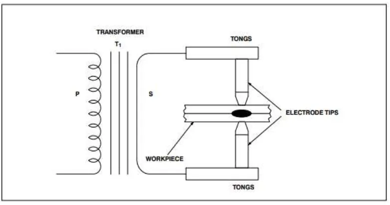
2 take only few seconds. In the Figure 1.1below, a complete secondary resistance spot welding circuit is illustrated. For clarify, the various arts of the RSW machine are stated.
Figure 1.1: Resistance Spot Welding Machine with Workpiece. (Luo Yi et al., 2009).
Spot welds are discrete weld locations that look like small circles on the assembled component due to weld that was done by spot welding process. This weld process is linear welds and they are not continuous. The weld process are usually done manually for the components in low volume while for the components in high volumes, they are usually done by using robots or dedicated weld equipment. In spot welding, there are various variable involve in the process such as current, pressure, time, human element, welders condition, surfaces condition of materials, and surface condition of electrode tips. However, some of the weld variables are difficult to manage and may cause weld problems except others such as the current, time and electrode pressure which is easy to control. Good quality of spot welding can be achieve by a good process design that minimizes the parameter during welding process.
3 introducing various combinations of different material and different thickness. The development of new, four-sheet weld sheet for use in the automotive industry represents new challenges to the industry. Joining four-sheet by spot welding can be a new trend in automotive assembly. The strength of resistant spot welded joints is important for improving auto body rigidity. By understanding the scenario of the current needed, this project was focused on investigating the mechanical properties of four-sheet resistance spot welded from different material combination.
1.2 Problem Statements
In the modern society, traffic accidents are one of the top causes of mortality (Teng et al., 2008). Based on the inspection of vehicles involved in real world crashes where at least one occupant was either hospitalized or killed ( Fildes et al., 1994).
Fildes et al., (1994) state that the most common source of injury to both front and rear occupants was the door panel and frame. Decreasing the severity of the injuries sustained by a vehicle occupant in the event of a collision involves improving the design of automobiles and their protective features and device. Thus, manufactures now working together to produce of safety devices and features into their vehicles such as airbags, energy-absorbing steering columns, side door beams, and so on.
4 describe that over 90 % of spot welds are performed by automotive industry at all over the world. It was estimated, that each body car components contains over 50 hundred spot welds. Pouranvari et al., (2013) pointed out that the failure that happen in spot welds cause the spot welds can have less strength and can lead into total destruction of manufacturing parts of car bodies. Therefore, the failure characteristics and performance of the spot welds significantly affect the durability and safety design of the vehicles. (Marashi & Pouranvari, 2012)
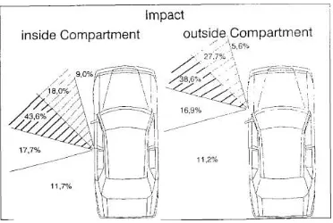
According to Marcus, Morgan et al., (1983), lateral impacts cause a big proportion of all serious and death injuries as much as 27 percentage to 30 percentage. Side impacts account for 12 percentage of total „‟harm‟‟ (Malliaris et al., 1982). Otte (1993) showed the range of directions of impact in two-car side collision as shown in Figure 1.2.
Based on the previous study on the result of side impact countermeasures, door plays the important role in side impact injuries for both near and far side impacted occupants ( Fildes et al., 1994). Thus, by improving structure of side door will help in reduce of injuries cause by side impact collision. Some manufactures have experimented with different combinations of materials and pading structure on vehicle in order to optimise injury reductions. It has been claimed that thoracic and pelvic injuries can be reduced by up to 10 percent by improving side door structure.
6
1.3 Objective
The main objective of this research is to improve car safety by improve the strength of car structure by using four layer of different thickness combination. The aim can be achieve by objective below:
I. To find out the strength of four layer welded sheets from different thickness material combinations.
II. To compare the strength of four layer welded sheet with three layer welded sheets.
1.4 Project Scope
The research is subjected to the following scope:
I. To find out the strength of four layer welded sheets by using a Universal Testing Machine (UTM) in order to analyse the tensile shear strength of welded sheets.
II. Using four of different thickness of metal sheet as the welding material. III. The total thickness of each sample is 2.80mm, 3.50mm, and 4.40mm.
IV. Using metal sheet (JIS G3141 SPCC-1B) , (JIS G3141 SPCC-SD) and (JIS G3141 SPCC-SB)
7
2.1 Resistance Welding
Resistance spot welding process was invented in 1877 by Professor Elihu Thomson and has been widely used since then in manufacturing industry, especially in the automobile and air craft industries (Saleem, 2012). In the spot welding
process, an electric current is passed through the parts being welded together, by using highly conductive electrode. A pressure is exerted during the process so as to hold the parts to be welded. The weld is made by a combination of heat, pressure, and time. In order to make a good welding joint, sufficient heat must be produced at the surface of the metal plates which are to be joined together. Current, force and time must be properly related in order to obtain a good weld.
The resistance welding process can be classified into • Projection welding
• Spot welding • Seam welding • Flash butt welding
LITERATURE REVIEW
8
2.1.1 Projection Welding
[image:23.595.258.414.309.432.2]It is a type of resistance welding process in which specially designed projections, shown in Figure 2.1 exist in one part. The simultaneous welding of several projections is possible during one weld. This projection, act as a current concentrator for the welding process and these projections are the high points during the welding cycles, that make the first contact. The main advantage of the resistance projection welding is the speed and versatility to be automated (Saleem, 2012). With projection welding, several welds can be conducted simultaneously.
Figure 2.1: Projection Welding
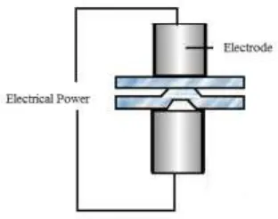
2.1.2 Spot Welding
9 desired temperature. If the heat produced is less than this temperature then the result will be a low strength weld.
Figure 2.2: Spot Welding
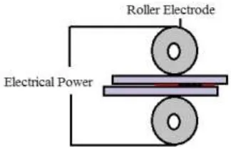
2.1.3 Seam Welding
In seam welding the electrodes which are used for the welding, are in the form of rollers as shown in Figure 2.3. The electrical current is passed through the roller shaped electrodes, which produce heat at the interface of the sheets to be joined. A seam welding process produces a series of nuggets at the interface of the work pieces.
[image:24.595.218.380.545.650.2]