ZF DFE TRANSCEIVER DESIGN FOR MIMO RELAY SYSTEMS WITH DIRECT
SOURCE-DESTINATION LINK
Andrew P. Millar, Stephan Weiss, and Robert W. Stewart
Department of Electronic & Electrical Engineering University of Strathclyde
Glasgow, G1 1XW, Scotland, UK
{andrew.millar, stephan, r.stewart}@eee.strath.ac.uk
ABSTRACT
In this paper we consider a non-linear transceiver design for non-regenerative multiple-input multiple-output (MIMO) re-lay networks where a direct link exists between the source and destination. Our system utilises linear processors at the source and relay as well as a zero-forcing (ZF) decision feed-back equaliser (DFE) at the receiver. Under the assumption that full channel state information (CSI) is available the pre-coding and equaliser matrices are designed to minimise the arithmetic mean square error (MSE) whilst meeting transmit power constraints at the source and relay. The source, re-lay, and destination processors are provided in closed form solution. In the absence of the direct link our design partic-ularises to a previous ZF DFE solution and as such can be viewed as a generalisation of an existing work. We demon-strate the effectiveness of the proposed solution through sim-ulation and show that it outperforms existing techniques in terms of bit error ratio (BER).
1. INTRODUCTION
The use of relaying nodes to forward data from a source to destination offers spatial diversity in a communication sys-tem which can extend network coverage, increase channel capacity, and improve link reliability [1], [2], [3]. When each node in the network is equipped with multiple antennas the system is referred to as a MIMO relay system. MIMO relay-ing has gained significant attention from researchers lately and are considered an integral component in the design of next generation wireless networks.
MIMO relay transceivers are generally categorised as either decode forward (DF) or amplify forward (AF) [1], which are also commonly known as regenerative and non-regenerative respectively. In the case of non-regenerative relay-ing the relay node decodes the received signal, re-encodes the data bits, and then forwards to the next node in the net-work. In non-regenerative protocols the relay simply trans-mits an amplified version of the received signal to the subse-quent node in the system. It is well known performing linear precoding at the relay can significantly enhance performance when compared to the conventional AF protocol [2], [4], [5]. Linear transceiver designs have been well studied for non-regenerative MIMO relaying. In [4] the optimal relay precoder that minimises the arithmetic MSE is derived under the assumption that the source precoder is a scaled identity matrix. A unified framework, based on majorisation theory, is presented in [5] for multi-carrier non-regenerative MIMO relays where the optimal source and relay precoders are de-rived for Schur convex and Schur concave objective func-tions. It is shown that for Schur concave objective functions
the optimal source and relay processors diagonalise the MSE matrix and subsequently the overall communication system is converted to a set of single-input single-output (SISO) sub-systems. For the case of Schur convex objective functions the optimal processors result in a MSE matrix with non-diagonal structure and the system is only diagonalised up to a specific rotation of the transmit and receive data symbols.
Non-linear techniques have also been considered for two-hop MIMO relay systems. The solution for the source and relay precoders when a DFE is utilised at the destination was investigated in [6]. In [7] minimum MSE processors were de-rived for a non-regenerative MIMO relay network with Tom-linson Harashima precoding employed at the source.
The works in [4], [5], [6], and [7] all assumed that the destination did not use any information received directly from the source. The direct source-destination link provides extra spatial diversity in the system and can lead to further benefits in performance. The authors in [8] investigate the joint design of linear precoders to minimise the arithmetic MSE when the direct link is included. It is shown that with the inclusion of the direct link the optimisation problem is very complicated and a direct minimisation of the MSE is difficult. As such the authors propose to minimise an upper bound on the MSE which, although leads to a suboptimal solution, significantly simplifies the design process.
In this work we focus on the design of linear processors when a ZF DFE is employed at the destination and a direct path exists between the source and destination antennas. We assume that each node in the network has full CSI and derive processors to minimise the arithmetic MSE. The remainder of the paper is organised as follows: In section 2 we introduce the signal model for the system under consideration. Section 3 presents the transceiver design and a numerical example is provided in section 4. Finaly conclusions are drawn in 5.
Notation: We conform to the standard notation where vectors and matrices are denoted by lower and upper case bold font respectively. The sets of real and complex numbers areRandC, which in the case of vector and matrix quantities
indicate dimensions by means of a superscript. The operators
E{·}, tr{·},(·)H,(·)−1,(·)†, and|·| denote the expectation,
trace, hermitian transpose, inverse, pseudo-inverse, and de-terminant respectively. IM is theM×M identity matrix and 0N×Mis a matrix of dimensionN×Mwith zero entries. The element in theithrow and jthcolumn of matrixAis denoted asai j and theith element of vectorais denoted asai. Ma-trix rank is noted byrank(·)anddiag{a1,a2, ...,aN}denotes a diagonal matrix with diagonal entries{a1,a2, ...,aN}. The operators min(a,b) andmax(a,b)return the minimum and maximum values ofaandband we define[x]+,max(x,0).
vs[n]
r[n]
vr[n+1]
yr[n+1]
Hr G
vd[n]
Hd
B
˜
x[n+1]
z[n+1]
yd[n]
ˆ
x[n+1]
W F
x[n]
[image:2.595.86.508.70.181.2]Hs
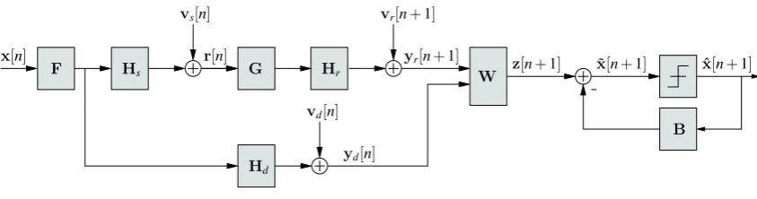
Figure 1: DFE signal model for a two-hop MIMO relay system with direct source-destination link.
2. SYSTEM MODEL
We consider transmission ofNsdata streams over a two-hop MIMO relay system where the source, relay, and destina-tion haveNs,Nr, andNd antennas respectively and a direct link exists between the source and destination. To ensureNs data streams can be transmitted across the network we as-sume thatNs≤min(Nr,Nd). For the purposes of interference cancellation we admit linear processors in each stage of the network and employ a DFE at the receiver. This configura-tion is shown in Figure 1.
Due to half-duplex relaying the transmission of data from source to destination is carried out over two seper-ate time-slots. In the first phase the data symbols x[n]∈ CNs, which are assumed to be uncorrelated with covariance E
x[n]x[n]H =I
Ns, are transmitted to both the relay and destination. The relay receivesr[n]∈CNr given by
r[n] =HsFx[n] +vs[n] (1)
whereHs∈CNr×Ns is the source-relay channel,F∈CNs×Ns is the linear source precoder, and vs[n]∈CNr is an addi-tive white Gaussian noise (AWGN) vector with covariance
Rvsvs =E
vs[n]vsH[n] =σv2sINr. The signal yd[n]∈C Nd received at the destination in the first time-slot is
yd[n] =HdFx[n] +vd[n] (2)
whereHd∈CNd×Ns is the direct source-destination channel andvd[n]∈CNd is an AWGN vector with covariance matrix Rvdvd =E
vd[n]vHd[n] =σv2dINd.
In the second phase of transmission the relay processes the signal r[n] and transmits across the relay-destination channel Hr ∈CNd×Nr resulting in the data received at the destination in the second phaseyr[n+1]∈CNd being
yr[n+1] =HrGr[n] +vr[n+1] (3)
whereG∈CNr×Nr andH
r∈CNd×Nr are the relay precoder and relay-destination channel respectively and the noise vec-torvr[n+1]∈CNr×Nd contains AWGN samples with covari-anceRvrvr=E
vr[n+1]vH
r[n+1] =σv2rINd.
The data received at the destination over two consecutive time-slots, given in (2) and (3), is processed by the linear equaliserW∈CNs×2Nd resulting in
z[n+1] =WHFx[n] +Wv[n+1] (4)
where for notational convenience we define
H,
Hd HrGHs
,v[n+1],
vd[n] HrGvs[n] +vr[n+1]
.
(5)
HereH∈C2Nd×Ns is the effective MIMO channel between the source and destination antennas andv[n+1]∈C2Ndis the equivalent noise vector at the equaliser input with covariance matrixRvv=Ev[n+1]vH[n+1] given by
Rvv=
σ2
vdINd 0Nd×Nd 0Nd×Nd HrGG
HHH
rσv2s+σ
2
vrINd
. (6)
After processing byW, successive interference cancel-lation is performed by a strictly upper right triangular matrix
B∈CNs×Ns. The data estimates in ˆx[n+1]∈CNs are recur-sively computed according to [9]
ˆ
xi[n+1] =C "
zi[n+1]− Ns
∑
j=i+1bi jxˆj[n+1] #
(7)
for j=Ns,Ns−1, . . . ,1. The operatorC[.]signifies a map-ping to the nearest constellation point of the transmitted sym-bols. The operation in (7) is equivalent to successively mak-ing decisions [10] on
˜
x[n+1] =WHFx[n] +Wv[n+1]−Bxˆ[n+1]. (8)
The error between the input to the decision device and the transmitted symbols is defined ase[n+1],x˜[n+1]−x[n]
which using (8) results in
e[n+1] = (WHF−U)x[n] +Wv[n+1] (9)
where we have used the standard assumption of correct past decisions [9], [10], and we defineU,B+INsas a unit diag-onal upper right triangular matrix. Using the error signal in (9) the error covariance matrixRee=E
e[n+1]eH[n+1]
can be computed as
Ree= (WHF−U) (WHF−U)H+WRvvWH. (10)
The transceiver in this paper aims to minimise the arithmetic MSE, which is simply given by tr{Ree}/Ns, whilst meeting certain system constraints.
3. TRANSCEIVER DESIGN
3.1 Optimal ZF Equaliser
The ZF condition ensures a perfect reconstruction of the transmit symbols in the absence of noise and imposes the following constraint on the equaliser matrixW
WHF=U (11)
which upon substituting in (10) results in the error covariance matrixReereducing to
Ree=WRvvWH. (12)
It is well known [10] that, for a givenU,H,F, andRvv, the optimal solution forWthat minimises (12) and satisfies the condition in (11) is provided by
W=UR−vv1/2HF †
R−vv1/2. (13)
SinceNs≤Nd the productRvv−1/2HF∈C2Nd×Ns has more rows than columns and as such the pseudo-inverse [11] is given by(R−vv1/2HF)†= (FHHHR−vv1HF)−1FHHHR
−1/2
vv . Substituting (13) in (12) we arrive at the MSE matrix
Ree=U FHHHR−vv1HF −1
UH (14)
where we note that the error covariance is now no longer a function of the equaliser matrixW.
3.2 Constrained Optimisation Problem
As previously mentioned the transceiver design in this paper aims to minimise the arithmetic MSE. However, as in [6], [7], and [10], we propose to minimise the geometric MSE, which lower bounds the arithmetic MSE, and then suitably contruct processors such that the arithmetic MSE achieves the minimised lower bound.
The relationship between the arithmetic and geometric MSE is a simple consequence of the arithmetic-geometric mean inequality [11] which states that for a positive semi-definite matrixA∈CN×N we have the inequality|A|1/N ≤ tr{A}/N where equality is achieved if, and only if, A=
αINfor anyα≥0. Applying the arithmetic-geometric mean inequality to (14) we obtain the following bounds
|FHHHR−vv1HF)|−1/Ns ≤tr
U(FHHHRvv−1HF)−1UH /N
s (15)
where we have used the facts that|A−1|=|A|−1,|AB|=
|A||B|for square matrices AandB, and|U|=|UH|=1
sinceUis a unit diagonal triangular matrix. Using the lower bound in (15) as the objective function and considering the source and relay power constraints we arrive at
min
F,G |(F
HHHR−1
vvHF)|−1/Ns (16)
s.t. tr
FFH =Ps (17)
tr
G(HsFFHHHs +σv2sINr)G
H =P
r (18)
Here (17) and (18) are the source and relay power constraints andPsandPr are the available power budgets. We note that the optimisation problem in (16), (17), and (18) is the same as that for the ZF DFE design in [6]. However, as will be seen, the solution differs significantly due to the inclusion of the direct source-destination link.
3.3 Precoder and Feedback Processors
We now focus on the design of the source and relay pre-coders,FandG, as the solution to (16), (17), and (18) as well as the feedback matrixB.
3.3.1 Source Precoder Structure
For a given relay precoderGthat satisfies the relay power constraint in (18) we introduce the decomposition
HHR−vv1H=VhΛhVhH (19)
whereVh∈CNs×Ns is a unitary matrix and the diagonal ma-trixΛh=diag
λh1,λh2, . . . ,λhNs contains the non-zero sin-gular values ofHHR−vv1H. We assume here that the matrix
HHR−vv1His full rank i.e.rank
HHR−vv1H =Ns.
Using the Hadamard determinant inequality [11] we can state from (16) and using the decomposition in (19) that
|FHHHR−1
vvHF|−1/Ns≥ Ns
∏
i=1γ2
iλhi −1/Ns
(20)
where the lower bound is achieved with any processor F
given by F=VhΓΨ where Γ=diag{γ1,γ2, . . . ,γNs} and Ψ∈CNs×Ns is an arbitrary unitary matrix. The elements of the power allocation matrixΓcan be found by substituting
F=VhΓΨin (16) and (17) and solving
min γi
Ns
∏
i=1γ2
iλhi −1/Ns
(21)
s.t. Ns
∑
i=1γ2
i =Ps, γi2≥0, ∀i. (22)
This is a standard convex optimisation problem and the so-lution can be found using the Karush-Kuhn-Tucker (KKT) method [12] and is given by γi =
p
Ps/Ns, ∀i. We can thus state that, for any relay precoderGthat satisfies (18), the source precoder that minimises (16) and satisfies (17) is given by
F=p
Ps/NsVhΨ (23)
whereΨis a unitary matrix yet to be determined.
3.3.2 Relay Precoder Structure
Having established the structure of the source precoderFwe now focus on computing the relay processorG. We firstly note that using the definitions forHandRvv in (5) and (6) and the source precoder in (23) we can expand the determi-nant in (16) as
|FHHHR−1
vvHF|−1/Ns= (Ns/Ps)|D+XYZ|−1/Ns (24) where for convenience we define matricesD,HHdR−v1
dvdHd, X,HH
sGHHHr, Y, HrGGHHHrσv2s+σ
2
vrINr −1
, and
Z,HrGHs. We note here that when the direct link is negligible (24) particularises to the objective function for the ZF design in [6]. As such our design is a generalisation of the ZF DFE transceiver in [6] to include the direct source-destination link.
The relay precoder G must be designed such that
(Ns/Ps)|D|−1/Ns|INs+D −1/2HH
sGHHHr HrGGHHHrσv2s+σ
2
vrINd −1
HrGHsD−1/2|−1/Ns ≥(Ns/Ps)
Ns
∏
i=1λ−1/Ns di
Ns
∏
i=1
1+λ2
tiφ
2
iλr2i φ
2
iλr2iσ
2
vs+σ
2
vr
−1−1/Ns
(28)
(18) is satisfied. From the Hadamard determinant inequality we can state that the determinant is minimised if the matrix
D+XYZ is diagonalised by the precoder G. It is clear that this diagonalisation cannot be directly conducted since
Dis not a function ofG. However we note that by using
D+XYZ=D1/2(INs+D−1/2XYZD−1/2)D1/2 we can write the optimisation for the relay precoder in (16)-(18) as
min
G (Ns/Ps)|D|
−1/Ns|I Ns+D
−1/2XYZD−1/2|−1/Ns (25)
s.t. tr
G(HsFFHHHs +σv2sINr)G
H =P
r (26)
where we note that the source power constraint has been omitted from the optimisation problem because it is guar-anteed to hold with the precoderFgiven in (23).
Before calculating the relay precoderG as the solution to (25) and (26) we firstly introduce the following singular value decompositions
D=UdΛdVdH, HsD−1/2=UtΛtVtH, Hr=UrΛrVHr (27) where Ud ∈CNs×Ns, V
d ∈ CNs×Ns, Ut ∈ CNr×Ns, Vt ∈ CNs×Ns,U
r∈CNd×Nr, andVr∈CNr×Nr are all unitary ma-trices. The matrices Λd=diag
λd1,λd2, . . . ,λdNs , Λt = diagλt1,λt2, . . . ,λtNs and Λr = diag
λr1,λr2, . . . ,λrNr are diagonal matrices containing the singular values ofD,
HsD−1/2, andHrrespectively.
Applying the Hadamard determinant inequality to (25), and using the definitions forX,Y, andZ, as well as the sin-gular value decompositions in (27), we can state the inequal-ity shown in (28) at the top of the page. The lower bound in (28) is achieved when the relay precoder is of the form
G=V¯rΦUHt (29)
where ¯Vr∈CNr×Nscontains the leftmostNscolumns ofVr, Φ=diag{φ1,φ2, . . . ,φNs}, andUt was defined in (27). The elements of the diagonal matrixΦcan be found by minimis-ing the objective function in (28) subject to the power con-straint (26). The problem can be stated as
min φi
Ns
∏
i=1
1+λt2iφ
2
iλr2i φ
2
iλr2iσ
2
vs+σ
2
vr
−1−1/Ns (30)
s.t. Ns
∑
i=1φ2
i pii=Pr, φi2≥0, ∀i. (31)
where pii is the element in the ith row and ith column of the matrix P,UH
t Us (Ps/Ns)Λ2s+σv2sINs
UH
sUt. Here Us∈CNr×Ns andΛs=diag
λs1,λs2, . . . ,λsNs result from the singular value decompositionHs=UsΛsVHs. We also
note that the term(Ns/Ps) Ns
∏
i=1
λ−1/Ns
di has been omitted from
(30) since it is a constant and has no effect on optimisation of the variablesφi. The solution to the optimisation problem can be found using the KKT conditions of optimality to be
φ2
i =
−bi+
q
b2i−4aici 2ai
+
(32)
where we define the variables
ai,λr4iσ
2
vs(λ
2
ti+σ
2
vs), bi,λ
2
riσ
2
vr(λ
2
ti+2σ
2
vs), ci,
!
σv4r− µλ2
tiλ
2
riσ
2
vr pii
%
. (33)
Here the parameterµmust be calculated to satisfy (31). The remaining task is to calculate the feedback matrix
B and the unitary source matrix Ψ such that (15) holds with equality and the arithmetic MSE achieves the minimised lower bound in (28). With the decomposition in (19) and the source precoder in (23) we calculateBandΨsimilar to [10] by performing the following geometric mean decomposition
p
Ps/NsΛ1/2h =QUΨ¯
H
(34)
whereQ∈CNs×Nsis an orthogonal matrix and ¯U,β−1/2U is an upper right triangular matrix with diagonal elements β−1/2. Here we defineβto be the lower MSE bound in (28). The feedback matrixBis now given byB=β1/2U¯ −I
Ns. 4. SIMULATION RESULTS
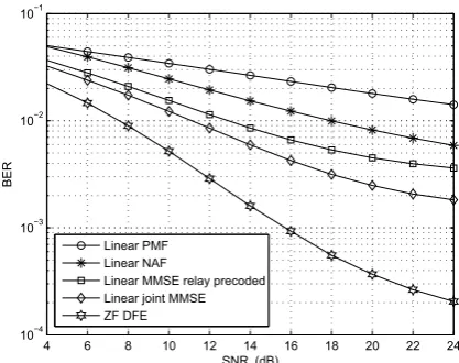
We assess the BER performance of the proposed system through simulations and compare it to existing linear tech-niques. We compare our design to the Naive AF (NAF), Pseudo-Matched Filter (PMF), optimal MMSE relay pre-coded design in [4], and the joint MMSE design in [8].
All benchmark systems use the optimal MMSE receiver, that takes the direct source-destination link into consid-eration, given by W = FHHH(HFFHHH +R
vv)−1.
Both the NAF and PMF algorithms employ
F = p
Ps/NsINs at the source. The relay pre-coders for the PMF and NAF designs are given by
G = qPr/trHrHHHs(HsFFHHHs +σv2sINr)HsHr HHrHHs andG=qPr/trHsFFHHsHσs2+σv2sINr INr respectively. The precoders for the optimal MMSE relay precoded system and joint MMSE design are given in [4] and [8] respectively. We assume the channel matrices contain complex Gaus-sian entries with zero mean and unit variance and the sym-bols from the source antennas are drawn from QPSK con-stellations. We define the signal-noise ratio (SNR) for the source-relay, relay-destination, and source-destination stages as SNRs,Ps/σv2s, SNRr,Pr/σ
2
vr, and SNRd,Ps/σ
2
4 6 8 10 12 14 10−6
10−5 10−4 10−3 10−2 10−1 100
SNR (dB)
BER
Linear PMF Linear NAF
[image:5.595.317.526.80.245.2]Linear MMSE relay precoded Linear joint MMSE ZF DFE
Figure 2: BER versus SNR forNs=Nr=Nd=4.
In the first simulation we consider transmission of data streams over a network withNs=Nr=Nd=4 antennas at the source, relay, and destination. We set SNR=SNRs = SNRr=SNRdand compare the BER performance of the pro-posed and benchmark designs for varying SNR shown in Fig-ure 2. In the second scenario we considerNs=Nr=Nd=3 and set SNRs=15 dB and SNRd=5 dB. Figure 3 shows the BER performance of all designs for varying SNRr. All simulation results obtained were averaged over 1000 chan-nel realisations. It is clear that the proposed ZF DFE design offers a significant increase in performance in terms of BER compared to the linear benchmark systems.
5. CONCLUSIONS
In this paper we considered a non-linear transceiver design for AF MIMO relay networks where a direct link exists be-tween the source and destination. Linear processors were utilised in each layer of the network and a decision feedback device at the receiver. The processors were designed to min-imise the arithmetic MSE under the ZF condition and power constraints at the source and relay. Our design generalises an existing ZF DFE for the case of a direct source-destination link. Simulations demonstrate that the proposed design out-performs existing linear techniques in terms of BER.
Acknowledgement
This work was supported by a Motorola University Research Grant and a University of Strathclyde Scholarship.
REFERENCES
[1] J.N. Laneman, D.N.C. Tse, and G.W. Wornell, “Coop-erative diversity in wireless networks: Efficient proto-cols and outage behaviour,” IEEE Trans. Information Theory, vol. 50, pp. 3062 – 3080, Dec. 2004.
[2] X. Tang and Y. Hua, “Optimal design of non-regenerative MIMO wireless relays,” IEEE Trans. Wireless Communications, vol. 6, pp. 1398 – 1407, Apr. 2007.
4 6 8 10 12 14 16 18 20 22 24 10−4
10−3 10−2 10−1
SNRr (dB)
BER
Linear PMF Linear NAF
[image:5.595.63.270.81.246.2]Linear MMSE relay precoded Linear joint MMSE ZF DFE
Figure 3: BER versus SNRr forNs=Nr=Nd=3, SNRs= 15 dB and SNRd=5 dB
[3] B. Wang, J. Zhang, and A. Host-Madsen, “On the ca-pacity of mimo relay channels,” IEEE Trans. Informa-tion Theory, vol. 51, pp. 29 – 43, Jan. 2005.
[4] W. Guan and H. Luo, “Joint MMSE transceiver design in non-regenerative MIMO relay systems,”IEEE Com-munications Letters, vol. 12, pp. 517 – 519, Jul. 2008. [5] Y. Rong, X. Tang, and Y. Ha, “A unified framework for
optimizing linear non-regenerative multicarrier MIMO relay communication systems,” IEEE Trans. Signal Processing, vol. 57, pp. 4837 – 4851, Dec. 2009. [6] A.P. Millar and S. Weiss, “Transceiver design for
non-regenerative MIMO relay systems with decision feed-back detection,”18th European Signal Processing Con-ference, Aalborg, Denmark, Aug. 2010, pp 402 - 406. [7] A.P. Millar, S. Weiss, and R.W. Stewart,
“Tomlin-son harashima precoding design for non-regenerative MIMO relay networks,” accepted for publication in 73rd IEEE Vehicular Technology Conference, Bu-dapest, Hungary, May. 2011.
[8] F.S. Tseng and W.R. Wu, “Linear MMSE transceiver design in amplify-and-forward MIMO relay systems,” IEEE Trans. Vehicular Technology, vol. 5, pp. 754 – 765, Feb. 2010.
[9] Y. Jiang, J. Li, and W.W. Hager, “Joint transceiver de-sign for MIMO communications using geometric mean decomposition,” IEEE Trans. Signal Processing, vol. 53, pp. 3791 – 3801, Oct. 2005.
[10] F. Xu, T.N. Davidson, J.K. Zhang, and K.M. Wong, “Design of block transceivers with decision feedback detection,”IEEE Trans. Signal Processing, vol. 54, pp. 965 – 978, Mar. 2006.
[11] R.A. Horn and C.R. Johnson, Matrix Analysis, Cam-bridge University Press, CamCam-bridge, UK, 1985. [12] S. Boyd and L. Vandenberghe, Convex Optimisation,