by
Tan Loc Le, B.E.E., M.Tech., C.P.Eng., M.I.E.Aust.
Department of Electrical and Electronic Engineering
Submitted in fulfilment of the requirements
for the ilegree of
Doctor of Philosophy
University of Tasmania
Australia
December 1996
fJ
Date
4/1/21/qq_c
Statement of Originality
I declare that this thesis reports my own original work, that no part of the thesis has been accepted or presented for the award of any degree or diploma by any university, and that to the best of my knowledge the thesis contains no material previously published or written by another person except where due reference is given by direct credit in the text or in the bibliography.
Tan Loc Le
Authority of access
This thesis may be made available for loan. Copying of any part of this thesis is prohibited for two years from the date this statement was signed; after that time limited copying is permitted in accordance with the Copyright Act 1968.
Abstract
In power system operation, steady state security control is employed to provide continuous supply to customers and avoid damage to power system plant. The steady state security control includes detection and alleviation of transmission equipment overloads and bus voltage violations.
The three main functions of the security control, ie. security monitoring, contingency analysis and control action analysis, can be performed by an experienced system operator with the use of conventional optimisation methods. However, such methods require large computation time and rely on mathematical models and sophisticated programming techniques. They can only cover the analytical part of solutions, leaving the burdensome task of making numerous judgements to the system operator. These methods may not be used for real-time control of large power systems; in particular, under emergency and abnormal operating conditions when significant human expertise is required but due to emotional stress is not readily available. Thus, there is a need for new methods and tools such as decision-support systems, to improve the computational speed and assist operators in making prompt and correct decisions on control actions under emergency and abnormal conditions.
During the last decade the computational approach to artificial intelligence (AI) has undergone a significant evolution. Results obtained from the international surveys on AI applications in power systems show that an interest in applications of Al to power system problems is growing strongly. Al is a promising technology that will be able to fill the gap between human capabilities and difficulties involved in the daily operation and planning of modern power systems.
The work presented in this thesis addresses the aspects of Al applications to steady state security control in power systems. This research focuses on two major
incorporate operator knowledge, provide an interactive-mode interface to users, and improve the computational speed. Three decision-support systems have been developed:
• an intelligent system for determination of short-time thermal ratings and permissible overload duration of transmission lines using the rule-based expert system and artificial neural network.
• a prototype expert system for transmission line overload alleviation using database, rule-based, and sensitivity tree approaches.
• a prototype expert system for voltage control and reactive power compensation using rule-based and sensitivity tree approaches.
The following methods have been proposed and implemented in the development of the above decision-support systems:
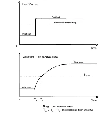
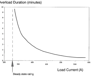
• Determination of permissible overload duration of transmission lines based on the short-time thermal rating.
• Estimation of instantaneous solar radiation employed in the determination of thermal rating of transmission lines using artificial neural network and regression techniques.
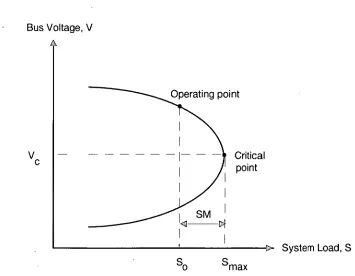
• Estimation of the distance to a voltage collapse using the stability margin analysis.
• Automatic allocation of static and dynamic reactive power compensation to improve solution of voltage security and stability control.
• Reduction of the computation time for voltage and reactive power control using the "three-tier" network equivalencing technique.
decision-support systems provide fast and correct solutions with advice on control actions expressed in the natural language form. Therefore, the intelligent systems developed can be effectively applied to assist operators in the detection and alleviation of line overload and bus voltage violation problems in power systems.
Nineteen refereed technical papers have been published including three in international scientific journals. The research results have been applied to current practice in the Hydro-Electric Commission of Tasmania for planning and operation studies.
Firstly, I am highly indebted to my supervisor, Dr. Michael Negnivitsky, for his valuable suggestions, guidance, discussion and encouragement throughout the project. A grateful acknowledgement to Professor D. Thong Nguyen, Head of the Electrical and Electronic Engineering Department, University of Tasmania, for providing me with an opportunity to attempt this higher degree. Thanks also go to Dr. Marian Piekutowski, Mr. Kelvin Prendergast, Mr. Henk Kremer, Mr. Alf Clark, and Mr. Lyndsay Watt of the Hydro-Electric Commission in Tasmania for their support. I would like to record appreciation to the University of Tasmania for providing the opportunity of a scholarship; and to the Hydro-Electric Commission and the Electricity Supply Association of Australia for granting financial assistance and support during my postgraduate study.
Lastly, I would like to thank my wife, Wen Jun, for her love, understanding and encouragement throughout my studies.
Contents
Abstract iv
Acknowledgements vii
Contents viii
Preface xi
Glossary xvi
List of figures and tables xviii
1. Introduction 1-9
1.1. States of operation in power systems 2
1.2. Security control functions 5
1.3. Natural problems of security control 7
1.4. General principles and research objective 8
2. Steady State Security Control Analysis 10- I 6
via Conventional Methods
2.1. Tools for steady state security control analysis 10
2.2. Conventional methods with disadvantages 11
2.3. Recognised needs for artificial intelligence application 14
3. Background of Artificial Intelligence Techniques 17-53
3.1. Expert systems 19
3.1.1. Architecture of an expert system 21
3.1.2. Advantages and limitations 24
3.2. Neural networks 25
3.2.1. Neural network models 26
3.2.2. Advantages and limitations 33
3.3. Fuzzy logic 35
3.3.1. Fuzzy set theory and fuzzy system architecture 35
3.3.2. Advantages and limitations 50
3.4. Future evolution of artificial intelligence 51
55
4.3. Al applications in contingency analysis 58
4.4. Al applications in control action analysis 60
5. Methods for Determination of Voltage Security Limit and 64-77
Permissible Duration of Transmission Equipment Overload
5.1. Determination of stability margin for 65
voltage security assessment
5.2. Determination of permissible duration for a 67
transmission line overload
5.3. Determination of permissible duration for a 70
transformer overload
Appendix A Determination of thermal rating of transmission lines 73
Appendix B Procedure for predicting conductor temperature rise 76
6. Application of Artificial Intelligence to Short-Time 78-115
Loading Capability Assessment of Transmission lines
6.1. Effect of cloud and ground reflection on the 80
determination of solar heat gain
6.2. Prediction of instantaneous solar radiation using 82
artificial neural network approach
6.3. An intelligent system for short-time loading 86
capability assessment of transmission lines
6.4. Intelligent system evaluation 96
6.5. Case studies 98
6.6. Discussion and summary 102
Appendix C Prediction of solar radiation using conventional methods 105
7. Application of an Expert System for Overload Alleviation 116-141
7.1. General principles of overload alleviation 117
7.1.1. Selection of remedial actions 118
7.1.2. Alleviation of overloads using the sensitivity method 119
7.2. Expert system development 121
7.3. Case studies 131
7.4. Discussion and summary 141
8. Application of an Expert System for 142-165
Voltage Control and Reactive Power Compensation
8.1. General principles of voltage and VAR control 143
8.1.1. Selection of remedial actions 144
8.1.2. Sensitivity tree method 144
8.2. Expert system development 147
8.3. Case studies 154
8.4. Discussion and summary 163
9. Application of the Netwotk Equivalencing Technique 166-190
in Voltage and Reactive Power Control
9.1. Problem formulation 167
9.2. Construction of the steady state equivalent network 168
9.2.1. Procedure for construction of equivalent network 169
9.2.2. Derivation of the internal subsystem 170
9.2.3. Derivation of the external equivalents 171
9.2.4. Selection of the effective controllers in the external areas 173
9.3. Case studies 173
9.4. Discussion and summary 183
Appendix D Methods of Adding and Removing Buses and Lines 186
10. Methods for Optimal Allocation of Reactive 191-212
Power Compensation in Power Systems
10.1. The need for reactive power compensation 192
10.2. Static VAR compensation 194
10.2.1. Allocation of static VAR compensation 194
10.2.2. Case studies 196
10.2.3. Discussion 200
10.3. Dynamic VAR compensation 201
10.3.1. Allocation of dynamic VAR compensation 201
10.3.2. Case studies 203
10.3.3. Discussion 210
10.4. Summary 211
11. Summary and Future Extensions 213-217
11.1. Results and contributions 213
11.2. Future extensions 216
11.3. Conclusion 217
References 218-242
Artificial intelligence (Al) is not a new topic and its concept was introduced a long time ago, however, the problem-solving potential of AI has been exploited only recently. During the last decade, AI techniques have captured interest in many fields of engineering, particularly in electric power engineering, and this trend is likely to be continued.
This thesis presents the candidate's work in an attempt to apply Al state-of-the-art including expert system, neural networks and fuzzy logic techniques in the development of decision-support systems to assist system operators to perform the steady state security control in power system operation. The goal of the development of the decision-support systems is the detection and alleviation of transmission equipment overloads and bus voltage violations in power systems in emergency and abnormal operating conditions.
As indicated in the contents, the thesis consists of eleven chapters. The first chapter describes the states of operation, functions and natural problems of the steady state security control in power systems. This chapter also includes a description of the general principles and objectives of the candidate's research in this field. Chapter 2 describes the conventional methods employed in the steady state security control analysis and their disadvantages, and discusses reasons for Al applications in this area. Chapters 3 and 4 provide a background on the Al techniques, and an investigation into the various applications of these techniques in power system security control.
Chapter 5 describes the use of the stability margin and short-time thermal rating approaches to measure the distance to a voltage collapse and to determine the limiting time allowed to overload transmission equipment for a current operating condition. These approaches have been implemented by the candidate in
conjunction with the Al techniques. Chapter 6 describes the application of an intelligent system combining an expert system and artificial neural networks for evaluation of short-time thermal rating and permissible overload duration of transmission lines. Chapter 7 describes the application of an expert system for the detection and alleviation of transmission equipment overloads in power systems.
Chapters 8 describes the application of an expert system to identify and solve voltage violation problems in power systems. In order to improve the computational performance of the voltage and VAR control in large-scale power systems, a new approach based on the joint application of the steady state network equivalencing and expert system techniques is introduced and described in Chapter 9.
In addition, Chapter 10 presents different methods used in system planning studies for the optimal allocation of static and dynamic reactive compensation to provide automatic and continuous voltage control, and to improve the damping of power system oscillations following any severe disturbance. The problems addressed in this chapter may be considered as an additional part of the research because they are related to power system planning, rather than to the system operational. Finally, Chapter 11 provides a summary of the contributions made by the candidate and the major results of this work, and suggests some future developments.
The thesis contains many numerical examples and practical applications to illustrate the concepts presented through the use of the simple test systems as well as the large-scale Tasmanian Hydro-Electric power system. It is hoped that the thesis will be of interest and value to the readers whose task is the planning and operation of power systems.
This research resulted in a number of journal and conference publications listed below:
Journal Publications
[I ]
T.L.Le, M.Negnevitsky and M.Piekutowski, "Expert system application for voltage control and VAR compensation", International Journal on Engineering Intelligent Systems,Vol. 3, No. 2, June 1995, pp. 79-85.[2] T.L.Le, M.Negnevitsky and M.Piekutowski, "Expert system application for • the loading capability assessment of transmission lines", International Journal of IEEE Transaction on Power Systems, Vol. 10, No. 4, Nov. 1995, pp.1805-1812.
[3] T.L.Le and M.Negnevitsky, "Knowledge system for thermal rating of overhead conductors", Journal of Electrical and Electronic Engineering Australia, Vol.
15,
No. 4, Dec. 1995, pp. 315-323.Conference Publications
[4] T.L.Le and M.Piekutowski, "An expert system for voltage control and reactive power compensation planning in the HEC system", Proceedings of the 4th Symposium on Expert System Applications to Power Systems, ESAP-93, Melbourne, Australia, Jan. 19ESAP-93, pp.266-271.
[5] T.L.Le, M.Negnevitsky and M.Piekutowski, "Application of an expert system for assessment of the short time loading capability of transmission lines", Proceedings of the 5th International Conference on Intelligent System Applications to Power Systems, ISAP-94, Montpellier, France, Sept.
1994, pp.225-230.
[7] T.L.Le, M.Negnevitsky and M.Piekutowski, "Expert system application for the loading capability assessment of transmission lines", IEEE Winter
Meeting 1995 WM 118-0 PWRS, New York, Jan/Feb 1995.
[8] T.L.Le and M.Negnevitsky, "An intelligent tutoring system for the loading capability assessment of transmission lines", Proceedings of the Pacific
Region Conference on Electrical Engineering Education, PRCEEE-95,
Cumberland-Victoria, Melbourne, Feb. 1995, pp.162-165.
[9] T.L.Le and M.Negnevitsky, "Application of an intelligent system for short time thermal rating of transmission lines", Proceedings of the International
Power Engineering Conference, IPEC-95, Singapore, March 1995, pp.648-
653.
[10] T.L.Le, "Application of the steady state network equivalents for voltage and VAR control in large power systems", Proceedings of the Australian
Universities Power Engineering Conference, AUPEC-95, Perth, Australia,
Nov. 1995, pp.404-409.
[11] T.L.Le and M.Negnevitsky, "Reactive power compensation planning to prevent voltage collapse", Proceedings of the Australian Universities
Power Engineering Conference, AUPEC-95, Perth, Australia, Nov 1995,
pp.120-125.
[12] M.Negnevitsky and T.L.Le, "Artificial neural networks application for current rating of overhead lines", Proceedings of the IEEE International
Conference 1995 on neural networks, ICNN-95, Perth, Australia, Nov / Dec
1995, pp.418-422.
[13] T.L.Le, M.Negnevitsky and M.Piekutowski, "Voltage stability and VAR compensation planning in the HEC system", Proceedings of the IEE International Conference on Advances in Power System Control, Operation
& Management, APSCOM-95, Hong Kong, Nov. 1995, pp.224-229.
[14] M.Negnevitsky and T.L.Le, "An expert system based aid for clearing overloads on power system plant", Proceedings of the 8th International
[15] T.L.Le and M.Negnevitsky, "An intelligent system for short-time loading capability assessment of transmission lines", Proceedings of the 8th International Conference on Intelligent System Applications to Power Systems, ISAP-96, Florida, USA, Jan. 1996, pp.80-84.
[16] T.L.Le and M.Negnevitsky, "Application of the network equivalencing and expert system techniques for voltage control", Proceedings of the International Conference on Modelling Simulation and Optimization, IASTED-96, Gold Coast, Australia, May 1996.
[17] T.L.L,e and M.Negnevitsky, "An expert system for teaching voltage control in power systems", Proceedings of the 11th International Conference on Applications of Artificial Intelligence in Engineering, AIENG-96, Florida, USA, Sept. 1996.
[18] T.L.Le and M.Negnevitsky, "Expert system application for voltage and VAR control in power transmission and distribution systems", Proceedings of the 1996 IEEEIPES Transmission & Distribution Conference and Exposition, LA, CA, USA, Sept. 1996, pp.531-536.
[19] M.Negnevitsky and T.L.Le, "Tutoring expert system for teaching voltage control in power systems", Proceedings of the Australasian Universities
Power Engineering Conference, AUPEC-96, Melbourne, Australia,
Oct.1996, pp.489-493.
Reprints of publications 1, 2, 3, 14 and 15 are provided in the section entitled 'Reprints of Selected Papers' at the end of this thesis.
Glossary
This thesis contains a certain amount of mathematics. Unless specified elsewhere, the following symbols and abbreviations are used:
Pk, Qk Real and reactive power generation at bus k;
APk, AQk Real and reactive power mismatch at bus k; p ksP , Q Real and reactive power consumption at bus k;
Vk, AVk Voltage magnitude and its correction at bus k;
8k, Aok Voltage angle and its correction at bus k;
8kn = 6k- 8n
Gkn Conductance between buses k and n;
Bkn Susceptance between buses k and n;
Current, (A);
qc Convected heat loss, (W/m);
qr Radiated heat loss, (W/m);
qs Solar heat gain, (W/m);
rac AC resistance of conductor, (Q/m);
rdc DC resistance of conductor at 20°C, (Q/m);
Is Solar irradiance of conductor, (W/m2);
Idir Direct solar radiation of conductor, (W/m2);
Idiff Diffuse solar radiation of conductor, (W/m2);
Oa Ambient temperature, (°C);
0 Conductor temperature, (°C);
a
Thermal coefficient of resistance, (Q/°C);Re Reynolds number;
Ratio of ac resistance/dc resistance; Conductor outside diameter, (m);
V Wind velocity, (m/s);
Coefficient of emissivity, (0.23 - 0.98);
Pf Density of air, (kg/ m3);
Uf Absolute viscosity of air, (kg/s. m);
elev Elevation of conductor above sea level, (m);
rn Conductor unit weight, (Icg/m);
Specific heat of conductor, (J/kg.°C);
Al Artificial Intelligence.
ANN Artificial Neural Network.
ES Expert System.
IS Intelligent System.
HEC Hydro-Electric Commission, in Tasmania.
VAR Reactive Power.
SM Stability (or security) Margin.
SCADA Supervisory Control and Data Acquisition.
List of figures and tables
This thesis contains the following figures and tables.
Figures
1.1. Power system operating states 3
2.1. Tools for security control analysis 11
3.1. Architecture of an expert system 22
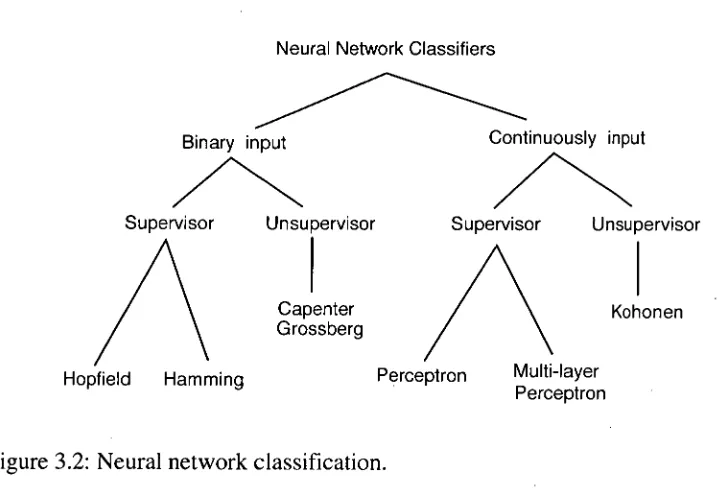
3.2. Neural network classification 26
3.3. Basic neural model 27
3.4. The commonly used nonlinearity activation functions 28
3.5. Feedforward back propagation neural network 29
3.6. Recursive Hopfield neural network 30
3.7. Kohonen neural network 31
3.8. Venn diagrams of crisp (S) and fuzzy (A) sets 37
3.9. Fuzzy set operations 38
3.10. Membership function of a "high" value with linguistic hedges 41
3.11. Basic configuration of a fuzzy system 41
3.12. Shapes of membership functions 42
3.13. A fuzzy loading capability estimator 43
3.14. Linguistic labels and degrees of membership functions 43
of the input variables
3.15. Membership functions of the input variables 44
3.16. Fuzzification process 45
3.17. Representation of FAM rules of the overload-duration estimator 46 3.18. Grades of membership of the crisp inputs 24.5°C and 17.5% 47
3.19. Defuzzification process 49
4.1. Radial basis function neural network 56
4.2. Function link neural network 60
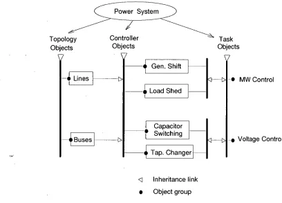
4.3. Object-oriented power system model for preventive control 63
5.4. Life expectancy of insulation as a function of hot-spot temperature 71
A.1. Pictorial diagram of heat quantities 73
B.1. Response of conductor temperature to a short time overload 76
6.1. Variation of the diffuse irradiance as a function of 81
cloud and Albedo parameters
6.2. Hourly global irradiations for different locations (clear-skies) 81
6.3. Hourly solar irradiations for different months 83
(a cloudy-sky condition in Hobart)
6.4. Architecture of the ANN 84
6.5. Comparison of the solar irradiations 85
6.6. Block diagram of the intelligent system 86
6.7. Introduction screen of the IS 90
6.8. Query screen for the "show_conductor" frame 90
6.9. Consultation screen for the conductor data identification 91
6.10. Explanation screen for the wind velocity selection 91
6.11. Consultation screen for the "ask_resistance_ratio" frame 92 6.12. Conclusion screen for the conductor temperature rise study 94
6.13. Conclusion screen for the short-time rating study 94
6.14. Solution search strategy 95
6.15. Temperature - time characteristic for conductor Goat (indoor) 96 6.16. Temperature - time characteristic for conductor 19/0.116" (outydoor) 97 6.17. Temperature - time characteristic for conductor Drake (outdoor) 97
6.18. A 110 kV HEC subsystem 98
6.19. Temperature - time characteristic for the Palmerston-Norwood line 99
6.20. Short time ratings for Palmerston-Norwood line 99
6.21. Conclusion screen of the case studies 100
6.22. Temperature - time characteristics for Palmerston-Norwood line 101 6.23. Short time ratings for Palmerston-Norwood transmission line 102
C.1. Definition of sun's zenith, altitude and azimuth angles 105
C.2. Radiation arriving on the ground 107
C.3. Relationship between the direct normal and the horizontal irradiance 108
C.4. Hourly solar radiation for a clear-sky condition 110
C.5. Hourly solar radiation for cloudy-sky 113
C.6. Solar radiation for different cloudy-skies 114
7.1. Block diagram of the expert system 121
7.2. Solution search strategy of the expert system 130
7.3. One-line diagram of the six-bus power system 131
7.4. Suggested actions to clear the overload on line 2-6 (case 1) 133 7.5. Report on the process of clearing the overload on line 2-6 134 7.6. Suggested actions to clear the overload on line 2-6 (case 2) 135
7.7. One-line diagram of the AEP 57-bus power system 136
7.8. Actions to clear the overloads caused by line 1-16 outage (case 1) 138 7.9. Actions to clear the overloads caused by line 1-16 outage (case 2) 139
8.1. Sensitivity tree for voltage and VAR control 146
8.2. Block diagram of the expert system 147
8.3. Solution search strategy of the expert system 153
8.4. Six-bus power system 154
8.5. Advice on voltage control actions (example 1) 156
8.6. Stability margin of the base case operating condition 159
8.7. The modified IEEE 30-bus power system 160
8.8. Advice on voltage control actions (example 2) 161
8.9. Advice on VAR compensation 162
9.1. Flow chart of voltage and VAR control studies 167
9.2. Pre-contingency power injection conditions at bus i 170
9.3. A model of a complete network with internal sub. and equivalents 172 9.4. The reduced systerrul of the modified IEEE 30-bus system 174
9.5. Advice on voltage control actions 176
9.6. Advice on VAR compensation 177
9.7. One-line diagram of the AEP 57-bus equivalent system 178
9.8. Suggested actions under the outage of line Ll (AEP system) 179
9.9. One-line diagram of the reduced HEC system 181
9.10. One-line diagram of the equivalent network for line Ll outage 182 9.11. Suggested actions under the outage of line Li (HEC system) 183
D.1. Notation for real pOwer at bus i 187
D.2. The procedure of adding (removing) a line using Zbus matrix 189 10.1. Characteristic time periods of system performance after a disturbance 193
10.2. AEP 14-bus power system 196
10.3. Total MVA load vs voltage at bus 5, without VAR support 197
10.4. Total MVA load vs voltage at bus 5, with VAR support 199
10.5. One-line diagram of the reduced HEC system 204
10.6. System performance following a bus fault (without VAR comp.) 205
Tables
3.1. Characteristics of conventional programs and expert systems 20
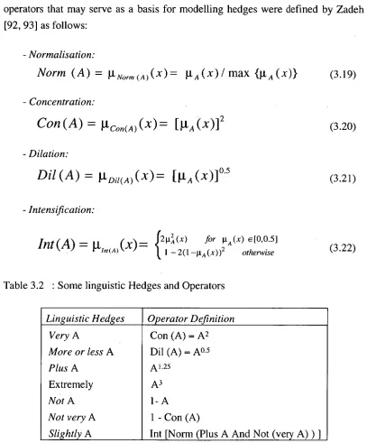
3.2. Some linguistic hedges and operators 40
5.1. Short-term loading capacity for air-cooled transformers 65
6.1. Results of the studies for different cloudy factor 101
6.2. Results of the studies for different operating time 101
C.1. International zone times 106
C.2. Function of sunshine factor 112
C.3. Categories of cloud cover factor 114
7.1. Structure of "linedata" 123
7.2. Structure of "gendata" 123
7.3. Structure of "loaddata" 123
7.4. Bus data of the six-bus system 131
7.5. Clearing the overload on line 2-6 (case 1) 132
7.6. Available actions and sensitivity factors 133
7.7. Clearing the overload on line 2-6 (case 2) 135
7.8. Clearing the overloads on lines 3-4, 12-17, and 13-15 (case 1) 137 7.9. Clearing the overloads on lines 3-4, 12-17, and 13-15 (case 2) 140
8.1. Summary of the voltage control study 155
8.2. Voltage control for the outage of T1 (before VAR compensation) 160
8.3. Controller setting for the outage of transformer Ti 162
8.4. Voltage control for the outage of T1 (after VAR compensation) 163
9.1. Bus voltages for transformer Ti outage 175
9.2. Controller setting for the outage of transformer T1 176
9.3. Suggested locations and sizes of capacitor banks 177
9.4. System voltages before and after voltage correction 180
9.5. System voltages in South Hobart area 184
10.1. Stability margin for the contingency cases (without VAR support) 197
10.2. Summary of the VAR support study 198
10.3. Stability margin for the contingency cases (with VAR support) 199
10.4. Sensitivity factors and stability performance index 206
Chapter 1
Introduction
Steady state security control is an important aspect in power system operation. It deals with operating conditions of a power system as well as with disturbances that could lead to equipment overloads, voltage violations, frequency decay, system instability, service interruption, or the ultimate catastrophe of a system collapse.
System operators play a considerable role in undertaking the security control to enhance operating security in the power system. Their tasks include an identification of whether the power system is currently operating in a secure or insecure condition. If the system condition is insecure, then their responsibility is to determine and execute appropriate control actions to make the system secure.
In principle, the steady state security control can be performed by employing conventional optimisation methods, such as optimal load flow analysis or linear programming. However, such methods rely on mathematical models and sophisticated programming techniques. They can only cover the analytical part of analysis, leaving the burdensome task of making numerous judgements to system operators. Moreover, these methods require large computation time. Therefore, they are not suitable for real-time control of large power systems, in particular, under emergency and abnormal operating conditions when a significant human expertise input is required. To overcome the short-comings of the conventional methods, it becomes necessary to develop new methods for real-time security control.
During the last decade the computational approach to artificial intelligence (Al) has undergone a significant evolution. The application of Al to power systems has resulted in an overall improvement of solutions in many applications [1-4]. This thesis addresses some problems and applications of Al in the security control area in power systems. It also discusses methods which can be used to assist system operators in the determination of the permissible time for alleviating of transmission line overloads and bus voltage violations in power systems.
In this introductory chapter, the states of operation in power systems are described. The functions and natural problems of steady state security control are discussed. Finally, the general principles and objective of the candidate's research are outlined.
1.1. States of Operation in Power Systems
The operation of a power system can be classified into five different states based on the satisfactory condition of the system "equality" and "inequality" constraints [5, 6]. The equality constraints are referred to the system load and generation; and the inequality constraints are referred to some system variables, such as currents and voltages. These operating states are described as follows [7, 8]:
• Normal: is the operating condition in which all constraints are satisfied. Under this condition, all the demands are met at the specified frequency and voltages, and all the system equipment is loaded within acceptable limits. Reserve margin for transmission as well as for generation is sufficient to provide an adequate level of security with respect to any disturbance.
• Alert: in this stage, all constraints are still satisfied, but existing reserve margin is insufficient to provide an adequate level of security such that some disturbance could result in a violation of some inequality constraints. In this insecure alert stage, preventive control actions can be taken to bring the system to the normal state.
Chapter 1: Introduction 3
could be initiated in order to bring the system to the normal or, at least, to the alert stage.
• In extremis: when equality and inequality constraints are violated. This may occur when the specified quality of the supply cannot be maintained and major portions of the system load are lost, or cascade tripping of lines is occurred. It is also possible that the system is in the process of deviation in frequency, or losing synchronism. At this stage, the system is no longer intact, and
emergency control actions should be directed toward salvaging as many pieces
of the system as possible from a total collapse.
Normal
1=1
E, l
c
Restorative
Restorative controlE, I
In Extrem is
Emergency controlE, I
1 Alert
Preventive control
•
(
---- E, I
Emergency
Corrective control i
Note:
" E "
equality constraints
" I " inequality constraints
[image:24.557.143.486.291.662.2]" "1 " negation
• Restorative: here, equality constraints are violated. This stage normally occurs after an in-extremis during which the supply to some customers has been curtailed. Restorative control actions should be directed to pick up all loads lost and to reconnect the system. From this stage, the system could transit to either the alert or the normal stage, depending on circumstances.
Fig. 1.1 shows the system operating states, the transitions and the control methods which are available to system operators for security enhancement. In this figure, the black arrows show the transitions due to control action, and the white arrows show the transitions due to system disturbance.
As shown in Fig. 1.1, for each operating state, an appropriate control method must be used to restore the system to the normal state. Four control methods can be classified as follows:
• Preventive control: this method aims to bring the system from an alert stage to a normal stage, or to improve the system economic performance under the normal stage. The control action solution can be achieved by performing an optimal load flow or an optimisation routine.
• Corrective control: the objective of this method is to bring the system to the normal operating state or, at least, to the alert state. Once a system has entered an emergency state, the deliberate control decisions and actions that are appropriate to the normal, and even the alert, state are no longer adequate and more immediate action may be required. In this control method, a set of control actions must be taken in a very short period of time to avoid a partial or even total collapse of the system. Although mathematical optimisation techniques enable the generation of good results, these techniques are too slow in converging to solution and, therefore, they are not suitable for a real-time control under emergency conditions. In most cases, an experienced operator may be the only important tool with his or her capability to perform very difficult tasks in a short period of time.
Chapter 1: Introduction 5
damping generation swings by switching a 'braking resistor" as a load and so on [9]).
• Restorative control: the control objective is to restore all the supply and bring the system to a normal operating state in minimum time. The control method is achieved almost completely by manual actions. Its difficulty depends not only on how much generation and transmission is available, but also on the operability of auxiliary facilities necessary to place equipment back in service. In general, the system must lend itself to sectionalising so that the load that has been lost can be reenergised in blocks small enough to be manageable. Simultaneously, local energy sources at generating stations must provide adequate power auxiliaries required for unit start-up.
It should be noted that the emergency and restorative control methods are mainly applied in the conditions when the system loses its integrity, which rarely occurs. These control methods are mostly executed by manual actions and based on the operator's heuristic problem solving capabilities, for instance, the operator must be thoroughly familiar with restart procedures to reconnect the system [10-13]. At present, there is no method available to provide a general approach for system restoration. Most electric power utilities maintain their restoration procedures based on certain operating philosophies and practices. These control methods do not belong to the steady state security control scheme and, therefore, are beyond of the scope of this research.
1.2. Security Control Functions
In general, security control is needed to provide continuous supply to all customers, and to avoid damage of power system plant. Three main functions of security control carried out in an operation control centre are as follows [141:
addition, other information such as frequency, generator outputs and transformer tap positions can also be telemetered. The telemetered data are checked against the constraints on power flows, reactive power sources, and voltage magnitudes, etc. If any constraint violation occurs, then the system will be considered insecure and the appropriate control actions are acquired to bring the system into a less insecure or normal state. Otherwise, the system is in normal state and the contingency analysis function is invoked to check on its security level.
It should be noted that in the security monitoring process, the dynamic transition of the system from its operating state to its post-outage steady state can be ignored. This has been discussed and generally accepted as an useful assessment of security [15].
Contingency analysis is used to determine the effects of the transmission line and generator outage contingencies on the steady state performance of the system at its current operating condition. This function permits system operators to establish defensive operating states where no single contingency will cause overloads and/or voltage violations. Basically, it determines the possibilities that the system will ride through the disturbance and settle down to a normal state, or it will find itself in an emergency. In the latter case, the system is insecure and the operator must be informed to enable him or her to take adequate actions in order to prevent the anticipated emergency.
Control action analysis the objective of this function is to select a set of preventive or corrective control actions which are needed to bring the system back into a normal operating state when an event of overload or voltage violation occurs. The control actions may be executed manually or automatically, and immediately or gradually, depending upon the severity of the insecure operating condition. For instance, if the insecure condition is in the alert operating state which is not very critical, then control action may be achieved by shifting generation from units in trouble to other available units. Otherwise, a severe steady state emergency may require immediate load shedding, which can be done manually by supervisory control or automatically by the computer.
The instigated control action could be [16]:
Chapter 1: Introduction 7
- modification of scheduled exchange tie line powers,
- changes in the network configuration,
- prearranged curtailment of some interruptible loads if there are no logical or economic alternatives to a vulnerable situation.
1.3. Natural Problems of Security Control
Power system equipment, such as a transmission line, transformer or generator, is designed to be operated within certain limits. Automatic devices, such as circuit breakers and switches, are utilised in the protection scheme to switch the equipment out of service if these limits are violated. However, as a result of any failures, which may occur due to lightning strikes, system faults, or human errors in relay setting, the equipment may still be left in operation with limits violated. Such conditions may lead in turn to switching of other equipment out of service. If this process continues, the entire system or large parts of it may completely collapse. One of the options to avoid the collapse is to increase the system reliability. This can be done by operating all system plants within their design capability, and reinforcing the network topology of the system in a way to avoid any overload and voltage violation problem occuring under single and certain double-contingency outages [17]. However, it is highly uneconomical to build such a system with so much redundancy (ie. extra transmission lines, reserve generation, etc.) to guarantee 100% reliability, and it is noted that to build the
100% reliable system an unlimited budget should be available. Most power systems are designed to have sufficient redundancy to withstand all major failures only. In common practice, the system should be operated such that any single initial failure will not leave other components overloaded in order to avoid voltage violation problems and cascading failures [14].
increasing both in size and complexity. This poses computational difficulties and is time consuming when security analysis is conducted on the whole system using conventional methods to evaluate system quantity and reliability. Also, due to an uncertainty in the power demand forecast and economic reasons, the power systems may be operated under highly stressed conditions, ie. the systems are being operated very close to their security limits. The higher level of stress causes system reliability to decrease. This makes the task of security control difficult for the system operators. Furthermore, the conventional methods are implemented with no direct provision for exploiting the operator's knowledge and they cannot provide an interactive mode interface to users. Therefore, they are not suitable for real-time control, in particular, under emergency and abnormal operating conditions.
For these reasons, power utilities are now requiring new tools to formalise the operator's knowledge and run in the real-time mode in order to perform the functions of operator aid in emergency operating conditions. In addition, such tools should include the facilities to assist system operators in the identification of the system operating stressed conditions, in other words to determine the distance to a voltage collapse or the limiting time for overloading a transmission line.
1.4. General Principles and Research Objective
Power system steady state conditions can be described by the power flow equations [23]:
IV
Pk = PkSP — AP k = Vk
E vn
(au,cosokn
+ Bktt sin ob2)n=1
N
Qk
=
QkSP-
AQk=
VkE
Vn (Gkn sin 6kn—
Bkn COSSicn)n=1
(1.1a)
(1.1b)
Chapter 1: Introduction 9
[A Q
A P H A 8
1 [ J I_ [A V (1.2)
The power flow equations are non-linear and therefore, it is possible to find multiple solutions or in some cases no solution at all [25, 26]. Moreover, the solutions of the non-linear power flow equations based on the full AC load flow model are iterative in nature and thus extremely time consuming. However, computation time can be improved by using an approximated model of the power system, such as the decoupled load flow model [27, 28]:
[AP] = [H] [M] (1.3a)
[AQ] = [L] [AV] (1.3b)
This model exploits an important characteristic of any practical electric power transmission system operating in steady state, that is the strong relationship between real powers and bus voltage angles and between reactive powers and voltage magnitudes. Based on this, the following principles can be applied to alleviate overload and voltage violation problems in order to bring the system into a normal operating state:
• overloads on transmission lines can be relieved by appropriate change in the voltage angles. This is done by shifting active power flow in the system.
• system voltages can be maintained within certain limits by suitable allocation of reactive power injection in the system.
Steady State Security Control
Analysis Via Conventional Methods
This chapter presents a discussion on the conventional methods employed in the steady state security control analysis. The chapter is divided into three sections. The first section describes the basic software tools and their functions in the security control analysis. The second section provides an overview of the conventional methods and their disadvantages, and the last section gives reasons for the need of artificial intelligence application in the security control area.
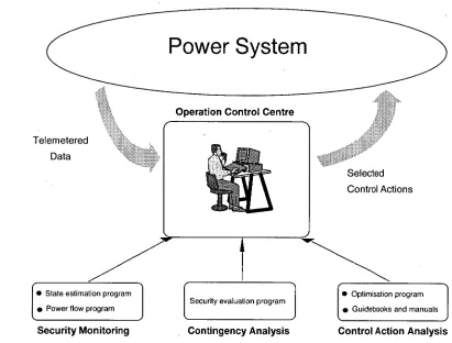
2.1. Tools for Steady State Security Control Analysis
Basically, the following tools are required in an operation control centre for the steady state security control analysis:
• A state estimation program which uses the redundancy of the on-line measurements gathered from a telemetry system to determine the most likely values of bus voltages and line power flows.
• A power flow program, such as AC load flow, to allow the operator to study the effects of changes in the operating conditions on the state of the network.
• A security evaluation program which determines whether or not the failure of any power system equipment would cause a violation of the system security constraints and provides warning messages.
Operation Control Centre
Telemetered Data
Selected Control Actions
Security Monitoring Contingency Analysis Control Action Analysis • State estimation program
• Power flow program Security evaluation program
• Optimisation program • Guidebooks and manuals Chapter 2: Steady State Security Control Analysis
via Conventional Methods 11
• Optimisation programs, such as optimal load flow, to calculate optimal settings for the control variables to minimise the operation cost and system losses while satisfying the security constraints.
[image:32.557.78.489.250.562.2]• Guidebooks and manuals with heuristic rules, guidelines and remedial actions to deal with some typical system failures.
Fig. 2.1 shows the utilisation of these tools for security control analysis.
Figure 2.1: Tools for security control analysis.
2.2. Conventional Methods with Disadvantages
In general, as shown in Fig. 2.1, security control analysis includes three major steps and is carried out in the following order:
[29-31], then a load flow method is utilised to check whether or not the limits are violated.
(ii) next, the determination contingencies leading to violations of the power system equipment limits and ranking of these contingencies in an order of violation severity must be performed.
(iii) lastly, a set of control actions is recommended for each case to bring the system into a normal operating condition.
An overview of the conventional methods involved in these steps of security control analysis, and discussion on short-comings of the application of these methods is given below:
i) In the process of security monitoring, a direct approach would involve performing a full AC load flow for each contingency, followed by a check for limit violations [32, 33]. In current practice, the analysis would be limited to contingencies of a single component. However, a pre-specified set of multiple component outages might also be included. For large power systems, even if only single contingencies were considered, such an approach would be difficult to implement since the Newton-Raphson AC load flow model requires an excessive memory storage and prohibitive computing time. It should be noted that this method is regarded as slow but can provide accurate voltage solutions.
In order to improve the computation speed and reduce the memory storage problems several other methods have been introduced. They include the matrix treatment with sparsity and refactorisation techniques [34, 35], the DC and AC linear load flow [36, 37], the decoupled and fast decoupled load flow [27, 28, 38, 39], etc. These methods have been successfully implemented in the security control analysis [40-44]. However in a comparison with the full AC load flow method, each of them have some disadvantages. For instance, the DC load flow methods are fast, but provide no voltage information [45]. The fast decoupled load flow methods provide voltage information with less computation, but they do have convergence difficulties in solving the load flow problem of some networks having relatively high R/X ratio branches [46].
Chapter 2: Steady State Security Control Analysis
via Conventional Methods 13
sequentially to evaluate the effects of line and generator outages on the system performance and reliability. Such an approach can be extremely time consuming for large power systems. In order to cope with the computational burden, a number of methods have been developed. Basically these methods can be divided into two classes, the ranking and screening methods:"
• The ranking methods [47-52] are based on the idea that the majority of contingencies do not cause major shift violations, and quantify each contingency in a list, called the contingency list, by a scalar performance index which measures the system stress without actually calculating the post-contingency line flows or voltages. The contingencies are ranked in an approximate order according to their performance index values, and tested by a full AC load flow starting with the most severe case and proceeding down to the cases where no violations exist. At this stage, there is no need to proceed with further testing, since all remaining contingencies are less severe. Such methods are fast, but not completely reliable and do not detect all insecure cases because of approximations and inaccuracies in the ranking process, which may be due to the following considerations: (a) magnitude of violation, (b) number of violations occurring, (c) relative importance of each violation, and (d) nearness to security limits.
considerably fast, but critical points of these techniques, the solution speed and accuracy, would depend on the selection of buses in which calculations have to be done.
iii) As already discussed in Section 1.3, in the process of control action analysis, the traditional approach of making decisions on control actions to be applied is based on the solution of the conventional optimisation methods, and the experienced operator judgement stored in the guidebooks. The conventional methods include the implementation of the optimal load flow [60-63], the non-linear [64, 65] and non-linear programming techniques [66-71]. However, these methods have been proposed for the real-time application under normal operating conditions [69, 70] and even in emergency conditions [71]. But in fact, none of them would be applicable for real-time applications because of their complexity and incapability to provide direct advice to the system operators in the form of non-analytical solutions and large time demand. Moreover, these methods do not take into account the human experience, which is essential to provide judgements for solving abnormal problems when no practical solutions can be obtained from conventional mathematical model.
In the next section, a summary of short-comings of the conventional methods and an outline of needs for application of Al in the security control analysis are given.
2.3. Recognised Needs for Artificial Intelligence Application
It is reasonable to summarise now the short-comings of the conventional methods described above.
Chapter 2: Steady State Security Control Analysis
via Conventional Methods 15
probably not being adequately trained to faced the difficult task of operating a power system in the event of a major fault. As a result, there could be a lack of expertise required even to formulate problems in the operation of power systems.
• Modern operation control centres are equipped with supervisory control and data acquisition (SCADA) systems that allow system operators to monitor the generation and high voltage transmission systems and to take actions to correct problems remotely. The SCADA systems also provide data on-line which is suitable for real-time security analysis. But the conventional methods employed for power system security analysis are extremely time consuming for large power systems and cannot be used in the real-time security control. In emergency and abnormal operating conditions, operators are often fully occupied. They have to deal with a large amount of data and select the most appropriate remedial actions. Besides, due to emotional and psychological stress, the operators may not be able to adequately respond to critical conditions by looking into long columns of results and using their experience in order to find a right decision. Specifically, under these circumstances, there is no time for them to examine advantages and disadvantages of different approaches to the correction or restoration process when decision on control action making must often be taken in a matter of minutes, sometimes even seconds. Mistakes can damage very expensive power system equipment or worse lead to major emergencies and catastrophic situations.
• The conventional methods rely on mathematical models and sophisticated programming techniques. They can only cover the analytical part of analysis, leaving the burdensome task of making numerous judgements to the operators. Moreover, these methods cannot provide an interactive mode interface to users. In other words, they cannot provide direct advice to system operators on the appropriate actions required to overcome the problems.
developed to analyse and optimise power systems operating in a normal, quasi-steady state. But, no practical method has been developed so far to deal with the system during emergency conditions.
In order to cope with the difficulties of the conventional methods, there is a need to develop new methods which allow facilities to formulate the operator knowledge and provide a man-machine interface, so that computational speed would be improved and hence suitable for real-time security control. For that reason, to achieve the purpose of real-time steady state security control analysis, a powerful tool is required with the following provision goals:
• identification of alert and emergency operating conditions; • indication of operating security stress condition;
• improvement of computer processing capability;
• implementation of the operator's heuristic problem solving capabilities;
• provision of man-machine interface;
• provision of non-analytical solution on remedial actions.
Chapter 3
Background of Artificial Intellience Techniques
Although artificial intelligence is not a new topic and the concept of artificial intelligence was introduced in the 1950s [72, 73], the problem-solving potential of artificial intelligence has been exploited only recently. During the last decade artificial intelligence techniques have captured interest in many fields of engineering, particularly in electric power engineering, and this trend is likely to be continued. According to reference [74], current directions of artificial intelligence research can be broken into three approaches:
• psychological - to discover how humans think so that this can be simulated by computers using heuristic rule approach;
• connectionism - the structure of the interconnected neurons in the human brain is emulated by artificial neural networks for computers. This relies on parallel distributed processing;
• mathematical - using formal logic where the principles of reasoning are clearly combined.
In basic artificial intelligence fields, the promising concept for building decision-support systems, to include the knowledge of human experts and natural phenomena using the methods of knowledge acquisition and knowledge transformation, is the combination of rule-base method, neural network computing, and fuzzy set theory. The "IF - THEN" rule-based method usually deals with both quantitative and qualitative heuristic knowledge. Neural computing is based on the teaching samples set that is suitable for transformation
of the completely black-box type of knowledge. Fuzzy set theory basically deals with uncertainties so that it can be used as a mechanism to incorporate engineering judgement in the decision making process.
This chapter is divided into four sections. The first three sections provide a very basic overview of artificial intelligence techniques. These techniques include expert system, neural networks and fuzzy logic and are separately presented in each section. Within each section, a definition of the AI technique is given first, then followed by a description of the components and concepts utilised in the technique, and a general discussion on the advantages and limitations of the technique is provided at the end of the section. The last section discusses future evolution of artificial intelligence.
Nomenclature
x1 . Input signal of neuron i;
Yi Output signal of neuron i;
wi = [w1, w2, wni Weighting factors;
Weighted connections between input neuron i and each output neuron j;
Output threshold value;
d. Distances between input and each output neuron j;
{X, Set of elements x;
belongs to;
V for all;
if and only if; Union of fuzzy sets; Intersection of fuzzy sets;
gs(x) Characteristic function of crisp set s;
11A(x) Characteristic function of fuzzy set A;
iiNorm (A)(X) Normalisation of fuzzy set A;
Chapter 3: Background of Artificial Intelligence Techniques 19
3.1. Expert Systems
Expert systems can be defined as computer programs which incorporate judgement, experience, heuristics, intuition, and other expertise to provide knowledgeable advice like human experts in some domain. They are particularly useful for making expert advice readily accessible, so that non-experts can use them to solve problems in a comparable way to domain experts.
The technology represented by current expert systems is an outgrowth of artificial intelligence techniques that have been the subject of intensive research since the late 1960s [75]. Expert systems derive their capacity of solving problems from the domain knowledge they possess. Therefore, each expert system has knowledge in a particular domain and is only capable of solving problems which require that knowledge.
Expert systems differ from conventional computer programs in several ways. Perhaps the most basic differences are as follows:
• expert systems manipulate knowledge while conventional computer programs manipulate only data.
• expert systems are characterised by the use of heuristics (rules of thumb) in their problem solving activities, while conventional computer programs are algorithmic in nature and are characterised by the use of repetitive processes.
• expert systems solve problems by manipulating symbols and not just by performing mathematical calculations or solving equations as conventional computer programs do so.
A symbol can be thought of as a string of characters that represents some real- world concept, such as bus voltage _ or 0.9. These symbols may be used in a symbolic structure to represent some real-world relationship. An example of such a structure might be as,
IF bus _voltage < 0.9
Some of the distinguishing characteristics of conventional computer programs and expert systems are listed in Table 3.1 [76].
Table 3.1: Characteristics of Conventional Programs and Expert Systems
Conventional programs Expert systems
- Representation and use of data, - Representation and use of knowledge, - Knowledge and control integrated, - Knowledge and control separated, - Algorithmic (repetitive) process, - Heuristic (inferential) process,
- Effective manipulation of large data bases, - Effective manipulation of large knowledge bases, - Programmer must ensure uniqueness and - Knowledge engineer inevitably relaxes uniqueness
completeness, and completeness restraint,
- Midrun explanation impossible, - Midrun explanation desirable and achievable, - Oriented toward numerical processing. - Oriented toward symbolic processing.
Today, expert system builders can develop their expert systems based on the use of one of the two available methods. These methods include high-level programming languages and expert system shells (also known as knowledge engineering languages).
The high-level programming languages that are used for expert system applications include procedure-oriented languages such as Pascal and C, and symbolic-manipulation languages such as Lisp and Prolog. There are some advantages and disadvantages with the use of these high-level programming languages. The main advantage is the flexibility that allows expert system builders to design their system for solving a wider variety of problems within the same domain. The disadvantage is that these languages are difficult to apply because they give no guidance and mechanism of how knowledge should be represented.
Chapter 3: Background of Artificial Intelligence Techniques 21
reduce the amount of resources required for the development of expert systems. The disadvantage is that the range of problems which can be solved in a given domain is limited to the constraints enforced by the shell.
There are a number of expert system shells available today. Each of them has different benefits and limitations. The benefits may include the capability of providing access to external programs, databases, graphical editors, etc. The limitations may include the limits on run-time storage memory and the number of rules represented in the knowledge base of the application to be developed. Because, in general, different shells are applicable to different types of applications, a mismatch may reduce the chance of successfully implementing a system. Therefore, the selection of a suitable shell which matches the application to be built plays a very important role in the development of expert systems using knowledge engineering languages. An outline of benefits and limitations of several available expert system shells can be found in [77].
3.1.1. Architecture of an expert system
The architecture of an expert system is difficult to define because of the variation in the tools and languages in which the expert systems are developed. Development of an expert system can be conveniently based on three main components: the knowledge base, the inference engine and the user interface. Additional components, such as the context and explanation facility, can be included to make the expert system more user-friendly. The relationship between these components is illustrated in Fig. 3.1.
a) Knowledge base is the component of the expert system that comprises specific knowledge in the domain of application, including simple facts about the domain, rules that describe relations or phenomena in the domain, and possibly methods, heuristics and ideas for solving problems in the domain. Knowledge can be structured into production rules, each of which represents a single piece of knowledge and takes the form:
IF (antecedent) THEN (consequent)
Knowledge Base
If - Then rules Inference Engine
Explanation
Facility Context
User Interface
Figure 3.1: Architecture of an expert system.
b) Inference engine is the part of the expert system that contains the control information. The inference engine applies the knowledge base to solve a problem. It directs or controls the operation of the expert system, deciding which rules to• apply, how they will be applied, when the process is completed, when a possible solution can be suggested, and modify and expand the context. Many strategies for solving problems have been proposed because as more expert system applications are being developed, the understanding of problem solving strategies improves. Four of the most common strategies, known as forward chaining, backward chaining, mixed chaining, and agenda control are discussed below:
Forward chaining: a system uses forward chaining strategy if it works from an
initial state of known facts to a goal state. The forward chaining system attempts to watch known facts with antecedents of production rules, and fires the rules accordingly. Executing the consequents of these rules adds new facts to the knowledge base. This continues until either a goal consequent is performed, or the available facts cannot be used to infer any other new fact, and the result is unknown.
Backward chaining: a system uses backward chaining strategy if it assumes a goal
Chapter 3: Background of Artificial Intelligence Techniques 23
causes consideration of further rules which would confirm the required antecedents.
Mixed chaining: this strategy is a combination of the forward and backward chaining strategies. Initially, the system starts with the known facts to assign a probability to each of the potential goal states. Then the system supports the goal state with the highest probability by setting up subgoals and requesting additional information from the user if necessary. The system uses the information supplied by the user to identify the solution, and the order in which the hypotheses are checked depends on the problem under consideration. In this strategy, it is considered that if an initial hypothesis is disproved, the next assumption is made according to current information.
Agenda control: this control strategy can be used for complex tasks that require' focusing attention on certain parts of the problem, and it can also be used in systems that require several independent sources of expertise to communicate with one another. In this control strategy, each task in an agenda is assigned by a priority rating, and the task with highest priority is performed first. A list of justifications and a method of determining the priority rating is associated with each task.
c) User interface of the expert systems extends the traditional capabilities of conventional user interface, and provides a smooth communication between the user and the system. It is vital that this communication be as meaningful and friendly as possible, perhaps with 'HELP' facilities. The user interface may be command driven, menu-driven, or icon oriented (graphical objects). It may also provide the user with an insight into the problem-solving process executed by inference engine.
e) Explanation facility varies from a trace of execution to the ability to respond to the questions about the reasoning process which is used to develop a solution. The facility allows the system to explain to a user how a solution was determined, and/or what decisions were made to reach a conclusion.
3.1.2. Advantages and limitations
The following advantages may be noted for expert systems:
• expert systems can be developed to solve some problems currently solved by human experts. This can reduce tedious and redundant manual tasks, leading to efficient operation.
• the knowledge base can be gradually and incrementally developed over an extended period of time. Each production rule of the knowledge base represents a piece of knowledge relevant to the task which can be added, removed and modified as experience is gained.
• an expert system has the ability to solve problems involving heuristic and symbolic computation.
• an expert system can explain its behaviour through an explanation facility.
• production rules are close to natural language, and easy to understand.
• the knowledge base is problem domain dependent, but the inference engine is domain independent. Therefore, a general system with one inference engine can be developed for different types of applications simply by changing the knowledge base.
• expert systems can provide the right expertise whenever needed. In particular, expert systems can provide more rapid solutions to emergency events than human operators.
Chapter 3: Background of Artificial Intelligence Techniques 25
• expert systems are best applied to problems that have limited and defined domains; but for the problems which are complex and not so well-defined, expert systems may fail to provide precised solutions.
• the knowledge base of expert systems may contain uncertainties and inaccuracies. They are either associated with the inference rules given by the experts, or deduced from the observation of facts which do not fit exactly the conditions expressed in the premises of the rules.
• expert systems do not have the capacity to generalise. In other words, they do not learn and fail in the presence of insufficient information.
• They are suitable for problems involving deduction and not so much for problems involving induction or analogy.
• They lack the speed to perform symbolic computations.
3.2. Neural Networks
A neural network is an artificial (man-made) system motivated by the neural structure observed in real biological organisms of the human brain. A neural network consists of a large number of simple processing elements, called neurons
or units, operating in parallel and connected to each other by a system of axons
and dendrites or connections, along which relatively simple signals are passed.
This network is capable of learning and storing some associations. According to Aleksander and Morton' s definition [78]:
"A neural network is a massively parallel distributed processor that has a
natural propensity for storing experiential knowledge and making it
available for use. It resembles the brain in two respects:
1. Knowledge is acquired by the network through a learning process.
2. Interneuron connection strengths known as synaptic weights are used