This is a repository copy of Simple, Direct Routes to Polymer Brush Traps and Nanostructures for Studies of Diffusional Transport in Supported Lipid Bilayers. White Rose Research Online URL for this paper:
http://eprints.whiterose.ac.uk/117155/ Version: Accepted Version
Article:
Johnson, A., Bao, P., Hurley, C.R. et al. (4 more authors) (2017) Simple, Direct Routes to Polymer Brush Traps and Nanostructures for Studies of Diffusional Transport in Supported Lipid Bilayers. Langmuir, 33 (15). pp. 3672-3679. ISSN 0743-7463
https://doi.org/10.1021/acs.langmuir.7b00497
[email protected] https://eprints.whiterose.ac.uk/
Reuse
Unless indicated otherwise, fulltext items are protected by copyright with all rights reserved. The copyright exception in section 29 of the Copyright, Designs and Patents Act 1988 allows the making of a single copy solely for the purpose of non-commercial research or private study within the limits of fair dealing. The publisher or other rights-holder may allow further reproduction and re-use of this version - refer to the White Rose Research Online record for this item. Where records identify the publisher as the copyright holder, users can verify any specific terms of use on the publisher’s website.
Takedown
If you consider content in White Rose Research Online to be in breach of UK law, please notify us by
Simple, direct routes to polymer brush traps and
nanostructures for studies of diffusional transport in
supported lipid bilayers
Alexander Johnson,1,2 Peng Bao,3 Claire R. Hurley,1† Michaël Cartron,4 Stephen D. Evans,3 C.
Neil Hunter4 and Graham J. Leggett1,2*
1
Department of Chemistry, University of Sheffield, Brook Hill, Sheffield S3 7HF, UK; 2Krebs
Institute, University of Sheffield, UK; 3Molecular and Nanoscale Physics Group, School of
Physics and Astronomy, University of Leeds, Leeds LS2 9JT, UK; 4Department of Molecular
Biology and Biotechnology, University of Sheffield, Western Bank, Sheffield S10 2TN, UK
ABSTRACT
Patterned poly(oligo ethylene glycol) methyl ether methacrylate (POEGMEMA) brush structures
may be formed by using a combination of atom-transfer radical polymerization (ATRP) and UV
photopatterning. UV photolysis is used to selectively dechlorinate films of
4-(chloromethyl)phenyltrichlorosilane (CMPTS) adsorbed on silica surfaces, by exposure either
through a mask or using a two-beam interferometer. Exposure through a mask yields patterns of
carboxylic acid terminated adsorbates. POEGMEMA may be grown from intact Cl initiators that
patterning of proteins, vesicles and, following vesicle rupture, supported lipid bilayers (SLBs).
Bilayers adsorbed on the carboxylic acid terminated surfaces formed by C-Cl bond photolysis in
CMPTS exhibit high mobility. SLBs do not form on POEGMEMA. Using traps consisting of
carboxylic acid functionalized regions enclosed by POEGMEMA structures, electrophoresis may
be observed in lipid bilayers containing a small amount of a fluorescent dye. Segregation of dye
at one end of the traps was measured by fluorescence microscopy. The increase in the
fluorescence intensity was found to be proportional to the trap length, while the time taken to
reach the maximum value was inversely proportional to the trap length, indicating uniform, rapid
diffusion in all of the traps. Nanostructured materials were formed using interferometric
lithography. Channels were defined by exposure of CMPTS films to maxima in the
interferogram, and POEGMEMA walls were formed by ATRP. As for the micrometer-scale
patterns, bilayers did not form on the POEGMEMA structures, and high lipid mobilities were
measured in the polymer-free regions of the channels.
INTRODUCTION
Lipid membranes play a central role in biology: they form the cellular membrane, separating
the interior of the cell from its external environment, and they provide the means by which the
interior of the cell is compartmentalized into discrete organelles.1 Understanding how biological
systems use compartmentalization is a fundamental scientific challenge, and one that is also
intricately connected with attempts to build biologically-inspired nanosystems.2-3 However,
native lipid membranes are difficult to study in situ. Supported lipid bilayers (SLBs) provide a
convenient model for biological lipid membranes, facilitating direct interrogation by a plethora
of techniques, including spectroscopic methods,4 quartz crystal microbalance measurements,5
adsorption, fusion and rupture of vesicles from an aqueous solution onto a clean oxide
substrate.6-7 Although the precise mechanism for this process is not fully understood, it is thought
that electrostatic interactions between the lipids and substrate play an important role.8 Clean
silica substrates,9 or other inorganic surfaces such as mica, have been widely used; vesicles
rupture readily on these surfaces to form continuous and highly mobile SLBs. There has also
been much interest in forming SLBs on other surfaces, including polymers.10-12
The dynamical behavior of lipids and membrane components is important in controlling many
biological processes.13 For example, bacterial photosynthesis is driven by a variety of membrane
transport processes, including intra-membrane transfer of charge, via diffusion of quinols, and
transmembrane proton transport through the activity of cytochromebc1 and ATPsynthase.14-15 In
eukaryotes, Groves and co-workers have demonstrated the importance of intra-membrane
transport in the immune system. Using “mazes” (collections of staggered lines) formed from
100-200 nm wide, 5.5 nm high chrome structures at 1.5 – 2 m spacings, they were able to
investigate the role of spatial organization in T-cell receptor signalling.16 It was found that the
recognition of a peptide antigen by T cells involves coordinated movement of T cell receptors
(TCRs) along with other co-stimulatory and signaling molecules, leading to the formation of
immunological synapses, in which cluster size directly influences protein spatial positioning.17
However, in a review of bilayer patterning techniques, DeMond and Groves noted a wide range
of significant experimental challenges. In particular, there are few reliable methods for control of
bilayer organization,18 and substantial problems associated with the incorporation of
transmembrane proteins into supported lipid bilayers.
There has been interest in the formation of patterned SLBs for use in studies of electrophoresis.
moved. This was first demonstrated by Sackman et al, who used electrophoresis to determine the
mobility and diffusion coefficients of lipids in an SLB.19 Yoshina-Ishii and Boxer continued this
work by showing that it was possible to manipulate lipids within membrane arrays.20 More
recently, Cheetham and Roth and coworkers published a series of papers in which ratchet
structures were fabricated by photolithography and micro-contact printing for the movement and
[image:5.612.82.536.239.413.2]concentration of both lipids and membrane proteins within SLBs.21-24
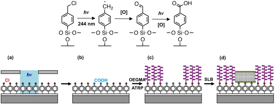
Figure 1. Top: reaction scheme for the photochemical oxidation of CMPTS. Bottom: schematic
diagram showing the fabrication of SLBs confined by poly(oligoethylene glycol)methacrylate
brushes.
The present work reports a new approach to the fabrication of structures for the investigation
of dynamic phenomena in SLBs (Figure 1). The method is effective across a wide range of
length scales, from hundreds of m to tens of nm, and relies upon simple chemistry. When
4-(chloromethyl)phenyltrichlorosilane (CMPTS) is exposed to UV light, photolysis of the C-Cl
bond occurs to create first an aldehyde and then a carboxylic acid (Fig. 1b).25 This rapid process
enables the definition of hydrophilic, anionic regions in which SLBs may be formed. Lipid
“walls” are grown from unmodified regions of the sample by atom-transfer radical
polymerization (ATRP)26-27 of oligo(ethylene glycol) methyl ether methacrylate (OEGMEMA),
using intact Cl as the initiator (Fig 1c); SLBs are then deposited by standard methods into the
carboxylate regions (Fig 1d). Trap structures were formed and used in studies of electrophoresis.
ATRP of OEGMEMA28-31 and of zwitterionic monomers such as 2-methacryloloxyethyl
phosphorylcholine,32-33 sulfobetaine methacrylates34 and amino acid methacrylates35 has been
shown to be a very effective means of passivating surfaces against adsorption of biological
molecules.36-37 By carrying out exposure using a two-beam interferometer, nanostructured
polymers were also formed that enclosed nanostructured lipid channels, and used to study
diffusional transport in confined environments.
EXPERIMENTAL SECTION
Silicon wafers (test grade, B-doped, <100>, 380 m thick) were supplied by Pi-KEM
(Peterbrough, UK). Copper electron microscope grids (1000-2000 mesh) were obtained from
Agar Scientific (Stanstead, UK). 4-(Chloromethyl)phenyltrichlorosilane was obtained from Alfa
Aesar (Heysham, UK). oligo(ethylene glycol) methyl ether methacrylate (Mn 475), 2,2’
-bipyridyl (Bipy, >99%), copper (I) bromide (99%) and copper (II) bromide (99.5%) were
obtained from Sigma-Aldrich (Poole, UK). 1-palmitoyl-2-oleoyl-sn-glycero-3-phosphocholine
(POPC) and 1,2-dioleoyl-3-trimethylammonium-propane (DOTAP) were purchased from Avanti
Polar Lipids (Alabaster, AL). Atto 590 labeled 1, 2-dioleoyl-sn-glycero-3-phosphoehanomamine
(Atto590-DOPE) and Atto 488 labeled 1, 2-dioleoyl-sn-glycero-3-phosphoehanomamine
(Atto488-DOPE) were purchased from Atto-TEC (Siegen, Germany).
To prepare polymer brushes by ATRP, samples were placed in carousel tubes, sealed, degassed
added to monomer and the solution degassed for 30 min. To the monomer solution, 0.37g of
copper (I) bromide and 0.81 g of 2,2’-bipyridyl were added and the solution was degassed for a
further 5 min and sonicated. 1-2 mL of the monomer-catalyst solution was added to the carousel
tubes and the samples were left to polymerize for various times (to control the brush thickness).
Once the polymerization was complete the samples were sonicated in water, rinsed with ethanol
and blown dry with nitrogen.
Dried lipids (DOTAP:POPC:Atto590-DOPE = 24.9:74.6:0.5) were dissolved in a 50:50
mixture of HPLC-grade chloroform and methanol and transferred to glass vials. The lipids were
dried under a flow if nitrogen for 1 h and re-hydrated using phosphate buffer (a 10 mM mixture
of sodium dihydrogen phosphate and disodium hydrogen phosphate in deionized water, adjusted
to pH 7.1 with NaOH or HCl. Vesicle solutions (1.0 mg mL–1) were prepared by vortex mixing
for 1 min (Vortex Genie2, Jencons Ltd, Leighton Buzzard, UK) to create multilamellar vesicles
as a cloudy suspension. Small unilamellar vesicles were prepared by tip sonication of the
aforementioned solution (Branson Sonifer 750, Branson Ultrasonics Corp, Danbury, CT) at 4 °C
for 30 min, during which time the suspension became clear. The suspension was centrifuged
(Heraeius Fresco 17, Thermo Fisher Scientific, Loughborough, UK) for 1 min at 14 500 g, after
which the Ti precipitate (formed at the surface of the tip of the sonicator during the tip-sonication
process) was removed and the supernatant was retained. The suspension was diluted with
phosphate buffer to 0.5 mg mL–1 prior to use and stored at 4 °C in the dark for no longer than 5
days.
Bilayer formation was carried out in a custom-built flow cell. For bare glass substrates, the
vesicles were injected and incubated for 1 h at 22 °C. The samples were rinsed subsequently for
patterns, the samples were first soaked in buffer solution for 10 min, followed by injection of
vesicles, incubation and rinsing.
Photopatterning was carried out using a Coherent Innova 300C frequency-doubled argon ion
laser (Coherent UK, Cambridge, UK) emitting at 244 nm. Micropatterns were formed by
carrying out the exposure through a mask. Interferometric lithography was carried out as
described previously using a Lloyd’s mirror interferometer in combination with the same laser.
The laser beam was directed at a sample stage and mirror held at an angle 2 relative to each
other, such that half the beam struck the sample and the other half struck the mirror from where
it was reflected onto the sample to interfere with the first half of the beam. The resulting
interferogram had a sinusoidal cross-section with a period /2sin.
X-ray photoelectron spectroscopy (XPS) was carried out using a Kratos Axis Ultra X-ray
photoelectron spectrometer equipped with a monochromatized X-ray source operating at a power
of 150 W and emission current of 8 mA. Samples were mounted using double-sided adhesive
tape, and an electron flood was used to compensate for sample charging. Electron energy
analyzer pass energies of 160 eV and 20 eV were used to acquire wide (survey) spectra and high
resolution spectra, respectively. Data were analyzed using CasaXPS software (Casa,
http://www.casaxps.com, UK).
Secondary ion mass spectrometry (SIMS) was carried out using an IonToF SIMS V imaging
secondary ion mass spectrometer (IonToF, Münster, Germany), equipped with a bismuth cluster
source and a single-stage reflectron time-of-flight mass analyzer. A minimum of 2 spectra per
sample and multiple samples were analyzed. High mass-resolution images were obtained by
using high-current bunched mode, with Bi2+ as the primary projectile and a target current of 0.1
Fluorescence microscopy was carried out using an epifluorescence microscope (Nikon
Instruments Europe, B.V., Kingston, UK). Fluorescence images were captured using a 12-bit
greyscale digital camera, Orca-ER (Hammamatsu Photonics UK Ltd, Welwyn Garden City,
UK).
Atomic force microscopy was carried out using a Digital Instruments Nanoscope IV
Multimode instrument (Veeco, Santa Barbara, USA) equipped with a ‘J’ scanner (0 – 125 m).
In contact mode, silicon nitride nanoprobes with nominal force constants of 0.06 or 0.12 N m–1
and tip radii in the range 20 – 60 nm were used (Bruker, Coventry, UK). In tapping mode silicon
probes with spring constants between 20 and 80 Nm–1 were used (Bruker). Prior to analysis
samples were washed with ethanol and dried under a stream of nitrogen. Samples were then
secured to a metal disc using double-sided adhesive tape.
Fluorescence recovery after photobleaching (FRAP) was carried out using an epifluoroescence
microscope (E600 Nikon, USA). A small amount of Atto590-DOPE was introduced to the lipid
mixture, and the sample was illuminated and bleached by a high pressure mercury arc lamp. The
bleached spot radius was 14 m when using a 40 objective lens. Fluorescence images were
collected using a Zyla sCMOS CCD (Andor Technology Ltd, Belfast, UK) with 2 2 binning,
and recorded on NIS elements software. Images were collected until complete fluorescence
recovery was observed. The Axelrod method of analysis38 was employed, which provides both
the diffusion coefficient and the mobile fraction.
Electrophoresis was carried out in a home-built flow cell, which served to maintain the
membrane in an aqueous environment and facilitate the connection of external electrodes to the
on-substrate interdigitated electrodes. An arbitrary waveform generator (Thurlby Thandar
electrical signal for the experiments. Currents of 10 – 100 A between the electrodes were
monitored using a Keithley picoammeter (Keithley Instruments Ltd, Theale, UK). A constant
flow of degassed deionized water at 0.75 mL min–1 was maintained for the duration of the
experiment to reduce Joule heating generated by the electric current, maintain a constant
temperature and remove bubbles generated by redox processes at the electrode surfaces.
RESULTS AND DISCUSSION
POEGMEMA Patterning
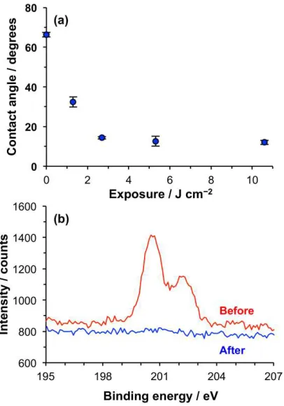
Figure 2. (a) Variation in the advancing water contact angle with UV exposure for CMPTS
films. (b) XPS Cl2p spectra recorded before and after exposure of samples to 4 J cm–2 of UV
irradiation.
A detailed investigation of the mechanism of dehalogenation of CMPTS films was reported
[image:10.612.85.288.266.556.2]of films to UV light. To confirm that the dehalogenation reaction was occurring as required, the
change in contact angle was measured as a function of the UV exposure (Figure 2a). The contact
angle of the virgin film was 68°, and this declined to 10° after an exposure of 2.7 J cm–2.
Thereafter, no significant change in contact angle was measured. XPS Cl2p spectra were
acquired before and after exposure of films to 4 J cm–2 of UV light (Figure 2b). It can be seen
that at this exposure, Cl is undetectable by XPS. An exposure of 4 J cm–2 was deemed suitable
for all of the subsequent patterning experiments.
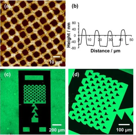
Figure 3. (a) AFM topographical image of a patterned POEGMEMA brush formed by UV
exposure of a CMPTS film through a mask, followed by ATRP. (b) Line section through (a).
(c,d) Fluorescence microscopy images of trap structures formed by photopatterning of CMPTS
combined with ATRP after immersion in a solution of GFP. GFP adsorbs to the carboxylic acid
terminated regions of the pattern formed by UV exposure (bright contrast) but not the
[image:11.612.84.320.266.499.2]Poly(oligo(ethylene glycol) methyl ether methacrylate) (POEGMEMA) brushes may be grown
from halogenated surfaces by ATRP to yield thick, highly protein-resistant surfaces.29, 31, 37
Growth is slower from chlorinated surfaces than from the more commonly used bromine
initiators,39 but is nevertheless substantial. Patterned brushes were fabricated by first exposing
CMPTS films to UV irradiation (4 J cm–2 at 244 nm) through a 2000 mesh electron microscope
grid, and then subsequently carrying out ATRP. Because a grid was used as a mask, a large
number of features were fabricated close together, enabling the uniformity of the patterning
process to be evaluated. Figure 3a shows an AFM tapping mode topographical image of a typical
sample. The dark squares correspond to regions that were exposed to UV light; here the Cl has
been removed by C-Cl bond photolysis and no polymer grows. The bars (bright contrast)
correspond to regions that were masked during UV exposure. Here polymer molecules have
grown from surface-immobilized Cl initiators. Line sections (Figure 3b shows a representative
example) indicated that the mean thickness of the brush layer, measured as the height difference
between the masked and exposed regions, was 104 nm.
To further test the effectiveness of the polymer patterning, samples were immersed in solutions
of green fluorescent protein (GFP). GFP is not expected to adsorb to POEGMEMA, which
exhibits strong resistance to protein adsorption,31, 40 but it is expected to adsorb to
POEGMEMA-free regions defined by dehalogenation of the CMPTS film. Figure 3c,d show fluorescence
microscopy images of a trap structure formed by UV exposure of CMPTS through a mask,
followed by ATRP of OEGMEMA and immersion in GFP solution. Dark contrast is observed
from regions that were masked during exposure (for example, the triangular features in Figure
difference between the masked and exposed regions is abrupt, indicating that the patterning has
been effective.
To achieve mobile SLBs of high quality, it is essential that there be low rates of polymer
growth from the exposed regions of the patterns. Because high molecular weights may be
achieved via ATRP, defects are effectively amplified. To assess polymer growth from residual
Cl ‘defects’ in the exposed regions, imaging secondary ion mass spectrometry (SIMS) was used
to characterize trap structures similar to the one in Figure 3c,d. SIMS enables retrospective mass
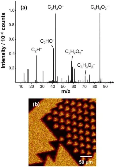
spectral imaging at high spatial resolution. Figure 4a shows a region of the negative ion SIMS
spectrum of an unpatterned POEGMEMA brush. The spectrum exhibits a plethora of
oxygen-containing fragment ions that may be used to differentiate the brush from the surrounding
surface. Patterned samples were imaged by mapping the intensity of the C2H3O– species (m/z
43). Figure 4b shows a secondary ion image formed for a trap structure similar to the one shown
in Figure 3c,d. The regions that exhibited dark contrast in Figure 3c,d are thought to be occupied
by polymer brushes, and this is confirmed by the C2H3O– image. In contrast, the SIMS image
exhibits dark contrast in regions corresponding to those that displayed bright contrast in Figure
3c,d. This confirms that the polymer is largely absent from the exposed regions of the sample; if
polymers are formed from low densities of Cl ‘defects’, they are present at levels too small to be
Figure 4. (a) Negative ion SIMS spectrum of an unpatterned POEGMEMA brush. (b) SIMS
image of a POEGMEMA trap structure formed by mapping the intensity of the C2H3O– species.
SLB Formation
To test the effectiveness of POEGMEMA as a means of confining SLBs, trap structures were
fabricated as described above and incubated in suspension containing vesicles formed using a
24.9:74.6:0.5 DOTAP:POPC:Atto590-DOPE mixture. The DOTAP is positively charged and is
expected to have a favorable electrostatic interaction with carboxylate groups formed at the
photo-modified CMPTS surface, aiding vesicle rupture.
To evaluate the efficacy of confinement of the SLB by the POEGMEMA brushes, trap
structures were formed and characterized by fluorescence microscopy after deposition of vesicles
(Figure 5a,b). It can be seen that the lipids are confined to the carboxylic acid terminated regions
formed during UV exposure: the pattern of fluorescence from the lipid layer in Figure 5a
[image:14.612.82.268.72.344.2](Figure 5b) displays a clear contrast difference between the triangular lipid-free regions (dark)
and the surrounding SLB (bright). These data confirm that POEGMEMA brushes resist the
formation of an SLB, and are a highly effective and convenient means to organize SLBs into
patterns.
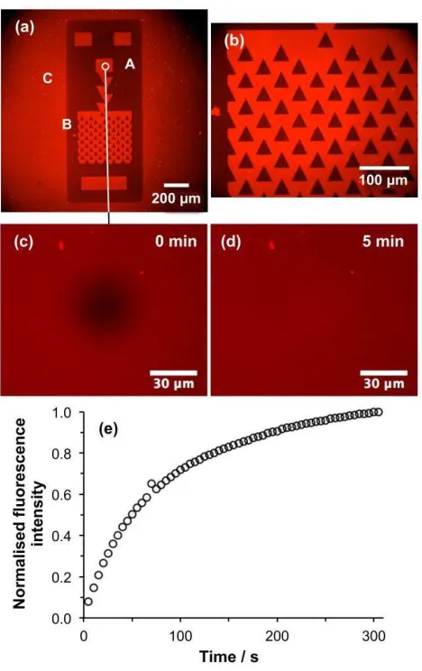
Figure 5. (a,b) Fluorescence micrographs of a trap structure formed by UV exposure of a
CMPTS film, ATRP of OEGMEMA and SLB deposition. Areas masked during UV light (for
example the region marked A in Fig5a) support growth of POEGMEMA by ATRP, and thus
resist SLB formation, while exposed regions such as B are polymer-free and facilitate SLB
formation. The laser spot used during patterning was somewhat larger than the dimensions of the
[image:15.612.84.318.180.552.2]outside the trap structure, enabling formation of an SLB there (eg. at C). (c) Fluorescence
micrograph showing a bleached spot formed in the small circular region identified in Figure 5a.
(d) Fluorescence micrograph of the same region acquired after 5 min. (e) Variation in
fluorescence intensity in the bleached region as a function of time after exposure.
FRAP measurements were made to test the mobility of lipids in these patterned bilayers.
Figure 5c shows a fluorescence micrograph acquired of a bleached spot (the dark, central feature
in the image) formed within the small circular region indicated in the upper central portion of
Figure 5a. Figure 5d shows a fluorescence micrograph of the same region acquired 5 min later. It
is clear that intensity has recovered fully in the bleached spot as a consequence of lipid diffusion
in the SLB. The fluorescence intensity in the bleached region is shown as a function of time in
Figure 5e. This fluorescence recovery plot was analyzed using the method of Axelrod et al. The
Axelrod method is a well-established method for the analysis of diffusion in supported lipid
bilayers. It involves fitting the recovery curve to yield a mathematical relationship between
fluorescence intensity and time after bleaching, from which the diffusion coefficient and mobile
fraction may be calculated.38 Analysis of the data n Figure 5e using this method indicated that
the mobile fraction was 98% and the diffusion coefficient was 0.84 m2 s–1, comparable to
values obtained for SLBs formed from the same lipids on glass. These data demonstrate that the
carboxylic acid functionalized surface produced by photochemical modification of the CMPTS
film is an excellent substrate for SLB formation.
Electrophoresis
Trap structures were defined by using mask-based photolithography to expose CMPTS films,
and the resulting carboxylic acid functionalized regions were enclosed by POEGMEMA by
incubation in Atto590-labelled DOTAP-POPC lipid vesicles, the sample was imaged using
fluorescence microscopy (Figure 6a). It may be seen that the fluorescence intensity is confined to
[image:17.612.84.319.156.470.2]the traps, and that it is uniformly distributed across their length.
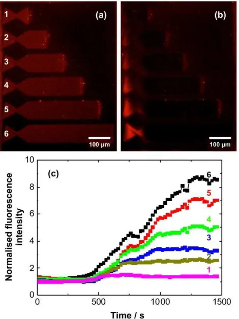
Figure 6. Fluorescence micrographs of trap structures before (a) and after application of a 100 V
dc potential for 20 min. (c) Time dependence of the fluorescence intensity measured at the
left-hand side of the trap structures in Figures 6a,b.
A 100 V dc potential was applied parallel to the long axes of the trap structures. After 20 min,
the distribution of fluorescence intensity was non-uniform. Intensity was found to have
accumulated in the ‘nest’ of the trap, at the left-hand side of the structures in Figure 6a,b. This is
consistent with movement of lipids opposite to the electric field direction. This movement of
(Figure 6c). Initially the fluorescence intensity changes slowly, but after 400 s, the intensity
starts to rise rapidly, indicating the presence of highly mobile lipids in the traps. The increase in
fluorescence intensity in the nest is proportional to the length of the trap, so the brightest
fluorescence is observed for the longest trap. The longest traps also require the longest time to
reach a limiting value, consistent with the fact that lipid transport occurs over longer distances.
For the shorter traps, a limiting intensity is reached much more quickly. The proportionality
between fluorescence intensity and trap length indicates that the charged fluorescent species are
mobile along the lengths of the traps.
Lipid diffusion in nanostructures
It is known that rates of diffusion of lipids in SLBs may be reduced when the bilayers are
formed into channels narrower than 50 nm.41-42 For example, Tsai et al used electron beam
lithography to fabricate barriers with periods of 125 and 250 nm, and containing gaps that varied
from 30 – 50 nm.42 They found that such structures were useful in capturing the diffusional
behavior of membrane lipids. To examine the feasibility of using polymer brushes for studies of
lipid diffusion in confined geometries, nanostructures were fabricated by interferometric
lithography (IL). A particularly attractive feature of IL for such studies is the fact that patterning
occurs simultaneously over a macroscopic region (~ 1 cm2 in the apparatus used here). Portions
of silicon wafer derivatized with a CMPTS film were placed in the interferometer and exposed to
UV light, before growth of polymer brushes by ATRP. In IL, the sample is exposed to an
interferogram with a sinusoidal cross-section; hence the resulting patterns exhibit a gradient
character because the intensity of illumination varies in a gradient fashion. Control of the
exposure conditions and development process (in this case, brush growth) provides control over
changing the angle between the sample and mirror in the interferometer, with a theoretical
minimum period of /2.
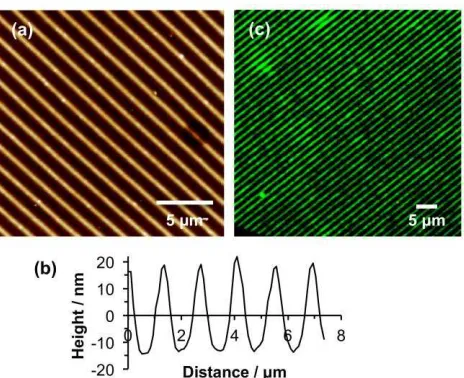
Figure 7. (a) AFM height image of POEGMEMA nanostructures formed by using IL to expose a
CMPTS film, followed by ATRP. (b) Line section through the height image in (a). (c)
Fluorescence microscopy image of the sample shown in (a) after immersion in a suspension of
Atto488-labelled vesicles.
Figure 7 shows an AFM topographical image of a nanostructured sample formed as described
above. The period was selected to be large (1.39 m) because it was intended to use fluorescence
microscopy to characterize the structure. The cross section reveals that the polymer structures
have a FWHM of 750 nm. The line section indicates that the polymer-free region, where the
CMPTS film was exposed to a maximum in the interferogram, has a width of 300 nm. To test
the effectiveness of these structures at confining vesicle deposition, fluorescence microscopy was
carried out after incubation of the sample with DOTAP:POPC:Atto488-DOPE vesicles. Very
narrow bands of fluorescence were observed (Figure 7c). The widths of these features are similar
[image:19.612.85.317.127.316.2]polymer-free regions observed in the AFM images. Clearly a precise estimation of the feature
sizes is not possible by fluorescence microscopy, but the data provide very good evidence that
nanostructured POEGMEMA brushes are effective at localizing vesicles in narrow regions.
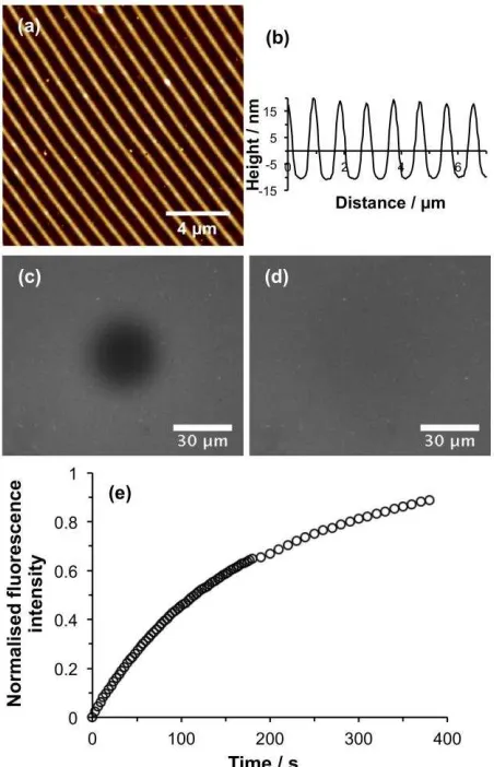
Figure 8. (a) AFM height image of POEGMEMA nanostructures formed by using IL to expose a
CMPTS film, followed by ATRP. (b) Line section through the height image in (a). (c)
Fluorescence microscopy image of the sample shown in (a) after deposition of an SLB and
photobleaching. (d) Fluorescence microscopy image acquired 375 s after photobleaching. (e)
Recovery in fluorescence as a function of time after photobleaching.
To determine whether the lipids in these structures remained mobile,
[image:20.612.83.309.155.506.2]nanostructured bilayers were investigated using FRAP. Figure 8a shows an AFM topographical
image of a nanostructured surface prior to SLB formation. The associated line section is shown
in Figure 8b. The period of the POEGMEMA nanolines was 926 nm, slightly smaller than the
period in Fig 7a, but the width of the polymer-free region was similar (300 nm). After
deposition of vesicles, lines of lipids could not be resolved because the microscope used for
FRAP measurements was fitted with a less powerful objective. After photobleaching, a dark,
spot was observed (Figure 8c). After 375 s, the fluorescence had recovered in the bleached
region, indicating that the lipids were mobile in the nanostructured channels formed between
POEGMEMA structures. Analysis of the fluorescence recovery curve (Figure 8e) yielded a
diffusion rate of 0.47 m2 s–1. Although this is smaller than the value measured for trap structures
such as the one in Figure 5, it remains within the range normally expected for mobile lipid
bilayers supported on glass substrates. Moreover, the mobile fraction was calculated to be 0.96,
indicating a fully mobile lipid bilayer. A systematic investigation of the relationship between
channel dimensions and diffusional behavior is beyond the scope of the present study. However,
the data presented here demonstrate that fabrication of polymer brush structures by IL is a
convenient and effective way of producing structures that facilitate uniform confinement of
SLBs over macroscopic areas.
CONCLUSIONS
Photolysis of C-Cl bonds in CMPTS films leads to the formation of carboxylic acid
functionalized surfaces. Mobile SLBs are formed on these surfaces. Unmodified regions of the
CMPTS film retain Cl, which is an initiator for ATRP. POEGMEMA brushes may be grown to
high thicknesses from these surfaces. The brushes resist the deposition of proteins, vesicles and
method to form patterned POEGMEMA brushes. These structures in turn provide a highly
effective means to organize the formation of supported lipid bilayers. The spatial confinement of
the bilayers is precise, and they exhibit similar mobilities to those observed for the same lipids
on glass surfaces. For both micrometer-scale and nanometer-scale structures the mobile fraction
is close to unity. While the mobility is slightly reduced in nanostructured channels, probably as a
consequence of the lateral confinement, it is still significant. This combination of patterning
approaches and surface initiated polymerization used here seems to be a promising approach for
the formation of spatially organized supported lipid bilayers.
AUTHOR INFORMATION
*Corresponding Author
E-mail: [email protected]
Present Addresses
†Department of Physics, University of Warwick, Gibbet Hill Road, Coventry, CV4 7AL UK.
ACKNOWLEDGEMENTS
The authors thank Dr P. Chapman for helpful contributions to the development of the
strategies described here, and Dr J. Roth for designing the traps that were used to generate the
data in Figure 6. The authors are grateful to EPSRC (Programme Grant EP/I012060/1) for
Financial Support. CNH gratefully acknowledges financial support from the Biotechnology and
Biological Sciences Research Council (BBSRC UK), award number BB/M000265/1. CNH was
also supported by Advanced Award 338895 from the European Research Council. This work
was also supported as part of the Photosynthetic Antenna Research Center (PARC), an Energy
Basic Energy Sciences under Award Number DE-SC 0001035. PARC’s role was to provide
partial support for CNH.
REFERENCES
1. Stryer, L., Biochemistry. 4th ed.; W. H. Freeman: New York, 1995.
2. Grzybowski, B. A.; Huck, W. T. S., The nanotechnology of life-inspired systems. Nat
Nano 2016, 11, 585-592.
3. Deng, N.-N.; Yelleswarapu, M.; Zheng, L.; Huck, W. T. S., Microfluidic Assembly of
Monodisperse Vesosomes as Artificial Cell Models. J. Am. Chem. Soc. 2017, 139, 587-590.
4. Citra, M. J.; Axelsen, P. H., Determination of molecular order in supported lipid
membranes by internal reflection Fourier transform infrared spectroscopy. Biophys. J. 1996, 71,
1796-1805.
5. Keller, C. A.; Glasmästar, K.; Zhdanov, V. P.; Kasemo, B., Formation of Supported
Membranes from Vesicles. Phys. Rev. Lett. 2000, 84, 5443-5446.
6. Tamm, L. K.; McConnell, H. M., Supported phospholipid bilayers. Biophys. J. 1985, 47,
105-113.
7. Richter, R. P.; Bérat, R.; Brisson, A. R., Formation of Solid-Supported Lipid Bilayers:
An Integrated View. Langmuir 2006, 22, 3497-3505.
8. Castellana, E. T.; Cremer, P. S., Solid supported lipid bilayers: From biophysical studies
9. Durfee, P. N.; Lin, Y.-S.; Dunphy, D. R.; Muñiz, A. J.; Butler, K. S.; Humphrey, K. R.;
Lokke, A. J.; Agola, J. O.; Chou, S. S.; Chen, I. M.; Wharton, W.; Townson, J. L.; Willman, C.
L.; Brinker, C. J., Mesoporous Silica Nanoparticle-Supported Lipid Bilayers (Protocells) for
Active Targeting and Delivery to Individual Leukemia Cells. ACS Nano 2016, 10, 8325-8345.
10. Santonicola, M. G.; Memesa, M.; Meszynska, A.; Ma, Y.; Vancso, G. J., Surface-grafted
zwitterionic polymers as platforms for functional supported phospholipid membranes. Soft
Matter 2012, 8, 1556-1562.
11. Kowal, J.; Wu, D.; Mikhalevich, V.; Palivan, C. G.; Meier, W., Hybrid Polymer–Lipid
Films as Platforms for Directed Membrane Protein Insertion. Langmuir 2015, 31, 4868-4877.
12. Zhang, Y.; Inal, S.; Hsia, C.-Y.; Ferro, M.; Ferro, M.; Daniel, S.; Owens, R. M.,
Supported Lipid Bilayer Assembly on PEDOT:PSS Films and Transistors. Adv. Funct. Mater.
2016, 26, 7304-7313.
13. Beltramo, P. J.; Van Hooghten, R.; Vermant, J., Millimeter-area, free standing,
phospholipid bilayers. Soft Matter 2016, 12, 4324-4331.
14. Cartron, M. L.; Olsen, J. D.; Sener, M.; Jackson, P. J.; Brindley, A. A.; Qian, P.;
Dickman, M. J.; Leggett, G. J.; Schulten, K.; Neil Hunter, C., Integration of energy and electron
transfer processes in the photosynthetic membrane of Rhodobacter sphaeroides. Biochim.
Biophys. Acta (BBA) - Bioenergetics 2014, 1837, 1769-1780.
15. Kumar, S.; Cartron, M. L.; Mullin, N.; Qian, P.; Leggett, G. J.; Hunter, C. N.; Hobbs, J.
K., Direct Imaging of Protein Organization in an Intact Bacterial Organelle Using
16. DeMond, A. L.; Mossman, K. D.; Starr, T.; Dustin, M. L.; Groves, J. T., T Cell Receptor
Microcluster Transport through Molecular Mazes Reveals Mechanism of Translocation. Biophys.
J. 2008, 94, 3286-3292.
17. Hartman, N. C.; Nye, J. A.; Groves, J. T., Cluster size regulates protein sorting in the
immunological synapse. Proc. Natl. Acad. Sci. USA 2009, 106, 12729-12734.
18. DeMond, A. L.; Groves, J. T., Interrogating the T cell synapse with patterned surfaces
and photoactivated proteins. Current Op. Immunol. 2007, 19, 722-727.
19. Stelzle, M.; Miehlich, R.; Sackmann, E., Two-dimensional microelectrophoresis in
supported lipid bilayers. Biophys. J. 1992, 63, 1346-1354.
20. Yoshina-Ishii, C.; Boxer, S. G., Controlling Two-Dimensional Tethered Vesicle Motion
Using an Electric Field: Interplay of Electrophoresis and Electro-Osmosis. Langmuir 2006, 22,
2384-2391.
21. Cheetham, M. R.; Bramble, J. P.; McMillan, D. G. G.; Krzeminski, L.; Han, X.; Johnson,
B. R. G.; Bushby, R. J.; Olmsted, P. D.; Jeuken, L. J. C.; Marritt, S. J.; Butt, J. N.; Evans, S. D.,
Concentrating Membrane Proteins Using Asymmetric Traps and AC Electric Fields. J. Am.
Chem. Soc. 2011, 133, 6521-6524.
22. Cheetham, M. R.; Bramble, J. P.; McMillan, D. G. G.; Bushby, R. J.; Olmsted, P. D.;
Jeuken, L. J. C.; Evans, S. D., Manipulation and sorting of membrane proteins using patterned
diffusion-aided ratchets with AC fields in supported lipid bilayers. Soft Matter 2012, 8,
23. Han, X. J.; Achalkumar, A. S.; Bushby, R. J.; Evans, S. D., A Cholesterol-Based Tether
for Creating Photopatterned Lipid Membrane Arrays on both a Silica and Gold Surface. Chem.
Eur. J. 2009, 15, 6363-6370.
24. Roth, J. S.; Zhang, Y.; Bao, P.; Cheetham, M. R.; Han, X.; Evans, S. D., Optimization of
Brownian ratchets for the manipulation of charged components within supported lipid bilayers.
Appl. Phys. Lett. 2015, 106, 183703.
25. Sun, S.; Montague, M.; Critchley, K.; Chen, M.-S.; Dressick, W. J.; Evans, S. D.;
Leggett, G. J., Fabrication of Biological Nanostructures by Scanning Near-field
Photolithography of Chloromethylphenylsiloxane Monolayers. Nano Lett. 2006, 6, 29-33.
26. Patten, T. E.; Matyjaszewski, K., Atom Transfer Radical Polymerization and the
Synthesis of Polymeric Materials. Adv. Mater. 1998, 10, 901-915.
27. Matyjaszewski, K.; Xia, J., Atom Transfer Radical Polymerization. Chem. Rev. 2001,
101, 2921-2990.
28. Ma, H. W.; Hyun, J. H.; Stiller, P.; Chilkoti, A., “Non-Fouling” Oligo(ethylene glycol)-
Functionalized Polymer Brushes Synthesized by Surface-Initiated Atom Transfer Radical
Polymerization. Adv. Mater. 2004, 16, 338.
29. Ma, H.; Wells, M.; Jr., T. P. B.; Chilkoti, A., Surface initiated polymerization of
nonfouling polymer brushes of oligoethylene glycol methacrylate on gold. Adv. Funct. Mater.
30. Ma, H.; Textor, M.; Clark, R. L.; Chilkoti, A., Monitoring kinetics of surface initiated
atom transfer radical polymerization by quartz crystal microbalance with dissipation.
Biointerphases 2006, 1, 35-39.
31. Ma, H.; Li, D.; Sheng, X.; Zhao, B.; Chilkoti, A., Protein resistant polymer brushes on
silicon oxide by surface initiated atom transfer radical polymerization. Langmuir 2006, 22, 3751
-3756.
32. Feng, W.; Zhu, S.; Ishihara, K.; Brash, J. L., Adsorption of Fibrinogen and Lysozyme on
Silicon Grafted with Poly(2-methacryloyloxyethyl Phosphorylcholine) via Surface-Initiated
Atom Transfer Radical Polymerization. Langmuir 2005, 21, 5980-5987.
33. Feng, W.; Brash, J. L.; Zhu, S., Non-biofouling materials prepared by atom transfer
radical polymerization grafting of 2-methacryloloxyethyl phosphorylcholine: Separate effects of
graft density and chain length on protein repulsion. Biomaterials 2006, 27, 847-855.
34. Zhang, Z.; Chao, T.; Chen, S.; Jiang, S., Superlow Fouling Sulfobetaine and
Carboxybetaine Polymers on Glass Slides. Langmuir 2006, 22, 10072-10077.
35. Alswieleh, A. M.; Cheng, N.; Canton, I.; Ustbas, B.; Xue, X.; Ladmiral, V.; Xia, S.;
Ducker, R. E.; El Zubir, O.; Cartron, M. L.; Hunter, C. N.; Leggett, G. J.; Armes, S. P.,
Zwitterionic Poly(amino acid methacrylate) Brushes. J. Am. Chem. Soc. 2014, 136, 9404-9413.
36. Barbey, R.; Lavanant, L.; Paripovic, D.; Schüwer, N.; Sugnaux, C.; Tugulu, S.; Klok,
H.-A., Polymer Brushes via Surface-Initiated Controlled Radical Polymerization: Synthesis,
37. Hucknall, A.; Rangarajan, S.; Chilkoti, A., In Pursuit of Zero: Polymer Brushes that
Resist the Adsorption of Proteins. Adv. Mater. 2009, 21, 2441-2446.
38. Axelrod, D.; Koppel, D. E.; Schlessinger, J.; Elson, E.; Webb, W. W., Mobility
measurement by analysis of fluorescence photobleaching recovery kinetics. Biophys. J. 1976, 16,
1055-1069.
39. Alang Ahmad, S. A.; Leggett, G. J.; Hucknall, A.; Chilkoti, A., Micro- and
Nanostructured Poly[oligo(ethylene glycol)methacrylate] Brushes Grown From Photopatterned
Halogen Initiators by Atom Transfer Radical Polymerization. Biointerphases 2011, 6, 8-15.
40. Hucknall, A.; Kim, D. H.; Rangarajan, S.; Hill, R. T.; Reichert, W. M.; Chilkoti, A.,
Simple Fabrication of Antibody Microarrays on Nonfouling Polymer Brushes with Femtomolar
Sensitivity for Protein Analytes in Serum and Blood. Adv. Mater. 2009, 21, 1968-1971.
41. Heath, G. R.; Roth, J.; Connell, S. D.; Evans, S. D., Diffusion in Low-Dimensional Lipid
Membranes. Nano Lett. 2014, 14, 5984-5988.
42. Tsai, J.; Sun, E.; Gao, Y.; Hone, J. C.; Kam, L. C., Non-Brownian Diffusion of