City, University of London Institutional Repository
Citation
:
Li, S., Fairbank, M., Fu, X., Wunsch, D. C. and Alonso, E. (2013). Nested-Loop
Neural Network Vector Control of Permanent Magnet Synchronous Motors. In: India
Conference, 2008. INDICON 2008. Annual IEEE. (pp. 81-86). IEEE. ISBN
978-1-4673-6128-6
This is the accepted version of the paper.
This version of the publication may differ from the final published
version.
Permanent repository link:
http://openaccess.city.ac.uk/5199/
Link to published version
:
Copyright and reuse:
City Research Online aims to make research
outputs of City, University of London available to a wider audience.
Copyright and Moral Rights remain with the author(s) and/or copyright
holders. URLs from City Research Online may be freely distributed and
linked to.
City Research Online:
http://openaccess.city.ac.uk/
[email protected]
Abstract -- With the improvement of battery technology over the past two decades and automotive technology advances, more and more vehicle manufacturers have joined in the race to produce new generation of affordable, high-performance electric drive vehicles (EDVs). Permanent magnet synchronous motors (PMSMs) are at the top of AC motors in high performance drive systems for EDVs. Traditionally, A PMSM is controlled with standard decoupled d-q vector control mechanisms. However, recent studies indicate that such mechanisms show limitations. This paper investigates how to mitigate such problems using a nested-loop recurrent neural network architecture to control a PMSM. The neural networks are trained using backpropagation through time to implement a dynamic programming (DP) algorithm. The performance of the neural controller is studied for typical vector control conditions and compared with conventional vector control methods, which demonstrates the neural vector control strategy proposed in this paper is effective. Even in a highly dynamic switching environment, the neural vector controller shows strong ability to trace rapidly changing reference commands, tolerate system disturbances, and satisfy control requirements for complex EDV drive needs.
Index Terms – Permanent magnet synchronous motor, decoupled
vector control, electric drive vehicle, recurrent neural network, dynamic programming, backpropagation through time
I. INTRODUCTION
MALLER, lighter, and less expensive electric motors are critical for the adoption of electric drive vehicles (EDVs) in significant quantities, especially for HEV and PHEV applications where motors have to be packaged in a vehicle along with other large powertrain components such as engines and transmissions [1]. Permanent magnet synchronous motors (PMSMs) have emerged in recent years as a very strong contender to replace induction motors used in electronically controlled variable speed applications. In most cases, PMSMs can provide superior performance in terms of increased
This work was supported in part by the U.S. National Science Foundation under Grant EECS 1059265/1102159, the Mary K. Finley Missouri Endowment, and the Missouri S&T Intelligent Systems Center.
Shuhui Li and Xingang Fu are with the Department of Electrical & Computer Engineering, The University of Alabama, Tuscaloosa, AL 35487, USA (email: [email protected]).
Michael Fairbank and Eduardo Alonso are with the School of Informatics, City University London, UK (email: [email protected], [email protected]).
Donald C. Wunsch, the Mary K. Finley Missouri Endowment professor, is with the Department of Electrical & Computer Engineering, Missouri University of Science and Technology, Rolla, MO 65409-0040, USA (email: [email protected]).
efficiency and reduced noise, while the total cost differential for motor plus power converters is subject to relatively fast payback [2, 3].
But, the performance of a PMSM depends also on how it is controlled. Conventionally, a PMSM is controlled using the standard decoupled d-q vector control approach [5-8]. But, recent studies indicate that the conventional vector control strategy is inherently limited [9, 10], particularly when facing uncertainties [11]. In recent years, significant research has been conducted in the area of dynamic programming (DP) for optimal control of nonlinear systems [16-20]. Classical DP methods discretize the state space and directly compare the costs associated with all feasible trajectories that satisfy the principle of optimality, guaranteeing the solution of the optimal control problem [21]. Adaptive critic designs constitute a class of approximate dynamic programming (ADP) methods that use incremental optimization combined with parametric structures that approximate the optimal cost and the control [22, 23]. Both classical DP and ADP methods have been used to train neural networks for a large number of nonlinear control applications, such as steering and controlling the speed of a two-axle vehicle [24], intercepting an agile missile [25], performing auto landing and control of an aircraft [26-28], and controlling a turbogenerator [29]. However, no research has been conducted regarding the vector control of PMSMs using DP or ADP-based neural networks.
The purpose of this paper is to report our research in developing a nested-loop neural-network-based vector control strategy for a PMSM. First, a brief review of the PMSM configuration in an electric drive vehicle is presented in Section II. Section III discusses PMSM model and the limitations associated with the conventional standard vector control method. Section IV proposes a nested-loop neural network vector control structure. Section V explains how to employ dynamic programming to train the current- and speed-loop neural networks for a PMSM. The performance of the proposed nested-loop neural network vector control scheme is evaluated in Section VI. Finally, the paper concludes with a summary of the main points.
II. PERMANENT MAGNET SYNCHRONOUS MOTORS IN
ELECTRIC DRIVE VEHICLES
A PMSM is an ac electric motor that uses permanent magnets to produce the air gap magnetic field rather than using electromagnets. The rotors are driven by the stators via a synchronous rotational field generated by the three-phase currents passing through the stator windings. In most EDV
Vector Control of Permanent Magnet Synchronous Motor
using Adaptive Recurrent Neural Networks
Shuhui Li, Michael Fairbank, Xingang Fu, Donald C. Wunsch, and Eduardo Alonso
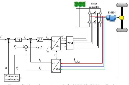
applications, the stator windings of a PM motor are connected to the dc bus through a standard three-leg voltage-source PWM converter (Fig. 1) [12, 13]. The converter converts dc to phase ac in the PMSM drive mode or converts three-phase ac to dc in the regenerating mode. In the drive mode, power flows from the dc bus to the PMSM to drive the vehicle while in the regenerating mode, power flows from the PMSM to the dc bus to charge the battery.
PWM
Position and speed sensing
P I
e
*
sq
v *
, ,
a b c
v
*
d
i
*
q
i
d
i q i
d,q a,b,c
, ,
a b c
i
d,q a,b,c
P I
*
sd
v P I
* n
n
Battery dc/ac converter
[image:3.612.53.300.151.314.2]PMSM
Fig. 1. Configuration and control of a PMSM in EDV application
A typical PMSM control strategy is the standard d-q vector control approach (Fig. 1), in which each of the d- and q-axis control loops has a cascaded structure: a fast inner current loop combined with an outer slower loop for speed and air gap
magnetic field controls. In Fig. 1, the speed reference m* is
generated during the operation of the vehicle. The speed and magnetic field control is converted into decoupled d-q current control. The current-loop controller implements the final control function by applying a stator voltage control signal to the voltage-source PWM converter to realize the variable-speed operation of the EDV. [14, 15].
The control signal applied directly to the power converter is a three-phase sinusoidal voltage having the stator current frequency of the PMSM. The general strategy for transformation from the d-q control signal to the three-phase
sinusoidal signal is also illustrated in Fig. 1 [15], in which vsd*
and vsq* are d- and q-axis output voltages generated by the
PMSM controller. The two d- and q-axis voltages are then
converted to the three-phase sinusoidal voltage signals, va*, vb*
and vc*, to control the voltage-source converter. Hence, from
the converter average model standpoint, the three-phase
sinusoidal voltage, vsa, vsb, and vsc, applied to the stator is
linearly proportional to the three-phase control voltage in the converter linear modulation mode [15].
III. PMSMCONVENTIONAL VECTOR CONTROL
A. PM Motor Model
A commonly used PMSM transient model is the Park model. Using the motor convention, space vector theory yields the stator voltage equation in the form [20]:
0 1 1 0
sd sd sd sd
s e
sq sq sq sq
v i d
R
v i dt
(1)
where Rsis the resistance of the stator winding;e is the motor
electrical rotational speed; and vsd, vsq, isd, isqsd,and sqare
the d and q components of instant stator voltage, current, and flux. If the d-axis is aligned along the rotor flux position, the stator flux linkages are
0
0 0
sd ls dm sd f
sq ls qm sq
L L i
L L i
(2)
where Lls is the leakage inductance of the stator winding; Ldm
and Lqm are the stator and rotor d- and q-axis mutual
inductances; fis the flux linkage produced by the permanent
magnet. Under the steady-state condition, (1) reduces to
0
sd s e q sd
sq e d s sq e f
V R L I
V L R I
(3)
If neglecting stator winding resistance, the stator d and q-axis currents are
,
sq sd e q sd sq e f e d
I V
L I V
L (4)In a PM motor, the magnets can be placed in two different ways on the rotor. Depending on the placement they are called either as surface permanent magnet (SPM) motor or interior permanent magnet (IPM) motor. An IPM motor is considered to have saliency with q axis inductance greater than the d axis
inductance (Lq > Ld) while a SPM motor is considered to have
small saliency, thus having practically equal inductances in
both axes (Lq=Ld) [8]. Therefore, depending on SPM or IPM
motor, the torque of the PM motor is calculated by (5) or (6)
em p f sqi SPM motor
(5)
em p f aqi Ld L i iq ad aq IPM Motor
(6)where p is pole pairs. If the torque computed from (5) or (6) is positive, the PM motor operates in the drive mode. Otherwise, the motor operates in the regenerate mode.
B. EDV Drives Model
In an electric drive vehicle, the motor produces an electromagnetic torque. The bearing friction and wind resistance (drag) can be combined with the load torque opposing the rotation of the PM motor. The net torque, the
difference between the electromagnetic torque em developed
by the motor and the load torque TL causes the combined
inertias Jeq of the motor and the load to accelerate. Therefore,
using the motor convention, the rotational speed of the motor follows from
m
em eq a m L
d
J B T
dt
(7)
where m is the motor rotational speed, and Bais the active
damping coefficient representing motor rotational losses. The
relation between m and e is presented in (8), where p is
motor pole pairs.
e p m
(8)C. Conventional PM Motor Vector Control
speed-loop controller is normally a PI controller that is designed based on the torque equation (7). The current-loop controller is developed by rewriting (1) and (2) as
sd
sd s sd d e q sq
di
v R i L L i
dt
(9)
sq
sq s sq q e d sd e f
di
v R i L L i
dt
(10)
where the item in the bracket of (9) and (10) is treated as the state equation between the voltage and current in the d- or q-axis loops, and the other items are treated as compensation
terms [12, 25]. This treatment assumes that vsd in (9) has no
major influence on isq and vsqin (10) has no main effect on isd.
But, this assumption is inadequate as explained below.
According to Fig. 1, the final control voltages vsd* and vsq*,
linearly proportional to the converter output voltages vsd and
vsq [25], include the d- and q-axis voltages vsd’ and vsq’
generated by the current-loop controllers plus the
compensation terms as shown by (11). Hence, the
conventional control configuration intends to regulate isdand
isq using vsd
’
and vsq
’
, respectively. But, according to (4), the
d-axis voltage is primarily effective for isq or toque control, and
the q-axis voltage is mainly effective for isd control.
* '
* '
sd sd e q sq
sq sq e d sd e f
v v L i
v v L i
(11)
IV. PMSMVECTOR CONTROL USING ARTIFICIAL NEURAL
NETWORKS
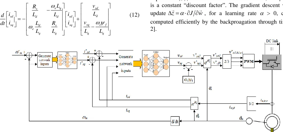
The neural network control scheme consists of a faster inner current-loop neural network controller plus a slower outer speed-loop neural network controller as shown by Fig. 2.
A. Current-Loop Neural Network Vector Control
To develop a current-loop neural network vector controller, the PM motor model of eq. (1) is rearranged into the standard state-space form as shown by:
e q sd
s
d
sd d d sd
sq e f
sq d s sq
e
q q q q
L v
R
L
i L L i
d
v
i L R i
dt
L L L L
(12)
where the system statesare isdand isq, permanent magnet flux
f is normally constant, and converter output voltages vsdand
vsq are proportional to the control voltage of the action neural
network. For digital control implementation, the discrete equivalent of the continuous system state-space model must be obtained as shown by:
sd s s sd s sd s
sq s s sq s sq s e f
i kT T i kT v kT
i kT T i kT v kT
A B (13)
where Ts represents the sampling period, A is the system
matrix, and B is the input matrix. In this paper, a
zero-order-hold discrete equivalent mechanism [31] is used to convert the continuous state-space model of the system (14) to the discrete
state-space model (13). We used Ts=0.001sec in all
experiments.
Let sd , sd , and 0 .
sq sq e f
i v
x u k
i v
Then, the state
equation (13) can be simplified in a more general form as shown by
1
t t t
x Ax B u k (14)
The system is controlled by the action network
x p, x z, i
which is a neural network with weight vector zi, such that
, ,
t t t t i
u
x p x z (15)The objective of the current-loop neural controller is to
implement a current tracking problem, i.e. hold the state xt
near to a given (possibly moving) target state pt. We train the
weights of the action network to solve the tracking problem by
doing gradient descent with respect to won the following
function based on the dynamic programming principle:
0,
m t
i t t
t
J x z
x p (16)where m is some constant power (we used m=0.5 in our
experiments), || denotes the modulus of a vector, and [0, 1]
is a constant “discount factor”. The gradient descent weight
update z
J w, for a learning rate > 0, can be [image:4.612.56.538.495.720.2]computed efficiently by the backproagation through time [1, 2].
In addition, to overcome the challenge of training the action network for rapidly changing target states and random variation of PM motor parameters in EDV applications, we have employed the following strategies: 1) a “stabilizing matrix” approach to enhance the learning speed and stability of the neural network controller and 2) a design of using predicted and past inputs to allow the neural network having the capability of training offline but adaptive online [XX].
With the stabilizing matrix [XX], the control voltage from the current-loop action network becomes
, ,
0t t t t i t
u x p x z Wx k (17)
where W0 B1
A I
is constant. It acts like an extraweight matrix in the neural network that connects the input layer directly to the output layer.
To make the neural network having the capability of training offline but adaptive online, the neural network needs to have some idea on how the actual plant behavior is differing from its expected behavior. Hence we give the neural network an extra input of the difference between the actual current
state
xt and the predicted current state
xˆt calculated witha fixed model
0 1 0 1
ˆt t t
x A x B u k
(18)
where A0 and B0 are constant matrices of (13) chosen for the
default normal PMSM parameters. This idea is similar to the conventional predictive control concept. However, when the predictive input is combined with the neural network, it is much more powerful than the conventional only model-based predictive control mechanism.
Finally to improve performance further, the neural network needs to know what action it attempted in the previous time step. This enables the neural network to get feedback on what it tried previously and hence whether it’s worth trying that a bit more next time, or a bit less. So, we add a network input
which represents the previous action, i.e. ut1.
In summary, with the stabilizing matrix and predicted and past inputs to the network, the control voltage generated by the current-loop action network becomes
, , ˆ, 1,
0t t t t t t t i t
u x p x x x u z Wx k (19)
B. Speed-Loop Neural Network Controller
To develop a speed-loop neural network controller, the torque equation from Eq. (7) is rearranged into the standard state-space representation as shown by:
1
m a
m em L
eq eq
d B
T
dt J J
(20)
where the system state is m and the drive torque em is
proportional to the output of the speed-loop action neural network. The conversion from the torque to the q-axis current is obtained from Eq. (5). For digital control implementation, the discrete equivalent of the continuous state-space model must be obtained as shown by
m kTs Ts a m kTs b em kTs TL
(21)The objective of the speed-loop control is to implement a
speed tracking problem, i.e. hold the state m near to a given
(possibly moving) target state m*. We train the weights of the
speed-loop action network to solve the tracking problem by
doing gradient descent with respect to wson the following
function based on the dynamic programming principle:
*0,
n t
m s s mt mt
t
J
z
(22)We also adopted the stabilizing matrix strategy, the predictive input, and the previous control action for the speed-loop neural network controller. Therefore, the control signal generated by the speed-loop action network is
*
_ ( 1)
0
ˆ
, , , ,
em t mt mt mt mt mt em t s
s mt L
z
T
W
(23)
In (23), the predictive input is
0 ( 1) 0 ( 1)
ˆmt a m t b em t TL
(24)
where a0 and b0 are constant values of (21) chosen for the
default PM motor inertias and damping coefficient.
V. TRAINING NEURAL NETWORKS BASED UPON DYNAMIC
PROGRAMMING
Dynamic programming employs the principle of optimality and is a very useful tool for solving optimization and optimal control problems. According to [20], the principle of optimality is expressed as: “An optimal policy has the property that whatever the initial state and initial decision are, the remaining decisions must constitute an optimal policy with regard to the state resulting from the first decision.” The typical structure of the time DP includes a discrete-time system model and a performance index or cost associated with the system [23].
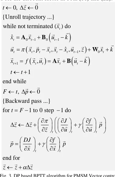
A. Backpropagation Through Time Algorithm
For the PM motor drives, the current- and speed-loop action neural networks were trained separately to minimize the DP cost of Eqs. (16) and (22), respectively, by using the backpropagation through time (BPTT) algorithm [33]. BPTT
is gradient descent onJ x z
0,
orJ
m0,zs
with respect tothe weight vector of the action network. BPTT can be applied
to an arbitrary trajectory with an initial statex0or
m0,anda vector argument gives a matrix, such that for example
(dA/dw)ij=dAj/dwi. In Fig. 3, the subscripted k variables on parentheses indicate that a quantity is to be evaluated at time step k. For the termination condition of a trajectory, we used a fixed trajectory length corresponding to a real time of 1
second (i.e. a trajectory had 1/Ts=1000 time steps in it). We
used =1 for the discount factor in both (16) and (22).
0 1 0 1
1 0
1
0, 0 {Unroll trajectory ...} while not terminated ( ) do
ˆ
ˆ , , , , ,
1 end while
, 0 {
t
t t t
t t t t t t t t
t t t t t
t z
x
x x u k
u x p x x x u z x k
x f x u x u k
t t
F t p
A B
W
A B
Backward pass ...} for 1 to 0 step 1 do
end for
t t t
t t
t F
J f
z z p
z u u
DJ f
p p
x x
z z z
[image:6.612.78.267.130.419.2]
Fig. 3. DP based BPTT algorithm for PMSM Vector control
B. Training the Current-Loop Neural Controller
To train the current-loop neural network controller, the system data associated with Eq. (12) are specified. The training procedure for the current-loop neural network controller includes 1) randomly generating a sample initial
state isdq(j), 2) randomly generating a changing sample
reference dq current time sequence, 3) unrolling the trajectory of the GCC system from the initial state, 4) training the current-loop neural network based on the DP cost function Eq. (16) and the BPTT training algorithm, and 5) repeating the process for all the sample initial states and reference dq currents until a stop criterion associated with the DP cost is reached (Fig. 3). The weights were initially all randomized using a Gaussian distribution with zero mean and 0.1 variance. The training also considers variable nature of the PM motor resistance and inductance. Training used RPROP [35] to accelerate learning, and we allowed RPROP to act on multiple trajectories simultaneously (each with a different start point
and isdq*).
The generation of the reference current must consider the physical constraints of a practical PMSM. These include the rated current and converter PWM saturation constraints. From the neural network standpoint, the PWM saturation constraint stands for the maximum positive or negative voltage that the action network can output. Therefore, if a reference dq current requires a control voltage that is beyond the acceptable voltage
range of the action network, it is impossible to reduce the cost (Eq. (16)) during the training of the action network.
The following two strategies are used to adjust randomly generated reference currents. If the rated current constraint is exceeded, the reference dq current is modified by keeping the
q-axis current reference isq* unchanged to maintain torque
control effectiveness (Eq. (5)) while modifying the d-axis
current reference isd* to satisfy the d-axis control demand as
much as possible as shown by [13, 14]
2 2* * * *
_ sign _ max
sd new sd sdq sq
i i i i (22)
If the PWM saturation limit is exceeded, the reference dq current is modified by
2 2
* * * * *
_ max
* *
sd sq e q sq sdq sd
sd sq e f e d
v i L v v v
i v L
(23)
which represents a condition of keeping the d-axis voltage
reference vsd* unchanged so as to maintain the torque control
effectiveness ((4) and (5)) while modifying the q-axis voltage
reference vsq* to meet the d-axis control demand as much as
possible [13]
.
C. Training the Speed-Loop Neural Network Controller
To train the speed-loop neural network controller, the system data associated with Eq. (7) are specified [6, 7, 14]. The training procedure includes 1) randomly generating a
sample initial state m, 2) randomly generating a changing
sample reference speed time sequence, 3) unrolling the motor speed trajectory from the initial state, 4) training the neural network based on the DP cost function of Eq. (22) and the BPTT training algorithm, and 5) repeating the process for all the sample initial states and reference speeds until a stop criterion associated with the DP cost is reached. Training also used RPROP.
The generation of the reference speed considers the speed changing range from 0 rad/s to the maximum possible motor rotating speed. The training considers variable nature of the
inertia and the damping coefficient and the limitation of
maximum acceptable torque.
[image:6.612.316.560.539.627.2]Fig. 4. Average DP cost per trajectory time step for training neural controller
Figure 4 demonstrates the average DP cost per trajectory time step for a successful training of the current-loop action neural network, in which both the initial state is generated randomly using Gaussian distribution while the reference dq currents are generated randomly using uniform distribution. Each trajectory duration was unrolled during training for a duration of 1 second, and the reference dq current was changed every 0.05 seconds. As the figure indicates, the
0 100 200 300 400 500 101
102 103 104
A
ve
ra
ge
T
o
ta
l C
o
st
overall average DP cost dropped to a small number quickly, demonstrating good learning ability of the neural controller for the vector control application.
VI. PERFORMANCE EVALUATION OF NESTED-LOOP NEURAL
NETWORK CONTROLLER
[image:7.612.313.560.79.396.2]To evaluate the current- and speed-loop neural network controllers, an integrated transient simulation of a complete PMSM system is developed by using power converter average and detailed switching models in SimPowerSystems (Fig. 5), in which both steady and variable drive conditions are considered. The average model is used for an initial evaluation while the detailed switching model is used for investigation under more practical conditions. For the switching-model based PMSM system, the converter switching frequency is 1980Hz and losses within the dc/ac power converter are considered. The parameters used in the simulation study are shown in Table 1.
Fig. 5. Neural network control of PM motor in SimPowerSystems
Parameter Value Units
Rated Power 50 kW
dc voltage 500 V
Permanent magnet flux 0.1757 wb
Inductance in q-axis, Lq 1.598 mH
Inductance in d-axis, Ld 1.598 mH
Stator copper resistance, Rs 0.0065 Ω
Inertia 0.089 kgm2
Damping coefficient 0.1
Pole pairs 4
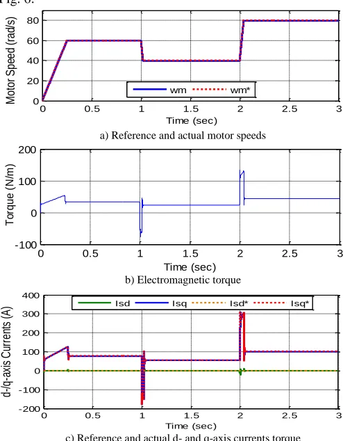
A. Ability of the Neural Network Controllers in Current and Speed Tracking
Figure 6 presents a performance study of the current- and speed-loop controllers of the PM motor under a steady load torque condition by using the average-model based simulation. The motor starts with a reference speed increasing linearly from 0 rad/s at the beginning to 60 rad/s at t=0.25s. This causes the q-axis reference current generated by the speed-loop controller increasing linearly while d-axis reference current is hold at 0A for a minimum stator current control purpose. As shown by Fig. 6, both motor current and speed can follow the reference current and speed perfectly. When the reference speed changes to a constant value of 60 rad/s at t=0.25s, the motor current or torque is quickly regulated in such a way that makes the motor get to the steady speed almost immediately. For other reference speed change from 60 rad/s to 40 rad/s at t=1s and from 40 rad/s to 80 rad/s at t=2s, the nested-loop neural network controller has excellent
performance in regulating current, torque, and speed of the PM motor to meet the motor control demands as shown by Fig. 6.
a) Reference and actual motor speeds
b) Electromagnetic torque
[image:7.612.50.297.276.369.2]c) Reference and actual d- and q-axis currents torque Fig. 6. Performance of nested-loop neural network vector controller
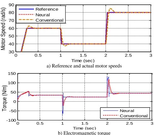
B. Comparison of Neural Network Controller with Conventional Vector Control Method
For the comparison study, the current- and speed-loop PI controllers are designed by using the conventional standard vector control technique, as shown in Section III. The gains of the current-loop PI controller are designed based on the transfer function of Eqs. (9) and (10) [7]. The gains of the speed-loop PI controller are designed based on the transfer function of Eq. (7). Then, for digital control implementation of
the PI controllers at the sampling rate of Ts=1ms, the
controller gains for both the speed and current loops are retuned until the controller performance is acceptable [14]. Tuning of the PI controllers is a challenging task, particularly
for a low sampling rate, such as Ts=1ms. This gives neural
network controller better a advantage from this perspective. The figure indicates that the neural network controller has the fastest response time, low overshoot, and best performance. For many other reference current conditions, the comparison demonstrates that the neural network vector controller performs better.
C. Performance Evaluation under Variable Parameters of a PM Motor
PM motor stability has been one of the main issues to be investigated. In general, such a study primarily focuses on the motor performance under uncertain system parameter variations. These include changes of motor resistance and
0 0.5 1 1.5 2 2.5 3
0 20 40 60 80
Mot
or
S
pe
ed
(rad
/s)
Time (sec)
wm wm*
0 0.5 1 1.5 2 2.5 3
-100 0 100 200
T
or
q
u
e
(N
/m
)
Time (sec)
0 0.5 1 1.5 2 2.5 3
-200 -100 0 100 200 300 400
d-/q
-a
xi
s
C
ur
re
nt
s
(A
)
Time (sec)
[image:7.612.51.299.390.517.2]inductance from its normal values or changes of fraction coefficient and combined inertia. Those changes would affect the performance of the current- or speed-loop controller.
a) Reference and actual motor speeds
[image:8.612.49.294.84.300.2]b) Electromagnetic torque
Fig. 7. Comparison of conventional and neural vector controllers
In this paper, the nested-loop neural network control technique is evaluated for two variable system parameter conditions, namely, 1) variation of motor resistance and inductance, and 2) deviation of motor drive parameters associated with the torque-speed equation (7). Figure 8 shows how the neural network controllers are affected when the motor resistance and inductance values increase by 30% from
the initial values and the equivalent inertia Jeqis doubled. The
study shows that both the current- and speed-loop neural network controllers are affected very little by the system parameter variation. This is due to the fact that both the speed- and current-loop neural network controllers have been trained for the variable system parameter conditions so that the neural network controllers possess an ability to handle the motor control under variable system parameter conditions.
a) Motor speed
[image:8.612.313.562.217.544.2]
b) d-/q-axis currents
Fig. 8. Performance of neural vector controllers under variable system parameter conditions
D. Performance Evaluation in Power Converter Switching Environment
In reality, the PM motor control is achieved through power electronic converters which operate in a highly dynamic switching environment (Fig. 5). This causes high order harmonics in the three-phase PMSM stator voltage and current. This means that in the dq reference frame, large oscillations
would appear in voltage vsdq and current isdq . Since those
oscillation impacts are not considered during the network training stage, the neural network controller could be severely deteriorated or loss stability. Hence, it is important to investigate the behavior of the neural network controller in the power converter switching environment.
a) Reference and actual motor speed
b) d-/q-axis currents
b) Three-phase stator current
Fig. 9. Performance of nested-loop neural network controller in power converter switching environment
Figure 9 presents a case study of neural network vector controller in the switching environment of the power converter, in which the speed reference is similar to those used in Fig. 6. As it can be seen from the figure, the neural network control shows an excellent performance in the high frequency switching condition too. Due to the switching impact, the actual dq current oscillates around the reference current. An examination of the stator current shows that the three-phase current is very balanced and adequate (Fig. 9c). For any command change of the reference speed, the motor can be adjusted to a new balanced three-phase current and a new speed quickly, demonstrating a strong optimal control capability of the neural network vector control method even in the highly dynamic switching condition.
0 0.5 1 1.5 2 2.5 3
30 40 50 60 70 80 90 M o to r S pe e d (r ad /s ) Time (sec) Reference Neural Conventional
0 0.5 1 1.5 2 2.5 3
-100 -50 0 50 100 150 T or qu e (N /m ) Time (sec) Neural Conventional
0 0.5 1 1.5 2 2.5 3
0 20 40 60 80 M o to r S pe e d (r ad /s ) Time (sec) wm wm*
0 0.5 1 1.5 2 2.5 3
-500 -250 0 250 500 d /q -a xi s cu rr e n t ( A ) Time (sec) Isd Isq Isd* Isq*
0 0.5 1 1.5 2 2.5 3 0 20 40 60 80 M o to r S p e e d ( ra d /s ) Time (sec) wm wm*
0 0.5 1 1.5 2 2.5 3
-400 -200 0 200 400 600 d-/q -a xi s cu rr en t ( A ) Time (sec)
Isd Isq Isd* Isq*
1.9 1.95 2 2.05 2.1 2.15 2.2
[image:8.612.51.297.503.709.2]VII. CONCLUSIONS
Permanent magnet synchronous motors are used widely in electric drive applications, particularly in electric drive vehicles. This paper investigates the conventional standard vector control approach for the PMSM and analyzes the limitations associated with conventional vector control method. Then, a nested-loop neural network based vector control method is proposed. The paper describes how dynamic-programming (DP) methods are employed to train the current- and speed-loop neural network controllers through a backpropagation through time algorithm.
The performance evaluation demonstrates that the current-loop neural network controller can track the reference d- and q-axis currents effectively while the speed-loop neural network controller is able to follow the reference speed excellently. Compared to the conventional standard vector control method, the neural network vector control approach produces the fastest response time, low overshoot, and, in general, the best performance. In addition, since the neural networks are trained under variable system parameters, the nested-loop neural network controller has more attractive performance when the system parameters are hard to be identified.
In a highly dynamic switching environment, the neural vector controller again demonstrates strong capability in tracking reference commands while maintaining a high power quality.
VIII. REFERENCE
[1] E. Figueres, G. Garcera, J. Sandia, F. Gonzalez-Espin, and J.C. Rubio, “Sensitivity Study of the Dynamics of Three-Phase Photovoltaic Inverters With an LCL Grid Filter,” IEEE Transactions on Industrial Electronics, Vol. 56, No. 3, March 2009, pp. 706-717. [2] C. Wang, and M.H. Nehrir, “Short-Time Overloading Capability and
Distributed Generation Applications of Solid Oxide Fuel Cells,” IEEE Trans. on Energy Conversion, Vol. 22, No. 4, Nov. 2007, pp. 898-906. [3] A. Luo, C. Tang, Z. Shuai, J. Tang, X. Xu, and D. Chen, “Fuzzy-PI-Based Direct-Output-Voltage Control Strategy for the STATCOM Used in Utility Distribution Systems,” IEEE Transactions on Industrial Electronics, Vol. 56, No. 7, July 2009, pp. 2401-2411.
[4] J. M. Carrasco, L. G. Franquelo, J. T. Bialasiewicz, E. Galván, R. C. P. Guisado, M. Á. M. Prats, J. I. León, and N. Moreno-Alfonso, “Power-Electronic Systems for the Grid Integration of Renewable Energy Sources: A Survey,” IEEE Trans. On Industrial Electronics, Vol. 53, No. 4, August, 2006.
[5] L. Xu, and Y. Wang, “Dynamic Modeling and Control of DFIG Based Wind Turbines under Unbalanced Network Conditions”, IEEE Trans. on Power Systems, Vol. 22, No. 1, Feb. 2007.
[6] A. Mullane, G. Lightbody, and R. Yacamini, “Wind-Turbine Fault Ride-Through Enhancement,” IEEE Trans. on Power Systems, Vol. 20, No. 4, Nov. 2005.
[7] R. Pena, J.C. Clare, and G. M. Asher, “Doubly fed induction generator using back-to-back PWM converters and its application to variable speed wind-energy generation,” IEE Proc.-Electr. Power Appl., Vol. 143, No 3, May 1996, pp. 231-241.
[8] B. C. Rabelo, W. Hofmann, J. L. Silva, R. G. Oliveira, and S. R. Silva, “Reactive Power Control Design in Doubly Fed Induction Generators for Wind Turbines,” IEEE Transactions on Industrial Electronics, Vol. 56, No. 10, October 2009, pp. 4154-4162.
[9] S. Li and T.A. Haskew, “Transient and Steady-State Simulation of Decoupled d-q Vector Control in PWM Converter of Variable Speed Wind Turbines,” Proceedings of 33rd Annual Conference of IEEE Industrial Electronics (IECON 2007), Taipei, Taiwan, Nov. 5-8, 2007.
[10] S. Li and T.A. Haskew, “Analysis of Decoupled d-q Vector Control in DFIG Back-to-Back PWM Converter,” Proceedings of IEEE Power Engineering Society General Meeting, Tampa FL, June 24-28, 2007. [11] J. Dannehl, C. Wessels, and F. W. Fuchs, “Limitations of
Voltage-Oriented PI Current Control of Grid-Connected PWM Rectifiers With
LCL Filters,” IEEE Transactions on Industrial Electronics, Vol. 56, No. 2, October 2009, pp. 380-388
[12] I. Codd, “Windfarm Power Quality Monitoring and Output Comparison with EN50160”, Proc. of the 4th Intern. Workshop on Large-scale Integration of Wind Power and Transmission Networks for Offshore Wind Farm, 20-21 Oct. 2003, Sweden.
[13] B. I. Nass, T. M. Undeland, and T. Gjengedal, “Methods for Reduction of Voltage Unbalance in Weak Grids Connected to Wind Plants”,
Proc. of the IEEE Workshop on Wind Power and the Impacts on Power Systems, Oslo, June 2002.
[14] Shuhui Li, Timothy A Haskew, Yang-Ki Hong, and Ling Xu, “Direct-Current Vector Control of Three-Phase Grid-Connected Rectifier-Inverter,” Electric Power System Research (Elsevier), Vol. 81, Issue 2, February 2011, pp. 357-366.
[15] Shuhui Li, Tim Haskew, and Ling Xu, “Control of HVDC Light Systems using Conventional and Direct-Current Vector Control Approaches,” IEEE Transactions on Power Electronics, Vol. 25, No. 12, December 2010, pp. 3106-3118.
[16] A. Al-Tamimi, M. Abu-Khalaf, and F. L. Lewis, “Adaptive critic designs for discrete time zero-sum games with application to H` control,” IEEE Trans. Syst., Man, Cybern. B, vol. 37, no. 1, pp. 240– 247, Feb. 2007.
[17] S. N. Balakrishnan and V. Biega, “Adaptive-critic-based neural networks for aircraft optimal control,” J. Guid. Control Dyn., vol. 19, pp. 893–898, July 1996.
[18] S. N. Balakrishnan, J. Ding, and F. L. Lewis, “Issues on stability of ADP feedback controllers for dynamical systems,” IEEE Trans. Syst., Man., Cybern. B, vol. 38, no. 4, pp. 913–917, Aug. 2008.
[19] S. Mohahegi, G. K. Venayagamoorth, and R. G. Harley, “Adaptive critic design based neuro-fuzzy controller for a static compensator in a multimachine power system,” IEEE Trans. Power Syst., vol. 21, no. 4, pp. 1744–1754, Nov. 2006.
[20] R. E. Bellman, Dynamic Programming. Princeton, NJ: Princeton Univ. Press, 1957.
[21] Kirk, D. E., Optimal Control Theory: An Introduction, Prentice–Hall, Englewood Cliffs, NJ, 1970, Chaps. 1–3.
[22] D. V. Prokorov and D. C. Wunsch, “Adaptive Critic Designs,” IEEE Transactions on Neural Networks, Vol. 8, No. 5, 1997, pp. 997–1007. [23] F.Y. Wang, H. Zhang, and D. Liu, "Adaptive dynamic programming:
An introduction," IEEE Computational Intelligence Magazine, pages 39–47, 2009.
[24] G. G. Lendaris, L. Schultz, and T. T. Shannon, “Adaptive Critic Design for Intelligent Steering and Speed Control of a 2-Axle Vehicle,”
Proceedings of the 2000 International Joint Conference on Neural Networks, Como, Italy, July 2000.
[25] D. Han, and S. N. Balakrishnan, “Adaptive Critic Based Neural Networks for Control-Constrained Agile Missile Control,”
Proceedings of the American Control Conference, San Diego, USA, June 2 - 4, 1999, pp. 2600–2604.
[26] G. Saini, and S. N. Balakrishnan, “Adaptive Critic Based Neurocontroller for Autolanding of Aircraft,” Proceedings of the American Control Conference, Albuquerque, USA, June 4 - 6,1997, pp. 1081–1085.
[27] S. N. Balakrishnan and V. Biega, “Adaptive-Critic-Based Neural Networks for Aircraft Optimal Control,” Journal of Guidance, Control, and Dynamics, Vol. 19, No. 4, 1996, pp. 893–898.
[28] K. KrishnaKumar and J. Neidhoefer, “Immunized Adaptive Critics for Level-2 Intelligent Control,” Proceedings of the IEEE International Conference on Systems, Man and Cybernetics, Orlando, USA, Oct. 12 - 15,1997, pp. 856–861.
[29] Venayagamoorthy, G. K., Harley, R. G., and Wunsch, D. C., “Comparison of Heuristic Dynamic Programming and Dual Heuristic Programming Adaptive Critics for Neurocontrol of a Turbogenerator,”
[30] N. Mohan, T. M. Undeland, and W. P. Robbins, Power Electronics: Converters, Applications, and Design, 3rd Ed., John Wiley & Sons Inc.,
October 2002.
[31] Gene F. Franklin, J. David Powell, Michael L. Workman, " Digital control of dynamic systems," 3rd edition, Addison-Wesley, 1998. [32] Christopher M. Bishop, "Neural Networks for Pattern Recognition",
Oxford University Press, pages 55, 1995.
[33] Paul J. Werbos", "Backpropagation through time: What it does and how to do it", Proceedings of the IEEE, Vol. 78, No. 10, 1550-1560, 1990.
[34] Martin Riedmiller and Heinrich Braun, "A Direct Adaptive Method for Faster Backpropagation Learning: The RPROP algorithm", Proc. of the IEEE Intl. Conf. on Neural Networks", San Francisco, CA, pages 586--591, 1993.