Abstract— Tokamak is a magnetic confinement device that confines hot plasma in the shape of torus during the process of thermonuclear fusion power generation. In tokamak, eddy currents are produced due to change in plasma positions during plasma instabilities that induce electromagnetic forces on interaction with the induced currents. Mirnov coils are widely used in tokamaks to study plasma positions during plasma instabilities. Principle objective of this paper is the design and development of Mirnov coil sensor to find eddy currents on a toroidal vessel. This paper presents an elaborative and practical construction technique of a Mirnov coil. The calibration method of a Mirnov coil is also discussed. Mirnov coils as an eddy current diagnostics are tested and experiments to measure magnetic fields due to induced current on torroidal vessel are performed using the coils.
Keywords—Eddy Current Experiment, Sensor, Mirnov Coil, Helmholtz Coil.
I. INTRODUCTION
Mirnov coil is an induction coil sensor [1, 2], also called search coil sensor or pick up coil sensor or magnetic antenna. It is one of the oldest and well-known magnetic sensors. The induction sensor is practically the only sensor, which can be feasibly manufactured directly by its users unlike the Hall-effect type, magneto restrictive type or fluxgate-type sensors [1]. The technology used for the manufacturing of induction sensor is simple and the materials (winding wire) are commonly available in desired varieties. The operating principle of the coil sensor is nothing but the Faraday’s law of electromagnetic induction. When a varying flux ϕ passes through the coil with cross-sectional area A and number of turns n, a voltage V is induced at the terminals of the coil given by:
dt
d
t
V
(
)
The relation between flux ϕ and flux density B, for field lines perpendicular to the coil windings, is given as:
A
B
n
Thus, induced voltage at the coil terminals is given by:
Revised Manuscript Received on September 10, 2019.
Kanikdeep T. Singh, Institute of Technology, Nirma University, Ahmedabad, Gujarat, India.
(Email: [email protected])
Himanshu K. Patel, Associate Professor, Institute of Technology, Nirma University, Ahmedabad, Gujarat, India.
(Email: [email protected])
Ranjana Gangradey, Senior Scientist, Institute for Plasma Research, Ahmedabad, Gujarat, India.
(Email: [email protected])
dt
H
A
n
d
t
V
(
)
(
o
r
)
where,B
H
and
o
r)
)
(
)
(
)
(
(
)
(
dt
t
d
H
nA
dt
t
dA
nH
dt
t
dH
nA
t
V
r o r o r o
Basic induction coil sensors are based on the first term of the above equation. The second term describes rotating coil sensors, where A(t) is the effective area in the plane perpendicular to the measured field. The last term is the basic equation for the flux-gate type sensor.
Since Mirnov coils are air-cored or wound on a non-ferromagnetic former, so μr ≈1. Thus, output voltage is:
dt
t
dH
nA
t
V
(
)
o(
)
Mirnov coil can be used in either of the two modes: voltage output mode or current output mode. In the voltage output mode, the coil is terminated with high resistance and induced voltage at the coil’s output is proportional to frequency. In the current output mode, the coil is usually terminated with a low resistance and the output current response is flat for f>>R/2πL.
II. MIRNOV COIL DESIGN AND CONSTRUCTION Coil Design
A typical design of a multilayer air-cored induction coil sensor or Mirnov coil is shown in the figure 1.
Fig. 1 Design of Air Coil Sensor
Design and Development of Mirnov Coil Sensor
for Eddy Currents Experiment on Toroidal
Vessel
Here, ‘l’ is the length of the coil, ‘D’ is the diameter of the coil, ‘Di’ is the inner diameter of the coil or diameter of
the core,‘d’ is the diameter of the winding wire. The mean diameter of the coil is given by:
2
D
D
D
im
Mirnov coil gives an average value of magnetic field over its geometric area. If the measured field is inhomogeneous, it is impossible to determine the exact point where the field has the measured intensity. Researchers have found [3, 4] that for a multilayer coil, the optimum value of the ration (l/D) is recommended to be in between 0.67 and 0.866. Further, it is also recommended that the ratio of (Di /D)
should be less than 0.3 [4].
The number of turns of the coil (‘n’) depends on the diameter of the wire used (‘d’), on the packaging factor k (k ≈ 0.85) and on the dimensions of the coil.
2
2
)
(
d
k
D
D
l
n
i
Using the above cited formula [4], various dimensions are calculated and tabulated for various values of D considering that the diameter of the wire (d) remains constant. Diameter of the wire (d) is selected such that it increases the flexibility of winding. The coil made with the dimensions as tabulated in table-1, greatly ensures that the average value of flux density, measured by the coil, is at the centre of the coil. However, the number of turns and the number of layers of windings are very large. This, in turn, makes it difficult to manually prepare a coil of dimensions given in the table 1.
[image:2.595.373.490.47.216.2]If the dimensions of the coil are kept small, the average value of flux density as measured by the coil will be near to the centre of the coil axis. Hence, the coils are wound on a core with small cross-sectional area.
Table-1: Mirnov Coil Dimensions d
(mm) Di
(mm)
D (mm)
t (mm)
l (mm) n
Dm
mm Layers 0.1 1 3.4 1.2 2.448 345 2.2 12 0.1 2 6.8 2.4 4.896 1382 4.4 24 0.1 3 10.2 3.6 7.344 3110 6.6 36 0.1 4 13.6 4.8 9.792 5529 8.8 48
0.1 5 17 6 12.24 8640 11 60
Coil Construction
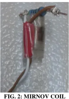
A hylam core is used for the coils. Coils are wound with different core dimensions (from 1 mm to 5 mm diameter) and different turns. Coil is terminated with a high termination resistance so that it can be used in voltage output mode.
FIG. 2: MIRNOV COIL III. MIRNOV COIL CALIBRATION Introduction
In order to calibrate Mirnov coil, it is necessary to generate a uniform magnetic field. This uniform magnetic field can be generated using a calibration system that may contain a pair of coils or a single coil. There are four different calibration systems to calibrate a magnetic sensor:
They are:
1) Single round loop 2) Round Helmholtz coil 3) Single square loop 4) Square Helmholtz coil
[image:2.595.47.291.460.563.2]All the four calibration systems are compared on the basis of the deviations of their axial magnetic fields. Each of the four calibration systems are single axis system, i.e., the calibration filed generated is parallel to only one of the three possible axes. The other two axes are not considered for calibration purposes. The following graph is the spherical test that finds the maximum, minimum and average z-directed magnetic induction on the surface of a sphere centered at the origin of each system. The radius of the sphere is varied from 0% to 96% of the radius of the round loops and from 0% to 96% of ½ the side length of the square loops [5]. The graph shown in figure 3 reveals that the round loop has the greatest deviation as a function of the sphere radius while the square Helmholtz has the least deviation as a function of the sphere radius.
[image:2.595.347.523.579.761.2]It can be concluded from figure 3 that the induced magnetic field of a Helmholtz coil system (round or square) is homogenous for 20% deviation from origin. Thus, the radius of the detector coil and length of its windings must not exceed 20% of radius of Helmholtz coil in case of round calibration system and 20% of ½ of the side length for a square system [5].
[image:3.595.298.554.150.312.2]A square Helmholtz coil system is constructed for calibration of Mirnov coils. The system is constructed of Perspex and wood using glue for construction. The side length of each coil is 10 cm and it has 5 turns of 0.67 mm enamelled copper wire. The two coils are connected in series and a Mirnov coil is placed at the centre of two coils for calibration, as shown in figure 4.
Fig. 4: Helmholtz coil to calibrate Mirnov coil Calibration of Helmholtz Coils
The magnetic field of Helmholtz coil is verified using a DSP based gauss meter of Lake Shore Cryotronics, with model no.:455. The meter uses hall probe as a sensor to sense magnetic fields. The probe is a transverse probe with model no.: HMNT-4E04-VR manufactured by Lake Shore Cryotronics.
The value of induced magnetic field density at the centre of coil system or at origin ((0, 0, 0) point) is given by following equation:
T
l
I
N
B
(
1
.
629
)
Where, ‘N’ is number of turns in each coil, ‘I’ is the current flowing in the coil system and ‘l’ is the side length of square Helmholtz system. The average percentage error between the theoretical value of flux density, as calculated from the equation, and that indicated by the gauss probe is found to be within ±5% of reading. This error is considered during Mirnov coil calibration and accordingly corrected.
Coil Calibration
Mirnov coil is placed in a square Helmholtz system, a discharge of current in the Helmholtz coils creates a change in the flux density, which is picked up by the Mirnov coil. The voltage produced by the Mirnov coil is acquired by the scope. This voltage is integrated using integration function of scope. The calibration factor of the coil is calculated by following equation:
B
Vdt
k
Experiments are carried out and the readings are taken at different values of discharged current and for each case the calibration constant ‘k’ is calculated. The final value of the calibration constant ‘k’ is obtained by taking average of all individual values of ‘k’ obtained for each discharge current.
Table 2: Mirnov coil calibration results Current
(A)
Coil Integration
(uVs)
Theoretic al B
(mT)
Calibrati on Factor
(mVs/m2)
4.73 0.4859 0.376 1.29
10.47 1.119 0.832 1.345
15.88 1.705 1.262 1.35
21.39 2.282 1.7 1.342
26.43 2.856 2.1 1.36
32.23 3.485 2.561 1.36
38.2 4.079 3.037 1.343
43.9 4.701 3.488 1.347
49 5.282 3.891 1.357
IV. EDDY CURRENTS EXPERIMENT & RESULTS Introduction
Eddy currents are currents induced in a conductor when it is exposed to changing magnetic field; due to relative motion of the field source and conductor or due to variations of the field with time. These circulating eddies of current can cause repulsive, attractive and drag effects. In tokamak, eddy currents are produced due to change in plasma positions during plasma instabilities. The presence of a high magnetic field due to toroidal field coils, induce electromagnetic forces on interaction with the induced currents. Mirnov coils are used to study plasma position during plasma disruptions. The coils are placed on different locations on the tokamak and by comparing the output of the coils, plasma positions can be identified.
Experimental Setup
Tokamak being a toroidal vessel, the experiment of eddy currents measurement is performed on a toroidal vessel. Instead of producing plasma, a coil with 16 turns is placed in the vessel [6]. The purpose of the coil is to increase the currents of the order of hundreds of amperes, which induces a large amount of eddy currents on the toroidal vessel.
[image:3.595.67.279.231.409.2]Fig. 5: Mirnov coils mounted on toroidal vessel
Results
[image:4.595.325.533.48.210.2]The coil at one location detects field generated due to currents flowing through that location. The flux density detected by the coil is proportional to current that induces it. The values of flux density for 3 locations as picked up by coils are given in table 3.
Table 3: Flux density picked up by Mirnov coils Position 1 Position 2 Position 3 Current
(A) B (mT)
Current
(A) B (mT)
Current
(A) B (mT) 16.8 11.14 213.2 67.55 18.3 38.37 37.6 25.99 236.2 78.22 37.7 99.03 55 38.87 255.6 85.18 55.7 152.44 75.4 53.4 271.1 90.44 76.2 215.18 93.7 67.03 285.6 94.96 93.3 270.37 By comparing the output of the coils, the current density profile on the vessel can be known. Simulation using FE ANSYS was carried out for the same experiment and the results were compared with the practical results. The current density distribution plot of toroidal vessel was obtained by simulation. From the results, it can be clearly observed that the current densities and hence currents are maximum in the inner section of the vessel. The currents are maximum in these volumes due to their proximity to the fields that are generated due to currents flowing through coil inside the toroidal vessel.
Fig. 6: Current density on vessel
[image:4.595.80.269.49.196.2]Also, from the simulation results of the magnetic density on vessel (as shown in fig.7), it is clearly observed that magnetic flux is density is higher at the inner section of
Fig. 7: Simulation result of magnetic flux density on vessel
Coil placed on inner side of toroidal vessel picked up more magnetic fields as compared to the coil that is placed on outer side of torus. Thus, the coils placed on the inner side fairly detect magnetic fields induced by eddy currents.
V. CONCLUSION
Rogowski coil and Mirnov coil are two important diagnostics used for eddy currents detection on tokamak. Rogowski coil detects average value of eddy currents flowing on tokamak. However, multiple Mirnov coils placed on tokamak gives information about eddy currents profile and thus plasma positions during plasma instabilities. Various important aspects related to the design and development of Mirnov coil is discussed in detail. With the help of the same, a more elaborative and practical construction of the coil is obtained. Helmholtz coil based test bench used to calibrate the Mirnov coil offers good accuracy to the Mirnov coil to be used for the eddy currents experiment. Results obtained through the Eddy currents experiment performed on a toroidal vessel are found in fair agreement with simulation and encouraging for the future work.
VI. ACKNOWLEDGMENT
The authors are grateful and indebted to Institute for Plasma Research. Special thanks to one and all, who have contributed directly or indirectly towards the project.
VII. REFERENCES
1. J. E. Lenz, “A review of magnetic sensors,” Proc. IEEE,
vol. 78, no. 6, Jun. 1990, pp. 973–989.
2. G. Dehmel, “Magnetic field sensors: Induction coil
(search coil) sensors”, Chapter 6 in Sensors – a
comprehensive survey, vol. 5, VCH Publishers, 1989, pp. 205-254.
3. R.F.K. Herzog, O. Tischler, “Measurement of
inhomogeneous magnetic fields”, Rev. Sc. Instr., vol. 24,
1953, pp. 1000-1001.
4. Slawomir Tumanski, “Induction Coil Sensors-A
Review”, J Measurement Science and technology, IOP
[image:4.595.81.264.577.723.2]5. William M. Frix, George G. Karady, Brian A. Venetz, “Comparison of Calibration Systems for Magnetic Field
Measurement Equipment” IEEE Trans. On Power
Delivery, vol. 9, no. 1, Jan. 1994, pp. 100–108.
6. N. Ravi Prakash, Kanikdeep Flora, Rajan Babu, R.
Gangradey, H. K. Patel, “Design and development of Rogowski Coil Sensors for Eddy Currents Measurement
on Torroidal Vessel,” Journal of Fusion Energy, vol. 32,