Abstract: In the recent years, many SMEs (small and medium enterprises) are taking a strategy to combine and sell their products and services to find new markets and reduce unnecessary expenses. For instance, in the case of the manufacturing facility manufacturers, they sell the manufacturing facility and additionally support the service which can monitor the status of that facility in real time. This strategic movement is a reflection of the purchaser’s requirements to reduce losses caused by an expected breakdown. In this paper, we introduce the pre-response maintenance systems to monitor the status of the heat transfer machine in real time and to carry maintenance out before the breakdown occurs.
Keywords: ALA; ALISE; ASIS&T; iSchools; LIS professional organisations; SLA; Social media outreach; Twitter analysis; Twitter use
I.INTRODUCTION
Recently, the Fourth Industrial Revolution is a hot topic. The Fourth Industrial Revolution means a technological revolution in which the boundaries of digital, physics, and biology are eliminated and all of them are merged following the third industrial revolution based on digital technology. Since the Fourth Industrial Revolution is expected to have a number of impacts on various fields, including economic and industrial structure and labor market, the existing manufacturing industry powerhouses are planning and implementing strategies to meet their industry changes in order to response quickly to these changes. In particular, these countries are paying attention to smart factory as future industry that will lead the Fourth Industrial Revolution [1, 2].
The smart factory is an intelligent factory which integrates product planning, design, production, distribution and sales using IT technologies and produces customized products at minimum cost and time. The powerhouses are trying to revitalize the stagnant manufacturing industry and enhance competitiveness through the dissemination of the smart factory [3-5].Despite these efforts, poor SMEs (small and medium enterprises), unlike big enterprises, are reluctant to adopt the smart factory while recognizing its advantages.
Revised Manuscript Received on May 22, 2019.
Jin-uk Jung, Department of Electronics Engineering, Changwon
National University, South Korea
Anugrah Moch Ilham, Department of Eco-Friendly Ocean Plant FEED
Engineering, Changwon National University, South Korea
Min-tae Hwang, Department of Information and Communication
Engineering, Changwon National University, South Korea
Kyo-hong Jin, Department of Electronics Engineering, Changwon
National University, South Korea
Because these companies are unable to afford the maintenance costs that arise after building the smart factory. The SMEs require a very simple smart factory or a system which is optimized for their business rather than a high-level smart factory supporting unnecessary functions [6, 7].
Meanwhile, a heat transfer machine is a kind of the printer that places a special film with a letter or a picture on the fabric and prints those by applying a low heat. The heat transfer machine is very sensitive to heat and the breakdowns associated to it occurs very frequently. The purchaser of this machine want to reduce unnecessary losses caused by unpredictable problems that may occur during their works. To solve this problem, we developed pre-response maintenance systems. Using the systems, the purchaser can minimize the losses by checking the condition of the machine in real time and performing the maintenance in advance before the breakdown occurs.
The rest of this paper is organized as follows. In Section 2 and 3, we introduce related works and heat transfer monitoring systems, respectively. Finally, conclusion follows in Section 3.
II.RELATED WORKS
Changwon is one of the largest industrial cities in Korea. In this city, there are many companies engaged in manufacturing industry. In fact, we had opportunities to meet with SMEs to hear about their difficulties and requirements with regard to building a smart factory. Not surprisingly, they want the establishment of the advanced smart factory based on artificial intelligence, machine learning, or big data, etc. However, they cannot afford to build such a high-level smart factory financially. Rather, they are interested in a very simple form of the smart factory that is optimized for their business or factory.
[8] introduces real-time free-length monitoring systems for the spring manufacturer. The spring manufacturer supplies their spring to the big automobile company. In recent years, the automobile company has required to upload an Excel file that contains information about all springs to its own quality management systems. Therefore, this spring manufacturer wants to build systems which can check whether the produced spring is defective or not and show how many the spring has been produced. The developed systems consists of an IoT (Internet of Things) device, a server system including a server program and a database, and a user program.
Development of Pre-response Maintenance
Systems for Stable Operations of Heat Transfer
Machine
There is a spring free-length sorter which is connected to the IoT device and a spring manufacturing equipment.
The role of this sorter is to detect a free-length of a coil-type spring by using non-contact sensor and determines whether the produced spring is normal or abnormal. The data for all springs are transmitted to the server program on the server system by the IoT device and stored into the database. The information in the database will be utilized by the user program. The purpose of this systems is to monitor the quality of the spring and does not include the function for the maintenance of the manufacturing facility.
SMEs which make the manufacturing facility wants to minimize useless costs for the maintenance. Also, the manufacturers want to know the status of the facility and control in remote area. To resolve the problem like this, [9] introduces real-time monitoring and remote control systems for an ice machine. This systems consists of IoT device connected to a control panel on the ice machine, a server systems for storing the information from IoT device, and a web-based user program and a mobile device application for monitoring the status of the ice machine or controlling the ice machine in a remote area. This systems provide the function to send an alarm message to a worker when a failure occurs. With this function, the worker who receives the alarm message can quickly respond to the failure. However, many companies who have the facilities to be operated for a long time want to avoid the halt of the production caused by the unexpected failure. In other words,
they require B/S (Before Service). However, this system supports only A/S (After Service).
The systems proposed in this paper support both A/S and B/S. Before occurring the failure, if the maintenance is performed in advance, the companies will be able to reduce unnecessary expenses due to the unexpected failure.
III. PRE-RESPONSE MAINTENANCE SYSTEMS
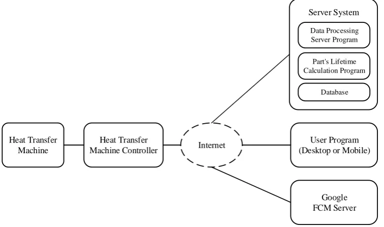
Figure 1 shows the block diagram of the developed systems. This systems consists of a heat transfer machine, a heat transfer controller machine, a server system, and a user program. The developed systems operates as follows. First, the heat transfer machine controller collects and analyzes data detected by sensors installed in the heat transfer machine. Then, the heat transfer machine status information message including the sensor data, the result data of analyzing the sensor data, and the state data of the heat transfer machine are generated and transmitted to the data processing server program. The data processing server program checks the status data of the heat transfer machine in the received message. If there is a problem with the heat transfer machine, it sends an alarm message to the user program using Google FCM (Firebase Cloud Messaging) [10]. It then stores all the data in the message into the database. The data stored in the database is utilized by the user program. A user can see the data of the heat transfer machine and receive the alarm message through the program.
Heat Transfer Machine
Heat Transfer Machine Controller
Server System
User Program (Desktop or Mobile) Internet
Part's Lifetime Calculation Program
Database Data Processing Server Program
[image:2.595.111.489.403.626.2]Google FCM Server
Fig. 1 The block diagram of the developed systems
Heat Transfer Machine
Fig. 2 The small-sized heat transfer machine for the test Heat Transfer Machine Controller
Basically, there is a controller for controlling the heat transfer machine. However, this controller does not include a communication function to transmit data to a remote server. Therefore, we developed the IoT device that can be connected to the existing controller to support the communication function. Figure 3 shows the controller and the IoT device connected it.
[image:3.595.50.289.55.217.2]. Fig. 3 The existing controller and IoT device
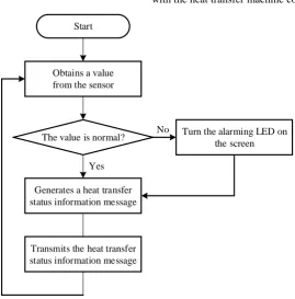
The role of the heat transfer machine controller is threefold. The first role is to collect the data detected by the temperature sensor attached to the heat transfer machine’s drum. The second role is to analyze the collected data and display them on the screen of the controller according to the result. Finally, the controller configures the collected sensor data, the result data obtained by analyzing the data, and the various data related to the heat transfer machine as a heat transfer machine status information message. And transmits the message to the data processing server program operating on the server. Figure 4 shows the flowchart of the operation with the heat transfer machine controller.
Start
Obtains a value from the sensor
The value is normal?
Generates a heat transfer status information message
Turn the alarming LED on the screen
Yes
No
Transmits the heat transfer status information message
Fig. 4 The flowchart of the operation with the heat transfer machine Server System
[image:3.595.166.436.391.665.2]Server System
Database Part's Lifetime Calculation Program Data Processing
Server Program
Google FCM Server Heat Transfer Machine
Controller
Alarm Message for the machine's condition
Alarm Message for the part's lifetime Data from the Heat
Transfer Controller
Data for Part's Lifetime Calculation
[image:4.595.145.448.53.226.2]User Program
Fig. 5 The block diagram of the server system The data processing server program receives the heat
transfer machine status message from the heat transfer controller and stores the significant data included in the message into the database.
The stored data is utilized for two purposes. The first purpose is for monitoring in the user program. The purchaser can monitor the status of the current condition of the heat transfer machine through the user program in real time. The user program displays the data as a line graph. Another purpose is to calculate the lifetime of a part. This calculation is made in the part’s lifetime calculation
program. The calculated results are delivered to the data processing server program. Using the result, the program configures an alarm message forwards it to the Google FCM server.
Data Processing Server Program
This program processes the heat transfer machine status message from the heat transfer machine controller. Based on the data contained in this message, this program can know the current status of the heat transfer machine.
Start
Receives a heat transfer machine status message
Analyzes the message
Abnormal Condition? Transmits the alarm message to FCM Server
Stores core data into the database
Yes
[image:4.595.160.449.403.662.2]No
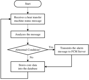
Fig. 6 The block diagram of the server system Figure 6 represents the flowchart of this program. This
program is always in operation to receive the message from the heat transfer machine controller. When a message is received from the controller, it analyzes the message to check the condition of the machine. If there is a problem with the machine, the program generates an alarm message and sends it to the FCM server. Then, FCM server will deliver this message to the user program of the purchaser
Part’s Lifetime Calculation Program
As mentioned before, the purchaser of the heat transfer machine wants to reduce losses caused by the suspension of the work. The goal of this program is not to determine whether a breakdown is occurred or not, but rather to minimize the suspension by performing the maintenance before the breakdown.
Meanwhile, all parts in the heat transfer machine have own lifetime. The recommended lifetime of each part is stored in the database. This program calculates the remaining lifetime of the parts based on the operating time. That is, the remaining of the part is the recommended lifetime minus the total operating time of the heat transfer machine.
When the end of the part’s lifetime is near, the program sends the alarm message to user program. This also uses FCM.
Database Design
To store the information related to the operation of the developed systems, we designed two databases named Information_DB, Data_DB.
In Information_DB, there are six tables as shown in Table 1. Machine_info table contains a list of all the heat transfer machine sold by the manufacturer. This table is required to display the list of the machine owned by the purchaser through the user application. In Part_lifetime table, the recommended lifetime of the major parts constituting the
machine is stored. The values in this table are used when the part’s lifetime calculation program calculates the remaining lifetime of the parts. If there is a problem with the machine, a service staff of the manufacturer will repair it. When the repair is complete, the staff must record the repair details. The details are stored in Maintenance_history table. The token is obtained from the FCM server when the user logs in the user program. The user program stores this token in the Token_list table. The stored token is used to send an alarm message to the user program via the FCM server. The user program is a web-based application. Therefore, if the purchaser wants to check the status of the heat transfer machine in real time through the user program, it must subscribe to the web site operated by the manufacturer. The information stored in the User_info table are the user information recorded when the user subscribes to the web site to utilize the user program.
There is only one kind of the table in Data_DB. The name of this table is the combination of today’s date and the serial number in the heat transfer status information message received from the heat transfer machine controller. This table is automatically generated by the data processing server program. When the data processing server program receives the message from the controller, it first checks to see if a table with the same name as the combination is in the database. If the table exists, it stores the data in the table. Otherwise, after creating the table, it stores the data in the table.
Table. 1 The five tables in Information_DB
Table Name Description
Machine_info The general information of each machine are stored.
Part_lifetime The major parts’ lifetime of the heat transfer machine are stored in this table.
Maintenance_history This table is used for recording the breakdown and the repair details of the heat transfer machine.
Token_list It is the table in which a token required for transmission of an alarm message is stored using FCM.
User_info The information of the subscriber using the heat transfer machine monitoring web service are stored in this table.
User Program
The two major services of the user program are to show the data of the heat transfer machine stored in the database on the screen and to indicate a machine’s breakdown or a part’s replacement time using the alarm message.
For the implementation of these two services, we adopted RWD (Responsive Websites Design) and WPN (Web Push Notification).The reason why we chosen RWD is because it offers the advantage of automatically adjusting the layout according to the size of the web browser running on the device that accesses the web page. If without using RWD, it is necessary to develop a separate application for mobile devices.
There are two kinds of push notification, MPN (Mobile Push Notification) and WPN. MPN is for the applications of the mobile device called as app. In developing an application for the mobile device, the biggest problem is that the application has to be developed using the different programming languages depending on platforms, such as
Android, iOS, Windows. However, this problem can be easily solved by using WPN. Since WPN is used with a web
browser, if the browser is supported, only one web-based application needs to be developed, regardless of the platform.
Monitoring the machine’s condition
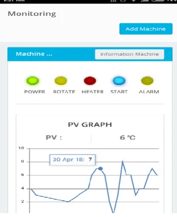
The user can leverage the web application on the desktop and the mobile device. Figure 7 and 8 are the screenshot for the monitoring page of the web application on the desktop and on the mobile device, respectively. The user can check the current status of the heat transfer machine through five icons on the upper part of the screen, and monitor the temperature data displayed in the below broken line graphs in real time. Figure 8 shows the layout altered to fit the smaller screen of the mobile device by applying RWD to the layout in Figure 7. The web application running on the desktop and on the mobile device only differ in the overall layout, but all functions are
Fig. 7 The screenshot for the monitoring page of the web application on the desktop
Fig. 8 The screenshot for the monitoring page of the web application on the mobile device Displaying the Alarm Message
The alarm message transmitted from the data processing server program is delivered to the user program via the FCM server. Figure 9 and 10 are the screenshots successfully receiving an alarm message on the desktop and the smart phone, respectively.
The received message contains the information that the lifetime of the motor is 500 hours. The field-worker or the process manager can use this information to check the condition of the motor and perform the maintenance before the breakdown occurs.
[image:6.595.138.463.588.724.2]Fig. 10 The screenshot for receiving the alarm message on the smart phone
IV. CONCLUSION AND FUTURE RESEARCH
In this paper, we introduced the pre-response maintenance systems to replace and repair the parts of the heat transfer in advance in order to prevent the suspension of the production due to the breakdown. Through this systems, the heat transfer manufacturers can reduce the cost caused by unnecessary maintenance service after sale. The heat transfer purchasers can increase the production efficiency and minimize losses due to the suspension.
In the future, we will develop and add predictive diagnostic algorithm that can predict the breakdown in the manufacturing facility
Declaration of conflicting interests
The author(s) declared no potential conflicts of interest with respect to the research, authorship and/or publication of this article.
ACKNOWLEDGEMENTS
This work was supported by the Technological Innovation R&D Program(S2449090) funded by the Small and Medium Business Administration(SMBA, Korea).
This research was supported by the MIST(Ministry of Science and ICT), Korea, under the Grand Information Technology ResearchCenter support program(IITP-2018-2016-0-00318) supervised by the IITP(Institute for Information & communications Technology Promotion).
REFERENCES
1. You YS. China’s ICT industry and policy trend to prepare for the Fourth Industrial Revolution,
http://alio.go.kr/download.dn?fileNo=2270618 (2017, accessed July 2018).
2. Kim CY. Smart Factory: the industry to grow with the Fourth Industrial Revolution, http://file.mk.co.kr/imss/write/201710191 03317__00.pdf (2017, accessed July 2018).
3. Ministry of Trade, Industry and Energy. A study on the future direction of smart factory and the development plan of smart manufacturing industry.
http://www.prism.go.kr/homepage/entire/retrieveEntireDetail.do;jsessi onid=BB32051CC76975D7C60442656A5E8C16.node02?cond_resear ch_name=&cond_research_start_date=&cond_research_end_date=&re search_id=1450000-201600115&pageIndex=38&leftMenuLevel=160 (2016, accessed July 2018).
4. Go JJ and Lee KT. Smart factory’s current status and implications, http://www.fkii.org/2014/board/tot.read.php?SC_field=&SC_word=& BBS_GUBUN=6&page=1&BBS_IDX=12091 (2015, accessed July 2018).
5. Jeon EK. Current status and improvement issue of smart factory’s policies. http://www.nars.go.kr/brdView.do?cmsCd=CM01 55&brd_Seq=21687 (2017, accessed July 2018).
6. Hong SM. A study on the establishment of smart factory for small and medium-sized enterprise. http://procon.co.kr/pdf/2017%208/1-1.pdf (2017, accessed July 2018).
7. Lee HJ, Kim YJ, Lim JI, and Kim YW. Analysis of field conditions and requirements for deploying smart factory. Journal of the Korean Society for Precision Engineering 2017;34(1): 29-34.
8. Jung JU, Kim SH, Jin KH. The development of real-time free length monitoring systemsinterlocking with PLC device. In: Proceeding of the 2016 Spring Conference of Korea Institute of Information and Communication Engineering. Busan:Korea Institute of Information and Communication Engineering. 2016, pp.539-541.
9. Kim SH, Jung JM, Jung JU, Hwang MT, and Jin KH. Development of the ice machine condition monitoring system for remote diagnosis. In: Proceeding of the 2016 Fall Conference of Korea Institute of Information and Communication Engineering. Daejeon: Korea Institute of Information and Communication Engineering. 2016, pp.230-233. 10. Firebase Cloud Messaging.