International Journal of Innovative Technology and Exploring Engineering (IJITEE) ISSN: 2278-3075, Volume-8, Issue-7S, May 2019
Abstract: Numerical simulation has been carried out to study the gaseous jet interaction with cross flowing airstream using toluene and air as working fluids. Species transport model is used in the present analysis, which is capable of predicting the interface between these two different fluids each of which is having different mass densities. Both steady and transient conditions have been simulated to study these interactions between toluene gas and cross flow air and results were compared. Aerodynamic effect of turbulent round gaseous jet is captured at different downstream locations and compared in steady analysis. Snapshots have been captured to portray the temporal evolution of the gaseous jet forming the spray at different time step in transient analysis. Effect of maximum penetration of gaseous jet in response to high speed subsonic cross flow have been studied in transient analysis. The knowledge acquired from these results which leads to understand the annulus jet interaction into cross flow airstream in gas turbine combustors. Deformation of turbulent round gaseous jet is captured at different downstream locations and compared in steady analysis. The temporal evolution of the gaseous jet forming the spray is captured at different time step and compared in transient analysis. Following observations have been made from the present simulations; Increase in time step locally increases the maximum penetration of gaseous jet and gradually decrease for successive time steps and finally the gaseous jet become stable in response to high speed subsonic cross flow. Deformation of round gaseous jet into inverted heart shape structure is due to counter rotated flow in response to aerodynamic effect of cross flow airstream.
Keywords: Jet in Cross flow, Species transport model, Steady and Transient analysis.
I. INTRODUCTION
Figure 1, shows the schematic diagram of a turbulent round jet flowing from the upper annulus reservoir into the liner region. However, the liner fluid is also in motion flowing from left to right with a velocity. The cross flow airstream sees the vertical jet as a cylindrical obstruction in the flow, and so it exerts aerodynamic drag force upon it.
Revised Manuscript Received on May 05, 2019.
D.Muruganandam, Professor, Department of Mechanical Engineering, Jeppiaar Institute of Technology, Chennai.
J.Jayapriya, Assistant Professor, Department of Mathematics, Sathyabama Institute of Science and Technology, Chennai.
M.K.Karthik, Assistant Professor, Department of Mechanical Engineering, Jeppiaar Institute of Technology,Chennai.
S.Suraj, Assistant Professor, Department of Mechanical Engineering, Jeppiaar Institute of Technology, Chennai.
The jet being a complaint structure instead of a rigid cylinder. It deforms in response to the drag force and it is bent down horizontally and diluted in downstream.
In addition to this jet entrainment as a result of the sequence of ring vortices, primary mixing takes place and the region of primary mixing is surrounded by potential core which is shown in the second image of Figure 1. There is now an additional set of horse shoe vortices as depicted in the figure due to the vertical vortex filaments established in the wake of the jet. This creates second mixing system extending in the cross-stream air flow direction[1].
An expression for the trajectory of the jet centerline is given by Lefebvre [2]
As the jet mixes out into the flowing stream, jet centerline must eventually become parallel to the velocity . However, an one-third power exponent in the above equation does not approaches an asymptote for y as x increases. So, equation only describes the jet trajectory only in the near field.Lefebvre gives an empirical equation for the asymptote, namely, the maximum jet penetration depth.[2]
[image:1.595.325.528.423.621.2]
Fig . 1 Gaseous jet in cross flow[1]
Elshamy et al [3] studied the structure of liquid jets injected transversely into high-speed subsonic cross flows at elevated ambient pressure experimentally. As the momentum flux ratio is increased, the transverse distance as well as the droplet velocity of the spray core is increased, while the droplet velocity at the outer periphery is decreased. The droplet velocity peaked at the outer periphery for the column breakup location. Oppositely, it peaked at the inner periphery for the surface breakup.
Computational Analysis of Gaseous Jet in a
Cross Flow
At higher ambient pressure, the penetration of the jet slightly decreased and the spray coverage area decreased. Xiao. F et al [4] developed a two-phase- flow LES methodology to analyze the primary-breakup mechanism of liquid jet in an air cross flow.
Based on the simulation results they demonstrated that the surface wavelength of upstream side of liquid column decreases with Weber number. For a turbulent liquid jet, the spray structure and liquid jet penetration in an air cross flow were well produced by simulations. Larger liquid to density ratio of liquid jet in cross flow air does not allow turbulence of gaseous flow to affect the liquid interface. Marzbali et al [5] carried out theoretical analysis of liquid jets in a subsonic gaseous cross flow. They observed that at elevated pressure and temperature, mass stripping from the jet surface becomes more important as the free stream gas density is increased at higher temperatures and pressures. Mohit et al [7] developed a multiphase model and study the deformation of circular liquid jet in cross flow. Also, they observed the aerodynamic effect on circular jet in a cross flow.
II. CFD METHODOLOGY
[image:2.595.308.555.78.288.2]The computation domain used in the CFD analysis is shown in the figure 2. A Species transport model is used in the present computational analysis, which is capable of predicting the interface between toluene and air phases. Initially a grid independent study has been carried out, by simulating a liquid jet in cross flow in the computational domain with four different grid sizes. Performance parameters like mid plane species contour, mass fraction of toluene gas profile and velocity profile at different downstream locations has been compared for different cases. And one particular grid size is chosen with reasonable computational cost for the rest of analysis. Pressure inlet and pressure outlet boundary conditions have been chosen at inlet and outlet of computational domain respectively. In the computational analysis, the jet interaction is analyzed in confined conditions. Initially larger computational domain is considered for the interaction of gaseous jet in cross flow study. Later, by observing the Species contour at mid plane and top plane; width, height and length of the computation domain have been reduced and dimensions of computational domain have been optimized.
Fig. 2 Computational domain used in CFD analysis
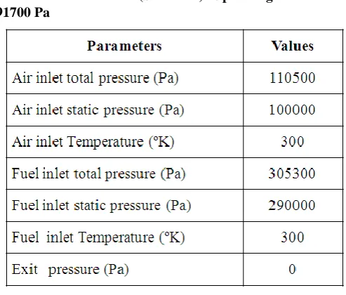
III. BOUNDARY CONDITIONS
Table 1 . K- Model (Standard) Operating Pressure: 91700 Pa
IV. RESULTS AND DISCUSSION Steady flow CFD Results
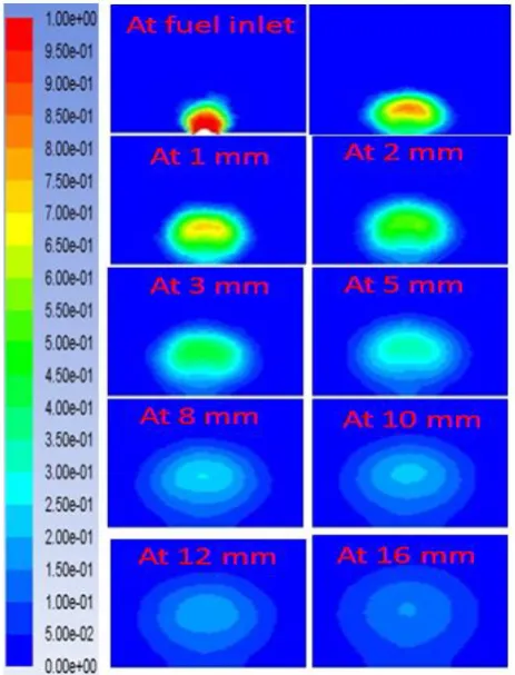
Figure 3shows the top plane species contour at different heights.Initially at 0.1 mm height, gaseous jet penetrate with high species concentration gradient near the fuel inlet. Further downstream it forms strong potential core at the centre of jet which is surrounded by partially mixing region. Here downstream in the sense transverse direction of cross flow air stream.
[image:2.595.49.295.593.769.2]International Journal of Innovative Technology and Exploring Engineering (IJITEE) ISSN: 2278-3075, Volume-8, Issue-7S, May 2019
Further downstream locations, the gaseous jet penetrate inside the chamber in transverse direction and settled down at one stage.Then,the jet is carried away by the cross flow airstream due to shear interaction between the gaseous jet and air.In this top plane species contour analysis at different transverse locations, it is observed that width of the gaseous jet is continously increasing due to mixing effect of toluene gas with cross flow air. Also, it is noted that the gaseous jet penetrates till 2.5 mm. After, that it is not penetrating further because of lower concentration of density gradient.
[image:3.595.312.544.254.558.2]Figure 4shows the species concentration profile at different downstream axial locations.It can be clearly understood that, at fuel inlet species concentration of toluene gas is very high and reached mass fraction of C7H8 as 1. Downstream of fuel inlet there is continuous reduction in the species concentration. This is due to the mixing effect of toluene gas (C7H8) with cross flowing airstream which will diluted the species concentration in downstream. Also, it can be clearly seen that from the variation in the species concentration profile, there is a continuous reduction in the maximum (peak) value of mass fraction of (C7H8). From this it is understood that the mixing of toluene gas and air takes place along the axial direction of the gaseous spray and reduce the core species concentation. And,also it is observed that, near the orifice the width of the gaseous jet become less. This is because the toluene gas is having high species concentration and also complete mixing of toluene and air not takes place. At downstream locations, there is a reduction in species concentration gradient due to mixing phenomenon.Hence, the width of the gaseous jet is continuously increased along the axial direction of the gaseous spray. This is due to species interaction of gaseous jet with cross flowing airstream in the downstream of the spray.
Fig. 4 Species concentration profile at different downstream axial locations
Figure 5shows the transverse plane species contour at different axial locations from fuel inlet to 17mm downstream of fuel inlet.Here downstream in the sense cross flowing airstream direction. It is observed that from the mid plane species contour from Figure 5,gaseous jet is flowing from the fuel pipe by forming strong otential core in the middle and it is moving along flow direction inside the chamber. At fuel inlet, mass fraction of toluene gas (C7H8)
is having very high concentration in the middle(say 1).This is observed as red colour in the first image of Figure 5. Due to the interaction between air and gaseous jet the concentration of species get reduced which is observed as green colour in the first image of Figure 5.Further downstream axial locations species concentration of toluene gas (C7H8) get reduced. This means that toluene gas molecules get interacted with incoming cross flowing airstream and diffusion in the molecules has been takes place in the downstream locations. Also, it is observed that there is a deformation of cylindrical structure of gaseous jet in downstream location. This is because of vortices created by the cross flow air stream at the bottom portion of the gaseous jet. This vortices created due to flow reversal which is going to take care about mixing phenomenon in downstream locations.
Fig. 5 Transverse plane Species contour at different downstream axial locations
Aerodynamic effect of cross flow airstream on structure of gaseous jet
[image:3.595.43.293.468.640.2]The strong reverse flow of air stream has been clearly captured by computational analysis. This strong reverse flow is responsible for deformation of the gaseous jet and contributes to enhance the recirculation zone.
[image:4.595.311.551.55.416.2] [image:4.595.49.292.248.484.2]The species contour of gaseous jet at different transverse location with velocity vector is shown in first image of figure 6; clearly depicts the deformation of gaseous jet along transverse direction. The cross section of gaseous jet near orifice is almost circular but away from the orifice, the cross section of jet column completely changes. To understand the effect of cross flow airstream, the structure gaseous jet at different transverse location has been captured and compared in first image of figure 6. It clearly shows that the deformation in the structure of gaseous jet is strongly depend on the reverse flow created in the cross flow air stream.
Fig. 6 Deforming structure of gaseous jet along transverse direction
Unsteady flow CFD Results
Figure 7 shows temporal evolution of mid plane species contour of toluene gas with cross flow air.It represents that toluene gas (C7H8) enters gradually inside the mixing
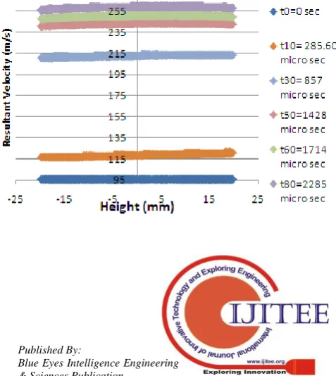
chamber from the fuel pipe. At initial time step, the contribution of cross flow air inlet velocity is very less which is observed in the Figure 8 at time step t0. Hence, the
gaseous jet is locally penetrates higher at initial time steps till t10 which is also observed in the midplane species
contour at same time step. After this time step, the cross flow air inlet velocity is gradually increased and settled down. So, it does not allow the toluene gas to penetrate further higher inside the mixing chamber.This bends the gaseous jet horizontally in the cross flow airstream direction. This is due to the aerodynamic effect of cross flow airstream upon the jet.
Fig. 7 Temporal evolution of midplane species contour This is observed in Figure 7 at t = 857 micro sec.Finally from time step t60, the gaseous jet is settled down which is observed in Figure 7 and also,from the inlet velocity profile in Figure 8 at time step t60 .
[image:4.595.310.549.559.826.2]International Journal of Innovative Technology and Exploring Engineering (IJITEE) ISSN: 2278-3075, Volume-8, Issue-7S, May 2019
Fig. 8 Temporal evolution of resultant velocity at air inlet.
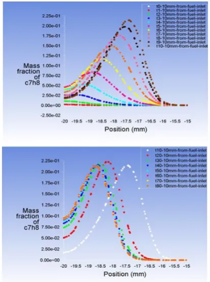
Also, it has been observed from the figure from initial time step to tenth timestep mass fraction of toluene gas (C7H8) is continuously increasing and also the species concentration profile moving towards top portion of the chamber which is observed from the Figure9. After that,the species concentration profile is gradually moves towards bottom portion of the mixing chamber and the mass fraction of toluene gas (C7H8) almost remains same for some final time steps. This is due to the effect of cross flow inlet velocity which means very less velocity is produced at initial time steps.Hence, the gaseous jet penetrates higher till tenth time step which give reason to the shifting of species concentration profile towards top side of the mixing chamber. After tenth time step, cross flow inlet velocity is increased.
Fig. 9 Temporal variation of species concentration profile.
And ,this is going to dominate the gaseous jet which in turn affects jet penetration.So, the species concentration profile shifting towards bottom portion of the mixing chamber after tenth time step and remains same for some final time steps.
[image:5.595.51.258.457.734.2]Temporal variation on the structure of the gaseous jet
Fig. 10 Temporal variation of transverse plane species contour at different axial locations.
Figure 10 shows temporal variation of mass fraction of toluene gas (C7H8) at different transverse planes and at
different downstream axial locations.This shows that, gaseous jet enters gradually into the mixing chamber and mix with cross flow airstream at downstream. It also shows that locally there is a change in the shape and structure of the gaseous jet. This is due to the effect of cross flow airstream in the mixing chamber. The cross flow air stream sees the vertical jet as a cylindrical obstruction in the flow. Hence it exerts aerodynamic drag force upon it. The gaseous jet become a pliable structure instead of a rigid cylinder. It deforms in response to the aerodynamic force and it is diluted in the downstream.In addition to jet entrainment as a result of the sequence of ring vortices, which is also having counter rotated flow established in the wake of the jet. The same has been observed in steady results from Figure 5. That’s why the gaseous jet deforms into inverted heart shaped structure in the downstream axial location which is shown in the Figure 10 at 1.5 mm downstream of fuel inlet. This creates second mixing system extending in the cross flow airstream direction.
90 110 130 150 170 190 210 230 250 270
0 1000 2000
R
es
ul
tan
t
V
el
oci
ty
a
t
ai
r
in
le
t
(m/
s)
Time variation of the resultant velocity profile at exit
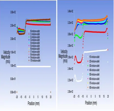
Fig. 11 Time variation of Resultant velocity profile at exit
Figure 11 shows the temporal evolution of resultant velocity profile at exit.This shows that, at initial time step flat resultant velocity profile is exist at exit. This is because the toluene gas is fully mixed with air and get diluted near the fuel pipe.Later the toluene gas enters more and it is not completely mixed with incoming airstream. Hence, the resultant velocity at exit get disturbed near the bottom portion of the chamber which is observed from the Figure 11. Finally the mixing phenomenon increases due to increase in inlet cross flow velocity.Hence it shows almost flat velocity profile.
V. CONCLUSION
Computational analysis has been simulated to study the gaseous jet interaction with cross flowing airstream using toluene and air as working fluids. Species transport model is used in the present analysis, which is capable of predicting the interface between these two different fluids each of which is having different mass densities. Both steady and transient conditions have been simulated to study these interactions between toluene gas and cross flow air and results were compared.
The main results of the computational study can be summarizes as follows:
Deformation of round gaseous jet into inverted heart shape structure is due to counter rotated flow in response to aerodynamic effect of cross flow airstream.
Increase in time step increase the maximum penetration of gaseous jet initially and decreases gradually for successive time steps and finally the gaseous jet become stable in response to high speed subsonic cross flow.
VI. ACKNOWLEDGEMENT
The authors are thankful to personal guide for permitting to publish this work. The authors are thankful to all the teachers for their encouragement to this work.
VII. NOMENCLATURE t – Time step
UL – Liner velocity
Vj – Cross flow gaseous jet velocity
x – Air stream direction
y – Distance along transverse direction d – Diameter of orifice
q – Momentum flux ratio We – Weber number
REFERENCE
1. Aircraft engine design by Jack D Mattingly
2. Arthur H Lefebvre and Dilip R. Ballal, “Gas Turbine Combustion Alternative Fuels and Emissions”, Third Edition, CRC Press, Tylor and Francis Pub, 2010.
3. Elshamy O.M, TambeS, CaiJ, and JengS- M,”Structure of Liquid Jets in Subsonic Crossflow atElevated Ambient Pressures”, University of Cincinnati, Cincinnati, OH, AIAA 2006-1224
4. F.Xiao, M.Dianat and J.J. McGuirk, “ Large eddy simulation of liquid-jet primary breakup in air cross flow” AIAA Journal, Vol 51. No 12, December 2013
5. MarzbaliS.N and DolatabadiA, “Near-field Trajectory of Circular Liquid Jets Injected into Subsonic Gaseous Crossflow”, Concordia University, Montreal, Quebec, Canada, H3G 1M8 AIAA 2011-186 6. Jacob N. Stenzler, Jong G. Lee, and Domenic A.
Santavicca,“Penetration of Liquid Jets in a Crossflow,Department of Mechanical and Nuclear Engineering, The Pennsylvania State University, University Park, Pennsylvania 16802,AIAA 2003-1327 7. Mohit jain, Gaurav tomar, RV Ravikrishna, Surya prakash R,
![Fig . 1 Gaseous jet in cross flow[1]](https://thumb-us.123doks.com/thumbv2/123dok_us/8203325.261501/1.595.325.528.423.621/fig-gaseous-jet-cross-flow.webp)