A PRELIMINARY STUDY OF CONTROL PARAMETERS FOR OPEN FURNACE MILD COMBUSTION USING CFD
M. M. Noor1,3*, Andrew P. Wandel1 and T. F. Yusaf2,3
1
Computational Engineering and Science Research Centre, Department of Mechanical and Mechatronic Engineering,
University of Southern Queensland (USQ), Australia
2
National Centre for Engineering in Agriculture, University of Southern Queensland (USQ), Australia
3
Faculty of Mechanical Engineering, Universiti Malaysia Pahang (UMP), Malaysia
*
Corresponding Email: [email protected]
ABSTRACT
Pollution regulation and demand for efficient energy have driven the combustion community to work on combustion improvement. Moderate or Intense Low oxygen Dilution (MILD) combustion is one of the best alternative new technologies for clean and efficient combustion. MILD is proven to be a promising combustion technology for industrial applications. This paper studies the design stage for an open furnace with exhaust gas recirculation (EGR) captured from the flue gas. This study uses ANSYS Fluent to simulate and predict the parameters. The study started with 3D furnace with two EGR. Due to incorrect flow, modifications have been made to the EGR inlet and outlet. Finally 3D model with four EGR was developed and was successful in producing the desired flow in the EGR.
Keywords: MILD combustion, computational fluid dynamics, exhaust gas recirculation,
turbulent, open furnace
INTRODUCTION
47
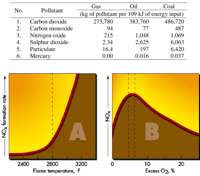
Among fossil fuel, natural gas combustion is the most attractive since it produces less harm to the environment because it releases less carbon dioxide, nitrogen oxide, sulphur dioxide, particulate and mercury per unit energy compared to oil and coal (EIA, 1999). In 2009, the estimated natural gas reserves is 187.5 trillion cubic meters, which can supply up to 7x10¹⁵ MJ of energy, and the petroleum reserves can supply up to 1383 billion barrel which can supply 8.4x10¹⁵ MJ of energy [BP, 2010, 2011]. Table 1 show the comparison of pollutants for natural gas, oil and coal. The use of natural gas will reduce the impact of fossil fuel combustion on climate change. In order to reduce further on NOx and other harmful pollutant, lean mixture will reduce the combustion
temperature and reduce the formation of NOx. Beside fuel NOx and prompt NOx, the
thermal NOx is the main NOx formation will increase rapidly after the combustion
temperature reach 1573 K (EPA, 1999) and 1810 K (AET, 2012). Figure 1 shows the formation of NOx. In order to achieve the low NOx emission and high thermal efficiency
[image:2.595.100.501.359.712.2]combustion, MILD combustion technology is the proper selection which will give low NOx emission and high thermal efficiency combustion.
Table 1. Pollutant from fossil fuel (EIA, 1999)
No. Pollutant Gas Oil Coal
(kg of pollutant per 109 kJ of energy input)
1. Carbon dioxide 273,780 383,760 486,720
2. Carbon monoxide 94 77 487
3. Nitrogen oxide 215 1,048 1,069
4. Sulphur dioxide 2.34 2,625 6,063
5. Particulate 16.4 197 6,420
6. Mercury 0.00 0.016 0.037
Figure 1. The rate of NOx formation, (a) flame temperature in Fahrenheit (2800 F is
48
[image:3.595.137.459.327.567.2]MILD combustion technology comes from the concept of excess enthalpy combustion (Hardestry and Weinberg, 1974). This combustion is also called flameless oxidation or FLOX (Wünning, 1991, 1996, Wünning and Wünning, 1997 and Milani and Wünning, 2007), low NOx injection (Orsino et al., 2001), Moderate or Intense Low-oxygen Dilution (MILD) combustion (Dally et al., 2002, Cavaliere and de Joannon, 2004, Christo and Dally, 2004) and high-temperature air combustion (HiTAC) (Katsuki and Hasegawa, 1998 and Tsuji et al., 2003). MILD combustion technology utilizes the heat and exhaust gas recirculation (EGR) or flue gas recirculation (FGR) to achieve stable low temperature combustion under a hot oxidant diluted condition. MILD combustion has been achieved experimentally (Dally et al., 2008, Li and Mi, 2010, Mi et al., 2010 and Li et al., 2010a, 2010b) and numerically (Scharler R and Obernberger, 2000, Giammartini et al., 2000, Awosope et al., 2006, Galletti et al., 2007, 2008, 2009, Mollica et al., 2009 and Szegö et al., 2003, 2009, 2010) in premixed and non-premixed combustion modes.
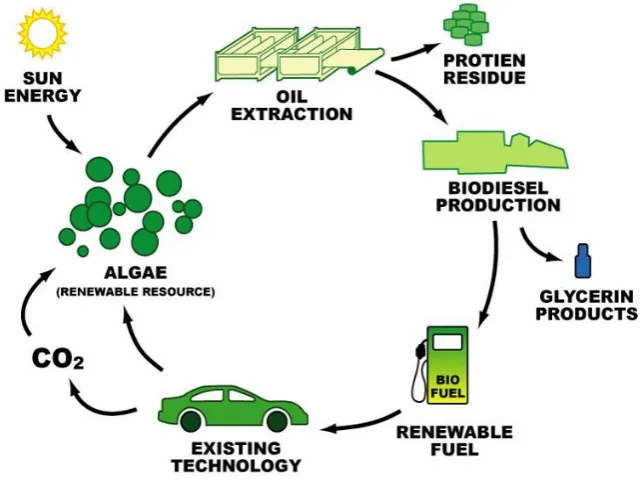
Figure 2. Carbon dioxide close cycle for biofuels (www.knol.google.com)
Beside NOx emission and efficiency issue, another important issue in
combustion is CO2 emission which will also impact on greenhouse gasses (GHG)
(Volk, 2008). Energy Information Administration (EIA, 2002, 2007 and 2011) reported that CO2 emissions from combustion account for about 80% of anthropogenic GHG. In
order to reduce CO2 emissions, biogas will be the best alternative since biogas produced
from biomass uses CO2 in the photosynthesis stage; hence this will reduce the CO2 in
49
biofuels are derived from soy beans while in Europe rapeseed is the largest source. Biogas normally consist of about 50% methane with the heating value of 21MJ/Nm3, the density is 1.22 kg/m3, which is similar to air: 1.29 kg/m3 (Al-Seadi et al. 2008). Biogas also suitable for the internal combustion engine (ICE) used. Huang and Crookes (1998) and Borjesson and Mattiasson (2008) studied the efficiency of biogas for ICE, Caresana et al. (2011) used it for energy production, Colorado et al (2010) and Effuggi et al. (2008) use for MILD furnace combustion. The computational work was carried out using Fluent 13.0 (ANSYS 2010) in a preliminary study of the control parameters for open furnace combustion. The parameters involved are air and fuel velocity injected, nozzle design, chamber design, EGR design and exhaust design. The purpose of the study is to analyse and optimise the parameters and predict the flame behaviour.
GOVERNING EQUATIONS
Fluid flow governing equations consists of continuity equation, density, enthalpy, temperature, species mass fraction, turbulent kinetic energy (k), turbulent dissipation rate ( ). For the axisymmetric flow in low Mach number (M < 0.3) (Rehm and Baum, 1978 and Majda and Sethian, 1985), the transport equations are: mass (the continuity equation)
. = 0 (1)
Velocity
( , , ) + ( . . . ) + ( , , ) .
(2)
Enthalpy
. . . . ( ) (3)
Temperature
. . ( ) ( ) (4)
Species mass fraction
. . (5)
50
( ) + ( ) = ( + ) + + + (6)
( ) + ( ) = ( + ) + ( + + (7)
where turbulent viscosity, = , production of k, = , effect of
buoyancy, = and = ( ) . In the effect of buoyancy, is the
component of the gravitational vector in the ith direction and Pr is turbulent Prandtl number. Pr is 0.85 for the standard and realizable k-epsilon model. Other model
constants are , , , , and .
The computational and simulation method to improve combustion process has been rapidly expanding over the last decade. Computational fluid dynamics (CFD) is an important tool to simulate and predict the behaviour of flame and all the parameters before the experimental work take place. CFD work will reduce the massive experimental cost especially during the beginning stage. Galletti et al. (2007) reported that recently the combustion and furnace industry shows the interest on CFD modeling. CFD may help in optimizing burners’ performances such as injection nozzles and flue gas recirculation. CFD results must be validated with experimental work. Different scale of MILD combustion setups has been simulated using CFD software over the last decades (Danon, 2011). Turbulent flow is one of the important points in this study. Turbulent flow is needed for the oxidiser and fuel to mix before the combustion take place. Turbulent flow occurs at high Reynolds numbers and is a very complex process: even more complex when involved with combustion reaction or other chemical reaction. Tennekes and Lumley (1972) characterised the nature of the turbulence as irregularity, large Reynolds numbers, diffusivity, three-dimensional vorticity fluctuations and continuum phenomenon. Sensitivity to turbulence k- model (Jones and Launder, 1972, Launder and Sharma, 1974, Bardina et al. 1997 and Wilcox, 1998) was investigated but not reported in this paper. The model was initialised as follows, reference frame is relative to cell zone, gauge pressure is 0 Pa, x, y and z velocity are 0 m/s, turbulent kinetic energy is 16.8 m2/s2, turbulent dissipation rate is 40,751 m2/s3, pollutant NO, N2O and HCN mass fraction is 0, Temperature is 600K, mean mass fraction is 0.5 and
mixture fraction variance is 0.
RADIATION MODEL
51
WSGGM is selected due to the reasonable compromise between the oversimplified gray gas model and a complete model.
CHEMICAL REACTION
The mass ratio of fuel and air was estimated by using the general equation of combustion (Equation 8). Assuming the combustion is using pure methane (CH4) and
air (0.21O2 and 0.79N2), the general equation for hydrocarbon and air stoichiometric
combustion is shown in equation (8) and the equation for methane and air combustion is shown in equation (9). From equation (9), the fuel to air ratio is 1:9.5. This ratio was used in early design stage for the air and fuel inlet and nozzle size (Table 2).
+ + ( + 3.76 ) + + 3.76 + (8)
+ (2)( + 3.76 ) + 2 + 7.52 (9)
For more detailed stoichiometric combustion, equation for low calorific value (LCV) gas consists of 50% methane, 20% hydrogen and 30% carbon dioxide by mass fractions and EGR ratio is 50% is shown in equation (10) and (11).
(0.5 + 0.2 + 0.3 ) + (1.1 + 4.1 ) + 1.0(0.8 + 1.2 + 4.1
2.0(0.8 + 1.2 + 4.1 ) (10)
(0.5 + 0.2 + 0.3 ) + (1.1 + 4.1 ) + (0.8 + 1.2 + 4.1
(1.6 + 2.4 + 8.2 ) (11)
RESULTS AND DISCUSSION
52
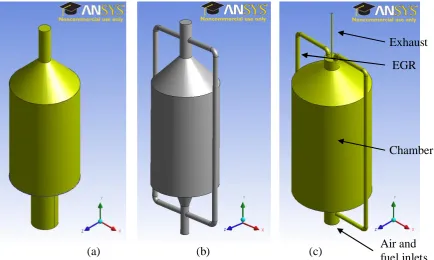
also the opening of the exhaust being very small. Improvement was made to the input of the EGR. The smooth corner to help the fluid flow into the EGR pipe was added (Figure 3(c)). The result was encouraging with the flow showing significant improvement. This method was then implemented at the EGR outlet at the bottom of the burner figure 4(b).
[image:7.595.89.524.163.423.2]
(a) (b) (c)
Figure 3. First combustion chamber model (a) No EGR (b) with 2 EGR pipe (c) with 2 EGR pipe and EGR inlet modified
Table 2. Typical data for furnace and burner in Figure 3(c)
Item Data
Fuel 0.5CH4 + 0.2H2 + 0.3CO2
Oxidiser Atmospheric air, heated to 800 K
Fuel inlet Round 1,256 mm2, 40~50 m/s each
Air inlet Annulus 5,140 mm2, 80~100 m/s each
Chamber size Diameter 375mm, Height 650mm
EGR 2 EGR with 386.9 mm2 each inlet
Mesh method Tetrahedrons (Patch conforming method) with 92,034 nodes and 421,172 elements
Radiation model Discrete Ordinate (DO) model. Absorption coefficient: Weighted Sum of Gray Gas (WSGGM) model.
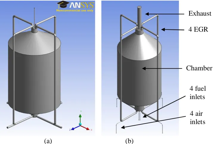
The next improvement was the addition of two more EGR pipes to become four. This new design can be seen in Figure 4. The gas entered the combustion chamber through four fuel inlet small pipes; each of them was 5 mm in diameter at 20 m/s to 40 EGR Exhaust
Air and fuel inlets
53
m/s depending on the need for lean or rich combustion. The gas then flew through to the centre of the bluff body burner and jetted in through the bluff body burner with the annulus opening of 24.3 mm2. Fresh air was injected at 80 to 100 m/s through 5 mm diameter at the side of each EGR pipe to induct the EGR to flow downward. The injected fresh air then mixed with the EGR gas. A more detailed burner and chamber specification is shown in Table 3.
[image:8.595.148.508.195.437.2]
(a) (b)
Figure 4. Final model with 4 EGR, (a) Air inlet internal diameter is 22 mm, (b) Air inlet internal diameter is 5 mm
Table 3. Typical data for furnace and burner in Figure 4(b)
Item Data
Fuel 0.5CH4 + 0.2H2 + 0.3CO2
Oxidiser Atmospheric air, heated to 800 K
Fuel Inlet 4 x 19.6 mm2, 20 m/s each Air Inlet 4 x 19.6 mm2, 80 m/s each
Chamber size Diameter 600mm, Height 860mm
EGR 4 EGR with 386.9 mm2 each inlet
Mesh method Tetrahedrons (Patch conforming method) with 111,975 nodes and 501,831elements
Radiation model Discrete Ordinate (DO) model. Absorption coefficient: Weighted Sum of Gray Gas (WSGGM) model.
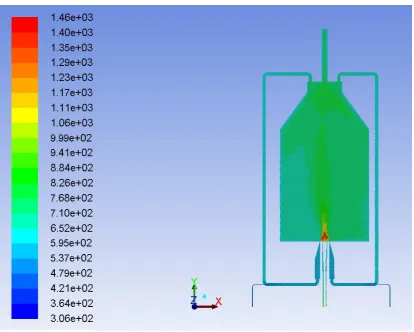
After the computational testing and analysis, the bluff body burner with 24.3 mm2 fuel inlet and 97.3 mm2 oxidiser inlets was chosen. The maximum
4 fuel inlets Exhaust
4 air inlets 4 EGR
54
temperature of the combustion is 1,540 K which is below the limit of the temperature for the rapid formation of NOx. The temperature of the combustion zone is 1200 to
[image:9.595.91.506.223.555.2]1540K (Figure 5). The inside wall temperature is about 750 to 800 K and the EGR flow is about 700 to 750 K. The flow for EGR is below 5 m/s since the opening for the chamber outlet is 176.6 mm2. This opening is relatively big in size compared to the total inlet size of 486.8 mm2. The ratio of inlet to outlet is 2.8. In order to increase this EGR flow, this opening can be reduced by increasing the EGR ratio. EGR ratio of 50% means half of the flue gas will flow back to the combustion chamber.
Figure 5. Combustion temperature in the chamber for Figure 4(b)
55
Figure 6. Velocity magnitude between -5.0 m/s to 5.0 m/s for figure 4(b) with gas inlet at 20 m/s and air inlet at 80 m/s.
56
Figure 7. Velocity in Y direction between 5.0 m/s to 0.1 m/s for figure 4(b) with gas inlet at 40 m/s and air inlet at 120 m/s and EGR is reverse flow.
Figure 8. Velocity in Y direction between -0.1 m/s to -5.0 m/s for figure 4(b) with gas inlet at 20 m/s and air inlet at 80 m/s and EGR is correct flow.
CONCLUSION
[image:11.595.165.430.384.584.2]57
fuel inlet and 97.3 mm2 oxidiser inlet was chosen. From the CFD result, the temperature of the combustion zone is 1200 to 1500K and the temperature inside the wall chamber and EGR pipe flow is about 750 to 800 K. The flow for EGR is below 5 m/s since the opening for the chamber outlet is relatively big: 15 mm in diameter. This EGR flow rate can be increased by reducing the exhaust flow rate.
ACKNOWLEDGMENTS
The authors would like to thank University of Southern Queensland (USQ), Ministry of Higher Education (MOHE), Malaysia and Universiti Malaysia Pahang (UMP) for providing financial support and laboratory facilities.
REFERENCES
Al-Seadi, T., Rutz, D., Prass, H., Kottner, M., Finsterwalder, T., Volk, S. and Janssen, R. 2008. Biogas handbook, Lemvigbiogas, University of Southern Denmark, Denmark.
AET. 2012. The formation of NOx, allied environmental technologies, Inc, http://www.alentecinc.com/papers, Accessed on 14 Jun 2012.
ANSYS. 2010. Ansys Fluent 13.0 Users’ Guide, ANSYS Inc., Canonsburg, US.
Awosope, I. and Lockwood, F. 2005. Prediction of combustion and nox emission characteristics of flameless oxidation combustion. IFRF Industrial Combustion Journal, Article Number 200501.
Bardina, J.E., Huang, P.G. and Coakley, T.J. 1997. Turbulence modeling validation,testing, and development, technical report, NASA, US. NASA Technical Memorandum.
BP. 2010. Statistical review of world energy (2010), British Petroleum PLC, Cedigaz, Paris, France.
BP. 2011. Statistical review of world energy (2011), BP PLC, Cedigaz, Paris, France Borjesson, P. and Mattiasson, P. 2008. Biogas as a resource efficient vehicle fuel.
Trends Biotechnol 26(1), 7-13.
Caresana, F., Comodi, G., Pelagalli, L., Pierpaoli, P. and Vagni, S. 2011. Energy production from landfill biogas: an italian case. Biomass Bioenergy 35, 4331-4339.
Cavaliere, A. and Joannon, M.D. 2004. MILD combustion. Prog Energy Comb Science, 30, 329-366.
Choi, C.E. and Baek, S.W. 1996. Numerical analysis of spray combustion with nongray radiation using weight sum of gray gas models. Combust Sci Technol, 115, 297-315
58
Chui, E.H. and Raithby, G.D. 1993. Computation of radiant heat transfer on a non-orthogonal mesh using the finite-volume method. Numerical Heat Transfer B, 23, 269-288.
Colorado, A.F., Herrera, B.A. and Amell, A.A. 2010. Performance of a flameless combustion furnace using biogas and natural gas. Bioresource Technology 101, 2443-2449.
Dally, B.B., Karpetis, A.N. and Barlow, R.S. 2002. Structure of turbulent non-premixed jet flames in a diluted hot coflow. Proc Combust Inst. 29(1). 1147–1154
Dally, B.B., Craig, R.A. and Mi, J.C. 2008. Dependence of flameless combustion on fuel-air injection pattern and their momentum ratio in a recuperative furnace. Ninth Asia-Pacific International Symposium on Combustion and Energy Utilization, Wuhan, China, pp. 35-40
Danon, B. 2011. Furnaces with multiple flameless combustion burners. PhD Thesis Effuggi, A., Gelosa, D., Derudi, M. and Rota, R. 2008. MILD combustion of methane
derived fuel mixtures natural gas and biogas. Combustion Science Technology 180(3), 481-493.
EIA (Energy Information Administration). 1999. Natural gas issues and trends, technical report DOE/EIA-0560(1999). US Department of Energy, Washington DC, United States.
EIA (Energy Information Administration). 2002. International energy outlook 2002, technical report DOE/EIA-0484(2002), US Dept. of Energy, Washington DC, United States.
EIA (Energy Information Administration). 2007 International energy outlook 2007, technical report DOE/EIA-0484(2007), US Dept. of Energy, Washington DC, United States.
EIA (Energy Information Administration). 2011. International energy outlook 2011, Technical Report DOE/EIA-0484(2011), US Dept. of Energy, Washington DC, United States.
EPA (Environmental Protection Agency). 1999. Nitrogen oxides (NOx), why and how they are controlled, technical report EPA-456/F-99-006R, Clean air technology center, US Environmental Protection Agency, North Carolina, USA.
Galletti, C., Parente, A. and Tognotti, L. 2007. Numerical and experimental investigation of a MILD combustion burner. Combustion and Flame 151(4), 649-664.
Galletti, C., Parente, A. and Tognotti, L. 2008. CFD simulations of MILD combustion.
In 8th European Conference on Industrial Furnaces and Boilers, Vilamoura,
Portugal.
Galletti, C., Parente, A., Darudi, M., Rota, R. and Tognotti, L. 2009. Numerical and experimental analysis of NO emissions from a lab-scale burner fed with hydrogen enriched fuels and operating in MILD combustion. Int. J Hydrogen Energy 34(19), 8339-8351.
Ghoniem, A.F. 2011. Needs, resources and climate change: clean and efficient conversion technologies. Progress in Energy and Combus. Sci. 37, 15-51.
59
furnaces by means of advanced diagnostics. European Conference on Industrial Furnaces and Boilers (INFUB), Porto, Portugal.
Hardestry, D. and Weinberg, F. 1974. Burners producing large excess enthalpies. Combustion Science Technology, 8, 201-221.
Hottel, H.C. and Sarofim, A.F. 1967. Radiative transfer. McGraw Hill, New York. Huang, J. and Crookes, R. 1998. Assessment of simulated biogas as a fuel for the spark
ignition engine. Fuel, 77(15), 793-801.
IEA (International Energy Agency). 2002. CO2 emission from fuel combustion:
1971-2000. Organization for Economic Cooperation and Development (OECD), Paris. IPCC. 2007 Contribution of working groups I, II and III to the fourth assessment report
of the intergovernmental panel on climate change.
Jonathan, P. 2006. Responses to questions on the design elements of a mandatory market-based greenhouse gas regulatory system. World Resources Institute, Washington.
Jones, W.P. and Launder, B.E. 1972. The prediction of laminarization with a two equation model of turbulence. International Journal of Heat and Mass Transfer 15, 301-314.
Katsuki, M. and Hasegawa, T. 1998. The science and technology of combustion in highly preheated air. Proc Combust Inst, 27(2), 3135-3146.
Launder, B.E. and Sharma, B.I. 1974. Application of the energy dissipation model of turbulence to the calculation of flow near a spinning disc. Letters in Heat and Mass Transfer, 1(2), 131-138.
Li, M., Rao, A., Brouwer, J. and Scout, S.G. 2010a. Design of highly efficient coal based IGFC power plant. J Power Source 195(17), 5707-5718.
Li, P.F., Mi, J.C., Dally, B.B., Richard, A.C. and Wang, F. 2010b. Effect of equivalence ratio and mixing pattern on flameless combustion, chinese society of engineering thermophysics conference. Chinese Society of Eng. Thermophysics, Guang Zhou.
Li, P.F. and Mi, J.C. 2010. Critical Reynolds numbers for realization of mild combustion in a recuperative furnace. 8th International Symposium on High Temperature Air Combustion and Classification, Poznan University of Tech. Press.
Liu, F., Becker, H.A. and Bindar, Y. 1998. A comprehensive study of radiative heat transfer modelling in gas fire furnace using the simple gray gas and the weight sum of gray gas models. Int. Journal of Heat and Mass Transfer, 41, 3357-3371. Maczulak, A. 2010. Renewable energy, sources and methods. Facts on File Inc., New
York, USA
Majda, A. and Sethian, J.A. 1985. The derivation and numerical solution of the equations for zero mach number combustion. Combust. Sci. Tech. 42, 185-205. Milani, A. and Wunning, J.G. 2007. Flameless oxidation technology. Adv. Comb. and
Aerothermal Tech. 6, 343-352.
Mi, J., Li, P. and Zheng, G. 2010. Numerical simulations of flameless premixed combustion in a recuperative furnace. China J Chem Eng 18(1), 10-17.
60
Orsino, S., Weber, R. and Bollettini, U. 2001. Numerical simulation of combustion of natural gas with high temperature air. Combust. Sci. Technol. 170(1), 1-34. Pacala, S. and Socolow, R. 2004. Stabilization wedges: solving the climate problem for
the next 50 years with current technologies. Science. 305(5686), 968-972.
Rehm, R. and Baum, H. 1978. The equation of motion for thermally driven bouyant flows. N. B. S. J. Res, 83, 297-308.
Scharler, R. and Obernberger, I. 2000. Numerical modelling of biomass grate furnace, European Conference on Industrial Furnaces and Boilers (INFUB), Porto, Portugal.
Szego, G.G., Dally, B.B., Nathan, G.J. and Christo, F.C. 2003. Design optimisation of a mild combustion furnace based on cfd modelling. Aust. Comb. Symposium
(ACS2011) and the 8th Australian Flame Days, Monash University, Australia,
Paper ID: P047.
Szego, G.G., Dally, B.B. and Christo, F.C. 2009. Investigation of the mixing patterns inside a mild combustion furnace based on CFD modelling. Aust. Comb. Symposium (ACS), University of Newcastle, Australia, Paper ID: 2009-28
Szego, G.G. 2010. Experiment and numerical investigation on a parallel jet mild combustion burner system in a laboratory scale furnace. PhD thesis, University of Adelaide, Australia
Tennekes, H. and Lumley, J.L. 1972. A first course in turbulence, MIT Press, United States of America.
Tsuji. H/, Gupta. A.K. and Hasegawa, T. 2003. High temperature air combustion. CRC Press, Boca Raton, FL.
Volk, T. 2008. CO2 rising; the world’s greatest environmental challenge, MIT Press,
Cambridge, Massachusetts, London, England.
Wilcox, D.C. 1998. Turbulence modeling for CFD. Second edition, Anaheim: DCW Industries.
Wünning, J.A. 1991. Flammenlose oxidation von Brennstoff mit hochvorgewärmter Luft. Chem.-Ing.-Tech. 63(12), 1243-1245.
Wünning, J.G. 1996. Flammlose oxidation von Brennstoff. PhD Thesis, Aachen
Wünning, J.A. and Wünning, J.G. 1997. Flameless oxidation to reduce thermal NO formation. Progress in Energy and Combustion Science, 23, 81-94.
NOMENCLATURE
CCS Carbon capture and storage CFD Computational fluid dynamics CO Carbon monoxide
CO2 Carbon dioxide
EGR Exhaust gas recirculation FGR Flue gas recirculation GHG Greenhouse-gas H2O2 Hydrogen peroxide
HC Hydrocarbon
HTOC High temperature combustion IEA International Energy Agency LCV Low calorific value
NOx Nitrogen oxides
OH Hydroxyl SOx Sulphur oxides