Development of a cyber attack simulator for network modeling and cyber security analysis
183
0
0
Full text
(2) DEPARTMENT OF INDUSTRIAL AND SYSTEMS ENGINEERING KATE GLEASON COLLEGE OF ENGINEERING ROCHESTER INSTITUTE OF TECHNOLOGY ROCHESTER, NEW YORK. CERTIFICATE OF APPROVAL. M.S. DEGREE THESIS. The M.S. Degree Thesis of Kevin C. Costantini has been examined and approved by the thesis committee as satisfactory for the thesis requirement for the Master of Science degree. Approved by:. ____________________________________ Dr. Michael E. Kuhl, Thesis Advisor. ____________________________________ Dr. Moises Sudit. i.
(3) Acknowledgements I would like to thank my advisor, Dr. Michael Kuhl, for his guidance and support throughout the development of this thesis. I would also like to thank Dr. Moises Sudit for his insight and expertise. I would like to thank Jason Kistner for providing me with an understanding of the cyber domain and the initial cyber attack simulation research performed for his thesis. I would like to thank Katie McConky for helping with the initial development of the java-based simulation model and user interface. I would also like to thank Greg Tauer for helping with some of the modeling and interface features. This research is funded through the National Center for Multisource Information Fusion.. ii.
(4) Abstract Computer networks are now relied on more than ever before for gathering information and performing essential business functions. In addition, cyber crime is frequently used as a means of exploiting these networks to obtain useful and private information.. Although intrusion detection tools are available to assist in detecting. malicious activity within a network, these tools often lack the ability to clearly identify cyber attacks. This limitation makes the development of effective tools an imperative task to assist in both detecting and taking action against cyber attacks as they occur. In developing such tools, reliable test data must be provided that accurately represents the activities of networks and attackers without the large overhead of setting up physical networks and cyber attacks. The intent of this thesis is to use operation research and simulation techniques to provide both data and data-generation tools representative of real-world computer networks, cyber attacks, and security intrusion detection systems. A simulation model is developed to represent the structure of networks, the unique details of network devices, and the aspects of intrusion detection systems used within networks. The simulation is also capable of generating representative cyber attacks that accurately portray the capabilities of attackers and the intrusion detection alerts associated with the attacks. To ensure that the data provided is reliable, the simulation model is verified by evaluating the structure of the networks, cyber attacks, and sensor alerts, and validated by evaluating the accuracy of the data generated with respect to what occurs in a real network. By providing accurate data with respect to network structure, attack structure, and intrusion detection alerts, the simulation methods used offer considerable support in developing tools that can accurately detect and take action against attacks.. iii.
(5) Table of Contents 1 2 3. 4. 5. 6. 7. Introduction............................................................................................................... 1 Problem and Scope ................................................................................................... 5 Background ............................................................................................................... 9 3.1 Computer Networks ............................................................................................ 9 3.2 Device Details................................................................................................... 13 3.3 Network Packets ............................................................................................... 14 3.4 Exploits ............................................................................................................. 17 3.5 Development of IDS ......................................................................................... 18 Literature Review ................................................................................................... 21 4.1 Modeling and Classification of Cyber Attacks................................................. 21 4.2 Simulation of Computer Networks ................................................................... 24 4.3 Information Fusion Techniques Applied to the Cyber Domain........................ 26 4.4 Object-Oriented Simulation Modeling ............................................................. 29 4.5 Cyber Attack Simulator Developed by Kuhl and Kistner ................................ 33 Simulation Model Structure................................................................................... 36 5.1 Modeling Intentions and Model Overview ....................................................... 36 5.2 Java Background............................................................................................... 40 5.3 Package Structure.............................................................................................. 42 5.4 Simulation Package........................................................................................... 44 5.5 Network Package .............................................................................................. 46 5.6 Attack Package.................................................................................................. 48 5.7 Visual Package.................................................................................................. 51 Network Methodology ............................................................................................ 55 6.1 Network Architecture........................................................................................ 55 6.2 Machines ........................................................................................................... 58 6.2.1 Subnets/Clusters........................................................................................ 61 6.2.2 Services ..................................................................................................... 62 6.2.3 Vulnerabilities........................................................................................... 63 6.3 Connectivity...................................................................................................... 65 6.3.1 Links.......................................................................................................... 67 6.3.2 Firewalls/Port Permissions ...................................................................... 69 6.4 Sensors .............................................................................................................. 72 6.5 Virtual Terrain .................................................................................................. 75 Attack Simulation Methodology............................................................................ 79 7.1 Modeling Traffic............................................................................................... 80 7.2 Available Actions.............................................................................................. 83 7.3 Attack Scenario................................................................................................. 85 7.4 Attacks .............................................................................................................. 88 7.4.1 Logical Exploits ........................................................................................ 93 7.4.2 Auto-Attack Parameters............................................................................ 94 7.4.3 Guidance Template ................................................................................... 96 7.4.4 Auto-Attack Methodology ......................................................................... 98 7.5 Event Handling ............................................................................................... 102 iv.
(6) 7.6 Scenario Results.............................................................................................. 106 7.7 Exporting Attack Scenarios ............................................................................ 109 8 Evaluation of Simulation Model .......................................................................... 111 8.1 Verification of Network Model ...................................................................... 112 8.1.1 Logically Verified Features .................................................................... 113 8.1.2 Visually Verified Features ...................................................................... 117 8.2 Verification of Attack Simulation................................................................... 120 8.2.1 Exploit Filtering...................................................................................... 121 8.2.2 Stage Progression ................................................................................... 123 8.2.3 Attack Parameters................................................................................... 125 8.2.4 Entity Routing ......................................................................................... 130 8.2.5 Noise Generation .................................................................................... 131 8.2.6 Alert Generation ..................................................................................... 133 8.3 Validation of Attacks and Alerts..................................................................... 135 8.4 Model Capabilities .......................................................................................... 138 8.5 Model Limitations........................................................................................... 142 8.6 Applications .................................................................................................... 144 9 Conclusions and Future Work............................................................................. 147 9.1 Conclusions..................................................................................................... 147 9.2 Future Work .................................................................................................... 151 9.2.1 Recommended Functionality Improvements ........................................... 151 9.2.2 Adjustments to Inputs.............................................................................. 153 References...................................................................................................................... 155 Appendix A: User Guide .............................................................................................. 158 A.1 Running the Simulator .................................................................................... 158 A.2 Building a Network......................................................................................... 160 A.3 Creating Attack Scenarios............................................................................... 168 A.4 Running a Simulation ..................................................................................... 173 Appendix B: Software CD............................................................................................ 177. v.
(7) 1 Introduction Computer networks have developed significantly over recent years. From college networks to business networks, nearly all aspects of their functionality have improved with regard to both speed and capacity. Because of these improvements, increases in the size and complexity of such networks have been common.. This growing size and. complexity is making the tasks of accurately monitoring network activity and maintaining all of the desired security standards more difficult for network administrators. The reliability that people and organizations expect from networks has also increased dramatically over recent years. There is an increasing dependence on networks to store needed information and provide for many of the operations that individuals and organizations rely on. For some organizations, the information and operations provided through a network are essential to the functioning of the organization. From banking firms to communication companies to healthcare, there is a strong dependency on computer networks to provide the information and functionality that these industries require (DeLooze, Graig, McKean, and Mostow, 2004). Due to the large size of, complexity of, and dependency on computer networks, the security concerns are escalating. Cyber attacks on such computer networks are becoming more common, and the threats of these attacks increases as organizations continue to store and access critical information through computer networks. Internetbased attacks especially are a major concern, and they are believed to account for about 70% of all malicious attacks on organizations. Furthermore, the occurrence of internal and remote attacks is becoming less common due to both the increased internet activity. 1.
(8) that organizations have and the ease of attacking through internet connections. Also, as traffic increases within the network itself, the specific actions of an attack become further buried within this traffic (Fuchsberger, 2005).. This can add to the difficulty faced by. administrators and sensing devices in effectively locating these attacks. Cyber attacks are becoming easier for less-trained hackers due to the abundance of useful applications and the availability of organization and network-related information that can be retrieved even from simple Google searches. As organizations leave sensitive information available to users outside of their network, search engines such as Google are able to find this information (through the use of bots) and display the information to any interested hacker that can come up with the proper search criteria (Kurtz, McClure, and Scambray, 2005). Also, tools and applications used for intrusions are becoming more powerful, requiring less knowledge from the attackers using them. For example, password guessing operations that had previously been manual are now being automated with a variety of tools. Such tools are becoming more available to the general hacking community, so attackers no longer need to be experts on the subject matter (Fuchsberger, 2005). These vulnerable computer networks have not been left defenseless, though. Intrusion Detection Systems (IDSs) have taken a role in helping network administrators find and follow network attacks. Intrusion detection offers a means by which network traffic can be monitored by a device, or sensor, in addition to being monitored by an administrator. This is done by the sensor determining if a particular packet of network traffic could perform or allow for a potentially malicious action. If so, an alert is generated. An IDS can provide warnings to indicate when malicious or suspicious. 2.
(9) activity is detected, and these warnings can help the system and the administrators defend against an attack.. Furthermore, an IDS can verify that changes to the security. configurations of a network do in fact provide additional security (Allen, Christie, and McHugh, 2000). Several different types of intrusion detection systems are available today, ranging from free open-source software to costly, specialized, and highlyintegrated proprietary systems. Although sensor alerts do indicate when something suspicious is happening, there still exists the need for individuals to look through these alerts (or some of these alerts) and try to determine what is really happening in the network. This process is where the idea of information fusion has recently been introduced into the cyber domain. Information fusion is a technique where data from many different sensors is combined with related databases of information to provide inferences that could not be determined from looking only at individual sensors (Hall and Llinas, 1998). Multi-sensor data fusion in the cyber domain is a fairly new concept that involves combining data from multiple IDS sensors to gain an understanding of network activities and events.. In the cyber. domain, determining the intent and threat of an attacker by looking at actions individually is a difficult task. Using information fusion as a tool allows for many actions to be analyzed together to gain a high-level understanding of the current network situation. The high IDS false-alarm rates (and the problems associated with them) as well as the lacking ability of most IDSs to gain a full understanding of a network’s current situation stress the need for improvements in the way these sensor alerts are handled. By utilizing information fusion techniques, there is potential for a new generation of robust intrusion. 3.
(10) detection systems to be developed that will provide situational information in addition to the information regarding individual actions (Bass, 2000). Even with the development of such intrusion detection systems using information fusion techniques, there is still the difficulty of testing and verifying that the systems provide the desired accuracy and functionality. Obtaining significant amounts of IDS sensor data is difficult, and setting up physical networks to perform such tests requires significant time and money. Also, the variability of networks as well as the value of information stored on such networks can make the process of accounting for the different network structures nearly impossible to handle using a physical setup. The development of intrusion detection systems utilizing information fusion needs to be aided with a significant amount of reliable data with which to verify and validate the systems’ performance.. 4.
(11) 2 Problem and Scope Providing security in a private network is one of the leading challenges that organizations are facing with respect to the management of information. Companies often keep proprietary and personal information stored on a private network, and these companies do this with the intent of the information only being accessed by reliable individuals. Frequently, though, hackers (with either individual motives or affiliation with competing organizations) will find such information of great value and manage to pry their way into the private network to either obtain or corrupt the desired information. Most private networks have some form of internet connection, which allows for webbased attacks to be a threat. Hackers will track down such networks and determine the vulnerabilities and the exploits that will assist them in gaining access into such networks. Although security measures within private networks are improving, finding all of the vulnerabilities and keeping the various security measures up to date is a challenging task for company network administrators, and those planning to attack a private network are counting on just this. Furthermore, new exploits will always be found before security measures are made available to deal with them (Kurtz, McClure, and Scambray, 2005). Due to the difficulty of maintaining security in the world of private networks, the importance that private networks and the information stored on them have to companies and organizations around the world, and the frequency at which hackers will attack such networks to obtain the desirable information, the scope of this research will deal with security in private networks. The development of network security tools that make use of information fusion techniques are a significant step forward in reliably securing a private network.. 5.
(12) However, as noted previously, there is still much to be done in this realm due to the difficulty of developing robust information fusion systems and verifying that they accurately recognize attacks. In fusing together information from multiple IDS sensors, a critical factor is to have an understanding of whether the fusion engine being developed sufficiently detects the attacks taking place. Attack and sensor data that is provided during the development stages of information fusion engines can significantly help the developers confirm their functionality. To verify that attacks are sufficiently detected, a network could be setup where known attacks are performed and sensors are collecting related alerts from the actions involved. However, this option creates a substantial expense for the developers, and such a setup also does not account for the great variability in the intent and styles of attacks that could possibly occur. For these reasons, the use of simulation modeling is suggested to accurately portray both the flow of an attack through a network and the IDS alerts associated with that attack (Holender, Stotz, and Sudit, 2006). Simulating the attacks and the generation of IDS alerts allows for significant amounts of attack and sensor related data to be generated quickly with little or no cost. Furthermore, this simulation will allow for networks of varying sizes and structures to be easily modeled and used in developing the attack and sensor data. By providing simulated cyber attack data, information fusion system developers will have the potential to test their fusion engines across a wide range of scenarios. A simulation model and methodology has been developed by Kuhl and Kistner (2005) to provide attack and sensor data for use by fusion engines. This simulation model allows for varying network sizes and configurations, but there are considerable limitations in accurately portraying private networks and attacks on those networks. The. 6.
(13) goal of this thesis is to provide a simulation model and methodology that addresses the limitations and issues with the existing model and improves the accuracy and performance of the model in generating valid attack and sensor data. This thesis will expand upon the simulation model developed by Kuhl and Kistner (2005). There are many important criteria in developing a valid attack simulation model with high accuracy and strong performance. These, broadly, include allowing attack scenarios to be run and modified easily, providing significant control of the modeled network, producing valid and detailed attack and IDS related data, and allowing for multiple applications in modeling intrusion detection systems. With respect to the ease of modifying and running scenarios, the simulation model should provide the user with intuitive controls, give options with regard to how output data should be generated and dealt with, and graphically display the aspects of the network and the attacks. Accounting for all of these considerations, there will be less possibility of the resulting model being improperly used or generating data that the user did not intend to generate. In providing significant control of the modeled network, the simulation should allow for a wide spectrum of details to be at the discretion of the user. This includes both the network topology and the individual device attributes.. For instance, the simulation. should provide the ability to specify the vulnerabilities of a network device that will reflect what attack actions are available against the device. Also, the simulation should allow for IDS sensors and IPS tools to be easily added to the network devices. Having these options will allow the model to better reflect the slight differences that exist between actual network devices. With respect to producing valid and detailed network data, the attacks created and the alerts generated should be accurately portrayed. The IDS. 7.
(14) sensor data should be representative of the output that actual sensors provide. The attacks that the simulator creates should follow a logical attack step progression based on existing modeled attack templates. To allow for the simulation model to be valuable to multiple applications in modeling intrusion detection systems, the model should have parameters setup to handle a variety of user defined information and methods established by which new (or different) IDS sensors can be added and used in the model.. 8.
(15) 3 Background The methodologies presented in this thesis require an understanding of basic networking principles. This chapter reviews some of the basic networking principles referenced in the network and attack simulation methodology to give the reader a clearer understanding of what is being accomplished. First, an overview of network architecture is provided in section 3.1. Section 3.2 gives a more detailed description of the network devices. Section 3.3 describes network packets and presents the functionality of the packets. Section 3.4 gives an overview of the exploits that hackers used to perform malicious activity on a network. Lastly, section 3.5 discusses the development of intrusion detection systems (IDSs) and the role these systems play in providing a level of security in a network. 3.1. Computer Networks A network generically represents any set of devices that are connected together. through some means in order to communicate and share information. A computer network focuses on computers being interconnected for this purpose. Networks can range from a simple single connection between two computers to a vast network of cables and routers that connect thousands or even millions of computers (such as the Internet). This networking review, though, will focus specifically on local area networks (LANs) where all of the network devices are located in roughly the same geographic location. In a typical LAN, the devices are managed by the same group or company and are connected at high speeds. This section provides a brief overview of the devices used in a computer. 9.
(16) network, the connections made between these devices, and the typical structure or topology of LANs (Barrett and King, 2005). The primary devices in a network are computers. With respect to a company network, these computers are used to manage data and perform essential and/or beneficial business functions. For these purposes, two broad categories of computers are used: servers and clients. A server is a computer specifically designed to store and share resources among other computers in the network or even in a different network through connection to the Internet. A client (or host) is a computer that can function individually or use resources provided by servers. Each computer in a network is provided with a unique MAC (machine access control) address that is used to reference the computer (Barrett and King, 2005). Although direct connections can be made between computers, some additional network hardware is typically provided to allow multiple (and possibly more complex) connections to a computer. This hardware is in the form of a routing device, which can be connected to several machines as well as several other routing devices. Figure 3.1 displays how these routing devices are used to connect computers in a network. In this figure, both Computer A and Computer B are able to communicate with the fileserver. Depending on the routing device used, a certain level of functionality will be provided that can include logic used to manage the communication capabilities and limitations between computers in the network (Barrett and King, 2005).. 10.
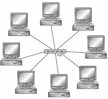
(17) Figure 3.1: Communication between Multiple Computers Different types of routing devices include hubs, switches, bridges, and routers. Hubs provide the least functionality and simply retransmit all received information through every other connection made with the hub. A bridge is used to send information between different LANs, and a bridge includes some functionality for identifying the destination of the information. Switches send information to the specific MAC address (computer) in the network that the information is intended for. A switch also includes some functionality to filter out certain types of communications. Routers are used to send information to a specific computer in the network or to the Internet. A router includes tables that store which routes can be used in allowing one computer to communicate with another computer. A router is also integrated with the functionality for filtering out certain types of communication (Barrett and King, 2005). Keeping an organized structure for the device connections made within a computer network is an important part of setting up and managing a network. Computers with both a similar functionality and physical location are typically connected with the same routing device. The illustration created by Barrett and King (2005) and displayed in Figure 3.2 shows a common method used to connect computers in this way (known as a star topology). In this type of topology, each computer has one segment connected to the. 11.
(18) routing device. With this method, an interruption in one segment will not affect the other segments. The routing device can then be connected to other routing devices within the network to provide communication between these computers and another group of computers (Barrett and King, 2005).. Figure 3.2: A Star Topology for Connecting Computers (Barrett and King, 2005) Another common approach used in setting up a computer network is to separate the externally accessed servers from the computers and servers intended for internal company functions. For example, an organization may have a web server that provides the company’s website and an FTP server that allows files to be transferred to different organization locations or even different organizations. These two servers can be kept on a separate portion of the network in order to provide a more secure setting for the remaining internal computers and servers. Figure 3.3 displays this type of configuration. The two external servers are connected to a router that can directly communicate with the Internet. The remainder of the network is connected to internal routers that provide some security through the means of firewalls, which will be explained in section 3.2.. 12.
(19) Internet. Web Server FTP Server. `. `. `. Internal Hosts and Servers. Figure 3.3: Example Network Configuration 3.2. Device Details Both computers and routing devices have certain characteristics that effectively. guide what type of communication can occur. For computers, such characteristics include the type of computer, the operating system used on the computer, and the services running on the computer. For routing devices, the primary characteristic is the set of firewall permissions. This section provides more details regarding these four device characteristics. The type of computer refers to whether the computer represents a host (client) or a server. Hosts and servers have differences in the way that they communicate, and these differences need to be recognized and considered when developing communication rules. The operating system used by the computer indicates the underlying software used to run applications on the computer. Different operating systems, such as Windows and Linux, typically use a special set of protocols (or communication mechanisms) to transfer information. Services represent the specialized software running on a machine to provide. 13.
(20) a particular functionality that is not possible with the operating system alone. These services help the operating system communicate with applications running on the computer. For example, an FTP service allows specific files to be uploaded to and downloaded from a file server. Many services have specific protocols that must be used in order for communication to occur with the service (Barrett and King, 2005). The firewall permissions stored on some routing devices indicate what type of communication is allowed along a certain communication path. Typically, these permissions are set up to either allow only certain types of communication or block only certain types of communication. For each specific path through a router, the firewall permissions will contain a listing of what protocols and computer ports are allowed or banned. A computer port represents a specific mechanism used to establish a connection with another computer (or data source). Each computer has thousands of ports that can be used to establish a communication path. This wide range of ports allows for multiple communication paths to be established at the same time on a computer. Firewall permissions are typically setup such that only a small subset of ports is available to be used. The specific port used in sending a particular piece of information will commonly depend on the service associated with the information (unless the information is not associated with a service) (Barrett and King, 2005).. 3.3. Network Packets The components, or devices, within a computer network communicate and send. data through the use of “packets”. Packets contain a pre-defined amount of data with additional headers that indicate how the data will be handled. Simple communication. 14.
(21) between two machines may only require a single packet while transferring a large file between two machines may take hundreds of packets. When more than one packet is used, the data within the packets must be pieced back together to form the original data stream (file). The packets flowing through a computer network are also referred to as the network traffic. The functionality for handling packets in a computer network is provided by a set of protocols known as TCP/IP. This set has four layers of protocols that are all an essential part of allowing computers to communicate with each other. A breakdown of the protocols is shown in Figure 3.4. The lowest (physical) layer is the Ethernet, which provides the physical connection between computers and the electrical signals that represent packets. The remaining three layers each have a specific header, or set of instructions, in the network packets (Crothers, 2003).. Figure 3.4: TCP/IP Protocol Suite 15.
(22) The Network layer, using IP and ICMP, provides the routing of the packets, which is essentially handling how the packets get from the source computer to the destination computer through the available Ethernet connections in the network. This layer makes use of the IP addresses of computers in order to route the packets. The IP header includes the source and destination computer for a particular packet, and each network linking device (router, hub, etc.) uses this information to send the packet through the appropriate link in the network (Crothers, 2003). The transport layer, using the TCP and UDP, provides the packet handling functionality. This functionality includes breaking a file or stream of data into packets at the source computer and restructuring or re-ordering the packet data to form a full data stream at the destination computer. Both TCP and UDP have a wide range of ports that packets can be sent or received by. Usually, though, a specific set of source and destination ports (TCP or UDP) is used for a packet relating to the machine service responsible for the packet. The transport layer header included in the packet indicates which type of protocol (TCP or UDP) and which port number to use (Crothers, 2003). The application layer is used to interpret and allocate the data to a specific machine service and service protocol, such as a web server (HTTP), a mail server (POP3), a file server (FTP), or some other service. The service can then make use of the information provided by the packet data. The application layer header indicates which type of service-specific protocol to use (Crothers, 2003). At the source computer, the packets are assembled starting with a particular service. The service pulls together all of the data that needs to be sent, known as the packet payload, and adds the application layer header. The transport layer then breaks. 16.
(23) this lumped data into several packets of equal (or near equal) size and includes an additional header pertaining to the protocol and port combination to use along with the order of the packets. The network layer adds another header to each packet indicating the source and destination IP addresses that the packet needs to be routed between. Lastly, the physical layer provides a dynamic header that indicates the source and destination MAC addresses for each packet at each link along the path taken, meaning that the header will change each time the packet moves through a different link (Crothers, 2003). 3.4. Exploits Exploits represent the actions that hackers perform to attack a network. While an. attack is considered an attempt to bypass some sort of computer security measures, an exploit is considered a step within an attack used to take advantage of a specific flaw or vulnerability in the network. An attack can consist of many different exploits performed in sequence. A successful attack, that violates the security policy of a system, is considered an intrusion. Weaknesses in the network that are subject to being exploited are considered vulnerabilities. Vulnerabilities commonly exploited by hackers can be broken down into three categories: development and design problems, management problems, and trust abuse. Development and design problems refer to software coding errors or architectural application issues that allow for an application (or the system running the application) to be used in a means that was not intended. This type of vulnerability is the most commonly exploited vulnerability in network attacks. Management problems refer to improper network configurations or policies that allow hackers to gain access to points in the network believed to be protected. This type of vulnerability is common with. 17.
(24) inexperienced network administrators. Lastly, trust abuse refers to the misuse of privileges given to an individual. This type of vulnerability requires that the hacker already has some level of allowed access to the network. Internal-based attacks (as opposed to internet-based attacks) will commonly exploit the trusted user abilities (Crothers, 2003). Both development/design problems and management problems are typically exploited by breaking (or at least bending) the rules of the TCP/IP protocols. Such exploits can be in the payload (data) of the packet or in one of the packet headers. Exploits associated with software (or service) design vulnerabilities tend to either include malicious code within the packet data or take advantage of the application header and the application protocols. Exploits associated with the network configuration vulnerabilities will typically take advantage of the transport layer protocols or the IP layer protocols. For example, an internet-based hacker can spoof a packet’s source IP using an IP address of the internal network. This activity effectively takes advantage of the IP layer to make the packet appear to be coming from a trusted internal source, and the destination computer will most likely accept the packet data (Crothers, 2003). 3.5. Development of IDS An intrusion detection system (known as an IDS) offers a way for network. administrators to monitor what type of actions are occurring within a network and attempt to take action against attempted intrusions (attacks). This system works by correlating a set of actions with known vulnerability exploits. The modern techniques used to identify and correlate cyber attacks are significant improvements over the original techniques. Initially, the only real method to locate. 18.
(25) malicious activity involved a dedicated administrator that would sit in front of a console and monitor the network activities looking for suspicious actions. The increases in network size and activity drove this method of detection to become far too difficult for detecting attacks in real-time. Thus, the use of audit logs became prevalent to keep track of and store the network activity without the need for individuals to continuously monitor the activity. This method, though, still resulted in a vast amount of information for administrators to manually sort through. Often, this information would only be used as a forensic tool when an actual incident had occurred and the administrators wished to pinpoint what had caused the incident. Therefore, the method of direct observation and response has become less effective over time (Kemmer and Vigna, 2002). As a next step in identifying cyber attacks, intrusion detection systems (IDSs) have been developed to automatically detect suspicious-looking network traffic. These systems offered a relief from the increasing amount of network traffic that needed to be looked through. Intrusion detection systems (specifically, host-based IDSs) started out by reviewing audit data as the data was produced in order to provide network administrators with only information that could potentially be related to an attack, thus filtering out information regarding the typical, harmless network traffic (Kemmer and Vigna, 2002). As the IT security industry developed over the years, the use of intrusion detection systems significantly increased, and the processing rate of these systems improved as well. Network-based IDSs were introduced to monitor the actual network traffic instead of the log files produced by a specific host. These systems identify attack actions by matching attack patterns in the TCP and IP packet stream, and they have a distinct advantage over host-based IDSs in that they are not associated with a device that. 19.
(26) could potentially be a target itself. As processing power has improved, these systems have become capable of monitoring the network traffic in “real-time” and triggering alerts as suspicious activity is identified. Market demands further drive this industry to develop full-fledged software corresponding to the IDSs, with a wide array of capabilities in monitoring and organizing the alerts generated by the IDS sensors (Fuchsberger, 2005). Intrusion detection systems, even with improved accuracy and processing, still only account for part of the methodology needed to actually defend a network against the attacks. These systems can determine the cause of an attack (and possibly the intent), but the IDSs alone do not take the measures to stop such an attack. To perform this function, intrusion prevention systems (IPSs) have been developed in an attempt to react to the detected malicious activity. Since these IPSs are actually capable of thwarting some attacks, the demand for such systems is becoming stronger than the demand for simple IDSs (Fuchsberger, 2005). However, the majority of current IPSs available do little in terms of actually identifying an overall attack. Instead, a methodology similar to the IDSs’ methodology is used where the network traffic is inspected to look at individual packets and “reflex”-type actions are performed when suspicious activity is identified. Therefore, many common intrusion prevention systems are really only capable of reacting to individual attack steps rather than entire attacks.. 20.
(27) 4 Literature Review There are three primary areas of research related to the problem being addressed, which include the modeling and classification of cyber attacks, the simulating of computer networks, and the use of information fusion techniques in the cyber domain. Although there is some overlap between these topics, the combination of all three has only recently gained attention.. Therefore, there is a great deal of opportunity in. identifying some of the leading issues across these fields and providing a methodology that effectively addresses these issues. This section reviews some key research that has already been performed in these fields. Apart from these three areas of research, the development of object-oriented simulation models is discussed to provide some preliminary concepts that helps establish an effective object-oriented simulation model for the modeling required in this thesis. This discussion includes several different modeling approaches explored by researchers. Also, this section concludes by discussing both the details and limitations of an existing cyber attack and intrusion detection simulator developed by Kuhl and Kistner (2005). This existing simulator is important because the research performed in developing the simulator has served as a basis for the initial work accomplished by this thesis. 4.1. Modeling and Classification of Cyber Attacks An effective means to understanding cyber attacks is through classifying the. attacks and modeling the attack progression.. This involves carefully observing the. actions associated with a known attack to gain an understanding of the attacker behavior. Fortunately, there has been significant progress made in modeling attacks.. 21.
(28) Dougherty and Gonslaves (2006), for instance, developed an adaptive cyberattack modeling system to assist in testing software protection. Previously, a team of subject matter experts (SMEs) were required to mimic the actions typically associated with hacker attacks in order to evaluate and validate their software protection methodology. This method, though, adds significantly to the cost and time required for such a project, and the method is not really appropriate for the large numbers of scenarios which need to be thoroughly tested.. The research performed by Dougherty and. Gonslaves found that developing accurate models of cyber attacks had the potential to substantially reduce the cost and time required. Through this modeling, three primary categories of attacks were identified: web-based application attacks (considered the most vulnerable due to the substantial number of tools at the hacker’s discretion), client-server application attacks, and stand-alone system attacks (which are the hardest to implement). Also, the models implemented a Bayesian belief network approach to mimic the reasoning made by hackers. Although the modeling done through this research only extended to that which was needed for testing the software protection, the methodology is a good representation of what is becoming necessary for any type of security tools. Other researchers have looked into modeling attacks by analyzing isolated IDS alerts associated with attack steps. For example, Cheung, Fong, and Lindqvist (2003) developed a project called “Correlated Attack Modeling” (CAM) where attack scenarios are modeled by observing actual IDS alerts. These IDS alerts can generally be associated with a specific attack step (usually an exploit of some sort). Although this allows for actual attacks to be used in developing attack patterns, many IDS alerts could be false positives and thus affect the modeling process. Furthermore, some attack steps may be. 22.
(29) missed altogether or could be temporally distributed enough that piecing together an attack (let alone add to an attack pattern) becomes a difficult task. Also, higher-level research has been done to identify the typical sequence of the different exploits that a hacker can perform.. Holdender, Stotz, and Sudit (2005). developed a graph-based template that makes use of graph theory techniques to designate what types of attack actions or exploits are necessary before other certain types can be performed. This development began by first grouping known exploits into categories or “stages” based on what type of activity was necessary before these exploits occurred and what type of activity could be performed afterward. An adjacency matrix was then developed to correlate the different stages, indicating what stages can occur after an exploit from a given stage has occurred for all of the stages in the template. A simplified directed graph of this attack exploit template is displayed in Figure 4.1. The nodes containing S0 through S9 represent the ten stages of attack exploits, while the edges (arrows) represent the precedence of stages. For instance, an intrusion-type exploit from stage 1 (where the attacker gains user access on a device) will only occur after a reconnaissance-type exploit from stage 0 has been performed (where the attacker obtains useful information about the device).. By categorizing possible exploits of known. vulnerabilities into one of the stages, the process of modeling an attack becomes simplified in that only the stages of the attack truly need to be modeled as opposed to the vast amount of exploits that would need to be considered otherwise. Due to these advantages, this graph-based template was used in the simulation model developed by Kistner (2006) to allow for attacks to be automatically simulated based on a set of parameters.. 23.
(30) S0. S1 S2 S3. S5 S6 S7 S8. S4. S9. Figure 4.1. Directed Graph of Stage Precedence (Holender, Stotz, and Sudit 2005) 4.2. Simulation of Computer Networks When simulating the progression of attacks through a network and in generating. typical IDS alerts within a network, providing a simulated network structure to work with is a necessity. Even though these processes could be established on a physical network, the large overhead costs and long testing times make such an arrangement highly undesirable. Furthermore, covering the large variety of network setups and sizes with physical means is nearly impossible. Simulation modeling allows for numerous setups and significant structural changes to be made quickly. Although other simulation models have been developed to portray the cyber attack process, the generation of IDS alerts, or both of these functions, these models lack the functionality and modularity necessary to generate the proper input needed for development of information fusion tools for the cyber-attack realm. Garg, Kwiat, and Upadhyaya (2006) developed a framework (known as SimCo) for measuring the capabilities of security mechanisms in detecting attacks. Inaccuracies among intrusion detection systems and other security systems can have a significant impact on organizations; thus, identifying where flaws lie within such systems is crucial.. 24.
(31) The framework developed included a platform for simulating complex attacks along with templates for both security detection mechanisms and for attacks. However, even though IDSs were included, this project was focused more on evaluating differences among the security systems rather than providing IDS alert data. The IDSs and other security systems were modeled in much more complexity than is really necessary for a simulation specifically requiring alert data.. In most cases, the entire functionality of the. IDS/security system was modeled. This functionality focused mostly on the internal workings of the sensors, which included modeling the means by which attack steps were identified and correlated to alerts. For the simulation methodology needed in this thesis for strictly generating IDS alerts, the means by which the alerts are generated is irrelevant as long as the alerts are representative of the corresponding IDS alert format. DeLooze et al. (2004) have also developed a simulation methodology to model the combination of cyber attacks and security systems. They developed a simulation model called “The Virtual Network Simulation” to assist in education and training courses for individuals pursuing careers in network security. The simulation model developed includes a vast amount of network devices (including IDSs) that can be setup at the user’s discretion, and the model interjects simulated attacks into these networks. However, since this system is setup as a training tool, the model requires consistent interaction with an individual to monitor, make adjustments to, and handle problems occurring within the simulated network. Therefore, this tool is also not well designed for data generation associated with the attacks and IDS alerts. Significant work has also been accomplished in developing a simulation model for both generating attacks and producing associated IDS alerts. Kuhl and Kistner (2005),. 25.
(32) through the use of the commercial simulation package ARENA, developed a simulation structure that allows for computer networks to be modeled and cyber attacks to occur within the networks and produce alerts for corresponding IDS sensors included in the modeled computer network. Kistner (2006) further expanded upon this work to develop more detailed attributes for the network devices and provide a methodology for automatically generating attacks based on a set of parameters. Section 4.5 provides a more detailed discussion of the research performed by Kuhl and Kistner (2005) and Kistner (2006). 4.3. Information Fusion Techniques Applied to the Cyber Domain Information fusion techniques, as recently applied to cyber security issues, have. the potential to identify useful trends and a significant amount of information about hacker attacks based on data provided by IDS sensors. In general, multi-sensor data fusion refers to the techniques used to combine data from multiple sensors along with related information from databases and templates to determine certain information about the system of interest. The use of multiple sensors allows for more accurate information that accounts for a wider spectrum of the system, in addition to the simple statistical advantage of having more data points to base a decision on. This information fusion technique has previously been used in surveillance mechanisms, guidance and control of vehicles, monitoring machinery, medical diagnosis, and other military and non-military purposes (Hall and Llinas, 1998). The generic process of fusing data has five specific levels of functionality defined by the Joint Directors of Laboratories (JDL). Figure 4.2 depicts these levels with respect to a variety of multi-sensor data fusion applications. Level 0 refers to the pre-processing. 26.
(33) of data, where data most pertinent to the current situation is filtered from a large set of raw data.. Level 1 represents Object Refinement, where data is transformed for. consistency and several attributes of the objects are identified and classified. Level 2 represents Situation Refinement, where relationships are developed between objects and events through incorporation of environmental information and previous (a priori) knowledge.. Level 3 represents Threat Refinement, where the current situation is. projected into the future to determine potential threats and vulnerabilities to the system, as well as opportunities available. Level 4 represents Process Refinement, where the long-term data fusion performance is monitored, improvement opportunities are identified, and adjustments are made to the system to achieve some desired effects (Hall and Llinas, 1998).. Figure 4.2: JDL Fusion Levels (Hall and Llinas, 1998) Holender, Stotz, and Sudit (2005) have developed an “Information Fusion Engine for Real-time Decision Making” (called INFERD) with the capabilities necessary to be. 27.
(34) used with IDS alert data in the cyber-domain. Essentially, the alerts produced by IDS sensors are treated as data points that INFERD can accept as input in order to piece together the information to identify attacks or malicious activity occurring in the network. Therefore, INFERD can provide some awareness with regard to the current state of the network (in real-time) that alert data is received from. With respect to the JDL fusion levels, INFERD accounts for a combination of Level 1 and Level 2 fusion. In addition to the data input into the engine, INFERD also requires attack templates along with some information regarding the network topology (which refers primarily to the structure of the network being assessed). Although the intent of this engine is to correlate actual alerts to determine attacks, the process is still in development and needs extensive testing. Since actual IDS alert data is challenging to obtain, as discussed previously, and since there is no faultless method to evaluate whether the engine is perfectly identifying the situation, the use of simulation to provide representative IDS alert data is very beneficial in this spectrum of the fusion process. Also, by assisting the development of INFERD, the use of simulation can also provide benefits for the higher levels within this fusion process. For example, TANDI, a fusion engine used within Level 3 of the fusion process, provides predictions of the attacker’s next moves (essentially, the threat imposed by the hacker) (Holender et al., 2006). With a simulation model, we will know exactly what the attacker’s next moves are, and this knowledge can be compared with the output that TANDI provides to give a measure of TANDI’s effectiveness. The simulation could even go beyond this to allow an engine or methodology focused on process refinement (Level 4 fusion) to update the simulation model in real-time and evaluate how well the entire fusion system is functioning within a network.. 28.
(35) 4.4. Object-Oriented Simulation Modeling The use of an object-oriented approach to simulation modeling has many. advantages over a procedural approach. The ability to re-use and extend objects is a central feature and advantage to developing an object-oriented framework. Also, since objects are modular, the information associated with each instantiation of an object is held in only one location, with references to the object’s location when needed (Bischack and Roberts, 1991). Furthermore, with an object-oriented simulation focusing on representing objects, the computations and modeling logic can be divided among objects (classes). This delegation of modeling functions provides a more organized structure than would otherwise be possible with procedure-based modeling (Joines and Roberts, 1998). The first step in developing an object-oriented simulation model is to devise the appropriate software architecture concept. This includes a broad definition of how the model and the simulation aspects and controls will interact at a high-level. Sarjougian and Singh (2003) recommend the use of three separate frames within the simulation architecture to provide the needed interaction. These include a model, control, and view frame. The model frame in this situation composes the application functionality and handles the states of objects being represented. The control links user actions to model changes and selects specific “views” or states of the system to present to the user. The view represents the user side of the architecture, where the model is rendered and user gestures are provided. In developing a discrete-event simulation architecture, Brunner and Schriber (2005) indicate the importance of providing a “transaction-flow world view,” where a discrete amount of traffic or transactions are moving from point-to-point (or object to object) within a system in order to change the state of the system. Numerous. 29.
(36) approaches can be taken to provide this type of interaction, but the key is to establish a framework that will clearly define this transaction-flow. The structure for the classes in the desired simulation framework is another major consideration. Darmont (2000) proposes the use of a centralized simulation class that ties together all aspects of the system. The class includes a link to a scheduler class that handles the various discrete events that occur during the simulation. An event manager class is used to provide implementation of the different events within the simulation model. Also, the resources involved are handled through a resource class linked with the simulation class. This approach allows for the simulation class specifically to handle the transactions involved in the simulation; although, there is some redundancy with having both a scheduler and event manager class. Joines and Roberts (1998) provide a detailed structure by which to setup a simulation class hierarchy. The top of this structure includes an abstract class with properties and methods available to all simulation components. Children (sub-classes) of this class include a random class that provides random number generation and distributions, a statistics class to calculate model statistics based on the attributes accessible to the abstract class, and a simulation element to model and run a simulation.. The simulation element has five primary child classes that. represent the main modeling components. An events class is used to organize and implement the events defined during the simulation run. A process class is used to handle specific resource manipulating processes. An entities class is used to represent the different transactions that move through a system. A nodes class represents specific points or objects in a system that the entities enter and exit. Lastly, a choices class handles the logic needed to manipulate transactions in the system. This overall approach. 30.
(37) is broad enough to account for numerous types of systems that could be modeled through discrete-event simulation. Furthermore, the inheritance structure allows for the common simulation properties to be easily accessible. The real functionality of the simulation model itself, though, is still left to the objects. The simulation structure and class hierarchy are only useful if the individual objects involved are given the appropriate methods and attributes needed to effectively interact and change the model state. Baezner and Lomow focus on three basic criteria to provide the general needs of a simulation: an entities class, an events class, and a property to keep the simulation time. The entities class is used to model any of the physical objects or processes being modeled, and the events class is used to schedule and trigger the actions of all entities. The simulation time is appropriately updated through the events. Joines and Roberts (1998) further extend their class hierarchy recommendations by providing specific information about the classes involved. Three classes of interest in the hierarchy are the events, entities, and nodes classes. The entities class provides the elements that are to be moved throughout the system to invoke changes. The entity class includes methods to obtain the entity’s creation time, status, current location, and unique identifier (ID). The nodes class is used to model different nodes or locations within the modeled system. This class allows for a network of nodes to be established and provides methods to obtain the type of node, identify entities at the current node, list nodes within the system or network, and identify the node ID. There are also methods triggered when an entity enters a node or leaves a node. The events class contains methods to set and get the event time, process the event, and manage the. 31.
(38) events and what they are associated with. The next section will provide more details regarding to the handling of events. The majority of discrete-event simulation approaches rely on methods for handling a series of defined events. Typically, events are added to an ordered list in which each event is handled separately based on the time. In this setup, a simulation clock keeps track of the time and only advances in discrete amounts when all of the events for the current time are finished processing (Brunner and Schriber, 2005). In the structure proposed by Joins and Roberts (1998), events are pulled off of a calendar and trigger appropriate transactions in the model. These transactions (entities) trigger node events and, thus, allow for a fairly decentralized method of logically handling each event. Lin, Sheu, and Yeh (1996) propose an event handling method that focuses on sending each current event to a specific event handling routine (either a class or method) to handle the logic associated with that event. Although this can simplify and organize the responses to events, the logic required to check the routine could be avoided when utilizing the overloading features of class inheritance. Numerous applications have been developed to illustrate and utilize the power that object-oriented simulation has to offer.. One such application, YANSL, was. developed by Joines and Roberts (1998) as an illustration of their proposed objectoriented simulation architecture. YANSL includes both transaction and resource entities moving through a network of node objects. The node objects consist of a variety of both departure and destination node types with different functionality, including a source node (to create entities), queue node (to hold entities), activity node (to modify entities), and sink node (to remove entities). The event handling triggers methods in the departure and. 32.
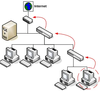
(39) destination nodes to be appropriately triggered and adjust the movement and attributes of entities in the model. YANSL still has significant modeling and statistical limits, but the extensive use of class inheritance effectively reduces the amount of logical statements and decisions to be made, and allows for decentralized control of the simulation. 4.5. Cyber Attack Simulator Developed by Kuhl and Kistner The simulation model developed by Kuhl and Kistner (2005), known as the Cyber. Attack Simulator, was created using ARENA, a commercial simulation modeling software developed by Rockwell Software. Within this software, a custom template is provided to represent the network devices that needed to be modeled. This template includes the connectors (routers or switches) and the machines. Also, the ability to connect these devices allows a user to graphically setup a simple model of a computer network. Figure 4.3 displays a sample network setup in this interface.. Figure 4.3: Sample Computer Network. 33.
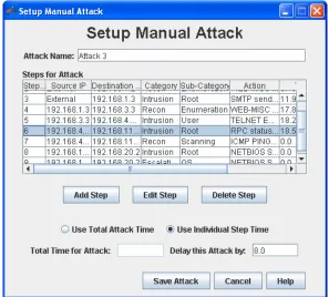
(40) The machines within the simulated network are provided with attributes, such as an IP address, the type of access, and the use of an IDS sensor, to assist in the attack modeling. The IP address is used as a unique identifier, the type of access (internet access) controls whether attacks could start at a machine, and use of an IDS sensor dictates whether the machine would generate appropriate IDS alerts (for the corresponding sensor type) based on the traffic to/from the sensor. Kistner (2006) also expanded upon these attributes to add an indication of the type of machine (whether it was a PC or a server) and the operating system. These attributes are important because they narrow down the type of attack exploits that can be performed on a machine. However, there are still more attributes that should be considered in effectively modeling what exploits can occur, especially with respect to a machine’s software and services. Additionally, the ability to represent a group (or subnet) of machines can simplify the process of modeling networks. The connectors within the simulated network are also provided with the use of an IDS sensor, which functions in the same way as with the machines. In reality, though, there exist differences between these two types of sensors (network-based and host-based sensors) that should be considered in the simulation model. The IDS alerts are generated by matching the attack (or noise) traffic with a sensor alert through a file containing direct correlations between the attack signatures and the alert messages. The Cyber Attack Simulator, through integration with VBA, provides forms for setting up attacks on the modeled networks. Cyber attacks, initially, have to be specified by the user. A source (attacking) machine and a target (attacked) machine are specified for each step, along with what exploit or specific category of exploits is going to be used.. 34.
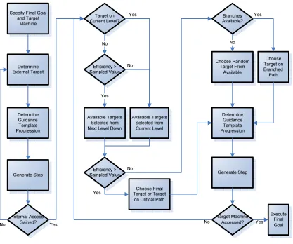
(41) Also, the model is limited to allow only ten attacks and twenty-five steps per attack. This process puts stringent limitations on how much IDS alert data can be generated, and introduces significant user bias to the system.. For these reasons, Kistner (2006). developed an automatic attack methodology that generates a set of attack steps based on several attack parameters provided by the user. These parameters primarily include the target machine, goal type, efficiency of the attack, stealth of the attack, and the average step time. The efficiency relates to the directness of the attack and how successful the steps are, while the stealth relates to how hidden the attack is from being detected by avoiding certain categories of exploits. Although the methodology provided a good basis for developing unbiased attacks in a short amount of time, there are still significant limitations to the types of attacks possible. Considerations regarding the parameters provided and the logic within the methodology can lead to significant improvements in the attack generation process.. 35.
(42) 5 Simulation Model Structure Prior to this thesis, the cyber attack simulator was initially developed using the ARENA software. This development resulted in a model with basic network editing capabilities and a reasonable level of attack specification capabilities. Although this ARENA model has proved that the concept of simulating cyber attacks is plausible, the new features desired for the model, such as working with XML data, are beyond the limitations of ARENA. The desire to overcome such limitations has since motivated the development of an independent simulation model that can be appropriately configured to implement features that are not possible with the ARENA simulator. This new model includes a customized interface specific to the development of network structures and attack scenarios, a series of input and output options, and more detailed features in defining the networks and attack scenarios. The model was developed using the object-oriented programming language Java. Java has many desirable characteristics in modeling realistic environments. Java is also a cross-platform programming language that only requires the JRE (Java runtime environment) to run a java program on any platform. The remainder of this section discusses the primary intentions of the model, provides a background of the development environment used, and presents the structure of the modeling elements. 5.1. Modeling Intentions and Model Overview The overall goal of developing this cyber attack simulation model is to create an. application that can generate valid intrusion detection system alerts in a virtual network representative of a real private network. With the cyber attack simulator, a user can. 36.
(43) create or load a specific network topology, specify the vulnerabilities of the network, create and run attack scenarios, and view sensor alert data produced. Several inputs and outputs are necessary to the functionality of the simulator. A diagram depicting the types of inputs and outputs is displayed in Figure 5.1.. Figure 5.1: Cyber Attack Simulator Functionality As is shown in Figure 5.1, the simulator consists of three primary categories of inputs and outputs: configuration inputs, XML imports and exports, and scenario results. A sensor management add-on, developed by McConky (2007) is also shown. The configuration inputs include data that is loaded from files as the simulator is opened. The guidance template file is a directed graph that indicates what sequence of stages can be used in an attack and what categories of exploits are included in each stage. This information is used when attacks are generated based on a set of parameters. Another file includes the service to vulnerability mappings, which maps a machine service to a set of vulnerabilities through the use of service IDs and vulnerability IDs. 37.
(44) This effectively indicates what exploits can be executed on a machine that is running a certain service. The default exploits file loads a database of known exploits (also referred to as available actions) that the simulator can choose and filter from. This database of actions is used by the simulator when creating the individual steps of an attack as well as when creating the noise (or false-positives) that occurs during an attack scenario. The XML imports and exports allow for structured XML documents to be created by or interpreted by the simulator. These documents can also be created by and interpreted by other applications, providing a means by which the simulator can interface with these applications. A document that is commonly used by the information fusion tools in development is the “Virtual Terrain” XML document. This document depicts the detailed structure of a network, whether the network is real or virtual. Figure 5.2 shows how the virtual terrain document is used among different applications. The cyber attack simulator specifically can read in a network model from the virtual terrain or create a virtual terrain document from a network that has been modeled. Therefore, applications that make use of the alert data generated by the simulator can also be provided with the entire structure of the network used to generate the data. Also, an additional XML document depicting the set of attacks in an attack scenario can be created by or read in by the simulator.. 38.
(45) Figure 5.2: Integration of Virtual Terrain The scenario results include data that is generated during an attack scenario run and output into text files. A ground truth file lists all of the attack-based actions that occur, along with details such as the attack that the action belonged to, the source and destination of the attack, and the success or failure of the action. A set of sensor alert files list all of the IDS alerts generated by sensors placed in the network model, with a separate file for each sensor. These IDS alerts correspond to both attack-based actions and noise-based actions. Lastly, the sensor management add-on includes the appropriate functionality to define rules for the manner in which sensors handle the alerts generated. A fusion engine queue is modeled, and alerts are sent to this queue as defined by the sensor rules. Performance metrics are generated for purposes of comparing the sensor rules. For more information regarding the sensor management add-on and the underlying methodology, refer to McConky (2007).. 39.
(46) 5.2. Java Background Before delving into the details of the program’s structure, the reader needs to have a. basic understanding of Java’s object-oriented approach. This section describes some of the basic features and benefits of the Java programming language. Those familiar with the basic structure of Java (or a similar object-oriented language) can proceed to the next section. The Java language is implemented as an object-oriented programming language. The primary approach in object-oriented programming is to represent real-world objects, such as people or machines, as programming classes with unique attributes and functions (or methods) that the objects can provide. Simulations in general attempt to provide an accurate model of some real-world situation that can be manipulated and studied to evaluate existing or proposed systems.. Therefore, the use of object-oriented. programming in developing a simulation framework has many benefits when considering that simulation models tend to represent the interactions between real objects (Bischack and Roberts, 1991). For example, in the case of the cyber attack simulator, a Sensor class is used to represent a real-world IDS sensor. Each sensor included in a modeled network represents one instance of this class. A sensor instance is then given unique attributes, which include the location, type, alerts produced, etc. The class also includes methods that each instance can use, such as adding a new alert to the sensor’s list of alerts or outputting all of the alerts produced to a text file. In addition to the use of classes in representing objects, Java has other key features that help in providing the modularity and reusability to make a simple and flexible. 40.
Figure


+7
Related documents
The results showed that bulk density and soil strength at upper layer after 24 years of cropping were similar among treatments, but the soil strength under IT at 50-60 cm depth
ryn March’s study on the Solu Khumbu Sherpa almost 40 years ago (1977), community mountain-closure rituals and practices appear to have been defunct at the time of docu-
Brown and Warner, Measuring security price performance , 205.. sooner and faster to bad than to good news. Third, the statistical analysis for market efficiency suggests that the
In the United Kingdom, one particularly effective plastic card fraud prevention strategy involved a high profile publicity and education campaign by the Association for Payment
An explanatory paragraph following the opinion paragraph, describing that (i) the statement of social insurance presents the actuarial present value of the agency’s estimated
In addition, when you are building your business based on automated field workers, the downtime from damaged devices or loss of data can quickly have a bigger impact than the cost
We will show that the simple polarized incoherent phase observed in Ref.(25) can be captured by perturbation theory and show that its excited states can be reproduced by
Foreign-Trade Zone No. 79 received its Grant of Authority from the U.S. Foreign-Trade Zones Board in 1982. The City of Tampa is the Grantee. In 1989 the City of Tampa sponsored
